torque CHEVROLET DYNASTY 1993 User Guide
[x] Cancel search | Manufacturer: CHEVROLET, Model Year: 1993, Model line: DYNASTY, Model: CHEVROLET DYNASTY 1993Pages: 2438, PDF Size: 74.98 MB
Page 73 of 2438
made by using a (M10 x 1.5 - 6H) thread chasing tap
on the holes to restore the threads to a usable condi-
tion. If threads can be restored to a usable condition,
install sway bar retainer attaching bolts and torque
to 68 N Im (50 ft. lbs.).
CAUTION: When performing repair procedure listed
below. Be sure replacement bolts and nuts meet the
same requirements as the original equipment man-
ufactures specifications.
If damage to threaded holes in lower control arm,
can not be restored to a usable condition using the
above procedure. Drill out holes in lower control arm
using an 11 mm drill bit. Then use a bolt and nut for
attachment of sway bar retainer to lower control
arm. Torque the nut and bolt to 68 N Im (50 ft. lbs.).
REMOVAL
(1) Raise and support the vehicle. See Hoisting in
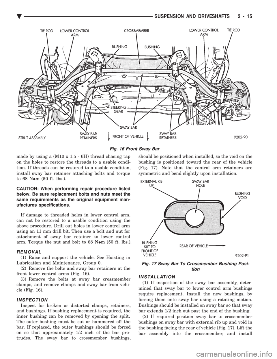
Lubrication and Maintenance, Group 0. (2) Remove the bolts and sway bar retainers at the
front lower control arms (Fig. 16). (3) Remove the bolts at sway bar crossmember
clamps, and remove clamps and sway bar from vehi-
cle (Fig. 16).
INSPECTION
Inspect for broken or distorted clamps, retainers,
and bushings. If bushing replacement is required, the
inner bushing can be removed by opening the split.
The outer bushing must be cut or hammered off the
bar. If replaced, the outer bushings should be forced
on so that approximately 1/2 inch of the bar pro-
trudes. The sway bar to crossmember bushings, should be positioned when installed, so the void on the
bushing is positioned toward the rear of the vehicle
(Fig. 17). Note that the control arm retainers are
symmetric and bend slightly upon installation.
INSTALLATION
(1) If inspection of the sway bar assembly, deter-
mined that sway bar to lower control arm bushings
require replacement. Install the new bushings, by
forcing them onto sway bar using a rotating motion.
Bushings should be installed on sway bar so that sway
bar extends 1/2 inch out past the end of the bushing. (2) If required position sway bar to crossmember
bushings on sway bar with external rib up and void in
the bushing facing the rear of vehicle (Fig. 17). Lift the
bar assembly into the crossmember, and install
Fig. 16 Front Sway Bar
Fig. 17 Sway Bar To Crossmember Bushing Posi- tion
Ä SUSPENSION AND DRIVESHAFTS 2 - 15
Page 74 of 2438
the lower clamps and bolts. The center offset in the
sway bar should be oriented toward the front of the
vehicle (Fig. 16)(3) Position bushing retainers on lower control arms
and install bolts (Fig. 16). (4) With lower control arms raised to design height,
tighten all retainer attaching bolts to 70 N Im (50 ft.
lbs.) torque. (5) Lower vehicle.
KNUCKLE (FRONT SUSPENSION)
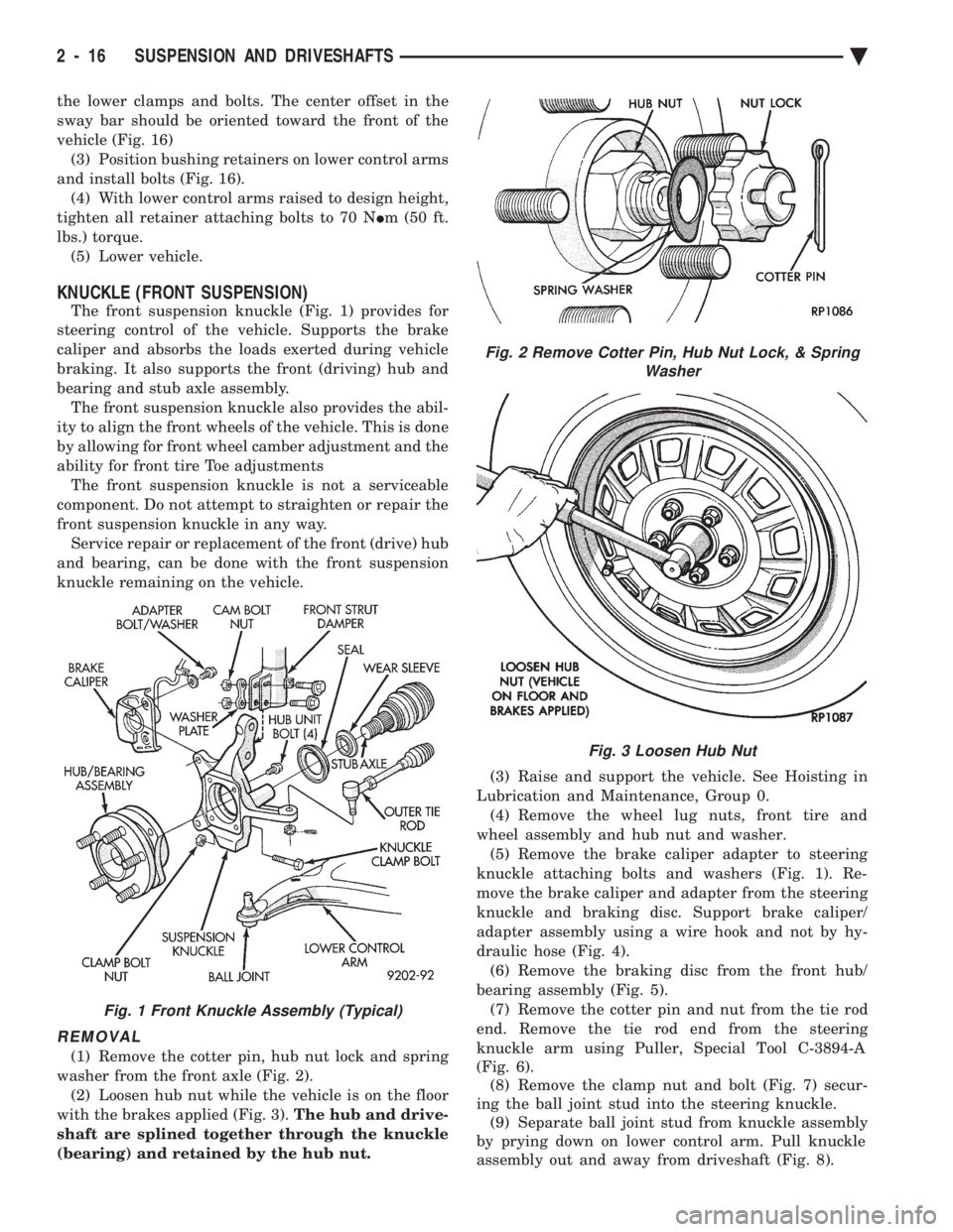
The front suspension knuckle (Fig. 1) provides for
steering control of the vehicle. Supports the brake
caliper and absorbs the loads exerted during vehicle
braking. It also supports the front (driving) hub and
bearing and stub axle assembly. The front suspension knuckle also provides the abil-
ity to align the front wheels of the vehicle. This is done
by allowing for front wheel camber adjustment and the
ability for front tire Toe adjustments The front suspension knuckle is not a serviceable
component. Do not attempt to straighten or repair the
front suspension knuckle in any way. Service repair or replacement of the front (drive) hub
and bearing, can be done with the front suspension
knuckle remaining on the vehicle.
REMOVAL
(1) Remove the cotter pin, hub nut lock and spring
washer from the front axle (Fig. 2). (2) Loosen hub nut while the vehicle is on the floor
with the brakes applied (Fig. 3). The hub and drive-
shaft are splined together through the knuckle
(bearing) and retained by the hub nut. (3) Raise and support the vehicle. See Hoisting in
Lubrication and Maintenance, Group 0. (4) Remove the wheel lug nuts, front tire and
wheel assembly and hub nut and washer. (5) Remove the brake caliper adapter to steering
knuckle attaching bolts and washers (Fig. 1). Re-
move the brake caliper and adapter from the steering
knuckle and braking disc. Support brake caliper/
adapter assembly using a wire hook and not by hy-
draulic hose (Fig. 4). (6) Remove the braking disc from the front hub/
bearing assembly (Fig. 5). (7) Remove the cotter pin and nut from the tie rod
end. Remove the tie rod end from the steering
knuckle arm using Puller, Special Tool C-3894-A
(Fig. 6). (8) Remove the clamp nut and bolt (Fig. 7) secur-
ing the ball joint stud into the steering knuckle. (9) Separate ball joint stud from knuckle assembly
by prying down on lower control arm. Pull knuckle
assembly out and away from driveshaft (Fig. 8).
Fig. 2 Remove Cotter Pin, Hub Nut Lock, & Spring Washer
Fig. 3 Loosen Hub Nut
Fig. 1 Front Knuckle Assembly (Typical)
2 - 16 SUSPENSION AND DRIVESHAFTS Ä
Page 76 of 2438
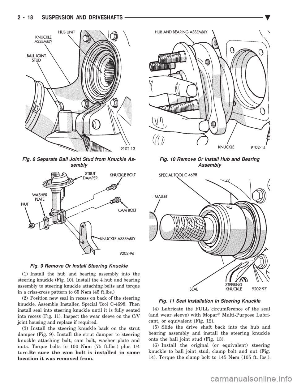
(1) Install the hub and bearing assembly into the
steering knuckle (Fig. 10). Install the 4 hub and bearing
assembly to steering knuckle attaching bolts and torque
in a criss-cross pattern to 65 N Im (45 ft.lbs.)
(2) Position new seal in recess on back of the steering
knuckle. Assemble Installer, Special Tool C-4698. Then
install seal into steering knuckle until it is fully seated
into recess (Fig. 11). Inspect the wear sleeve on the C/V
joint housing and replace if required.
(3) Install the steering knuckle back on the strut
damper (Fig. 9). Install the strut damper to steering
knuckle attaching bolt, cam bolt, washer plate and
nuts. Torque bolts to 100 N Im (75 ft.lbs.) plus 1/4
turn. Be sure the cam bolt is installed in same
location it was removed from. (4) Lubricate the FULL circumference of the seal
(and wear sleeve) with Mopar tMulti-Purpose Lubri-
cant, or equivalent (Fig. 12). (5) Slide the drive shaft back into the hub and
bearing assembly and install the steering knuckle
onto the ball joint stud (Fig. 13). (6) Install the original (or equivalent) steering
knuckle to ball joint stud, clamp bolt and nut (Fig.
14). Torque the clamp bolt to 145 N Im (105 ft. lbs.).
Fig. 10 Remove Or Install Hub and Bearing
Assembly
Fig. 11 Seal Installation In Steering Knuckle
Fig. 8 Separate Ball Joint Stud from Knuckle As- sembly
Fig. 9 Remove Or Install Steering Knuckle
2 - 18 SUSPENSION AND DRIVESHAFTS Ä
Page 77 of 2438
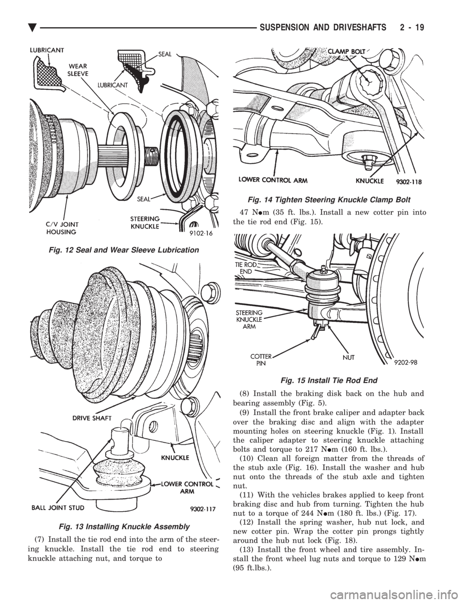
(7) Install the tie rod end into the arm of the steer-
ing knuckle. Install the tie rod end to steering
knuckle attaching nut, and torque to 47 N
Im (35 ft. lbs.). Install a new cotter pin into
the tie rod end (Fig. 15).
(8) Install the braking disk back on the hub and
bearing assembly (Fig. 5). (9) Install the front brake caliper and adapter back
over the braking disc and align with the adapter
mounting holes on steering knuckle (Fig. 1). Install
the caliper adapter to steering knuckle attaching
bolts and torque to 217 N Im (160 ft. lbs.).
(10) Clean all foreign matter from the threads of
the stub axle (Fig. 16). Install the washer and hub
nut onto the threads of the stub axle and tighten
nut. (11) With the vehicles brakes applied to keep front
braking disc and hub from turning. Tighten the hub
nut to a torque of 244 N Im (180 ft. lbs.) (Fig. 17).
(12) Install the spring washer, hub nut lock, and
new cotter pin. Wrap the cotter pin prongs tightly
around the hub nut lock (Fig. 18). (13) Install the front wheel and tire assembly. In-
stall the front wheel lug nuts and torque to 129 N Im
(95 ft.lbs.).
Fig. 13 Installing Knuckle Assembly
Fig. 12 Seal and Wear Sleeve Lubrication
Fig. 14 Tighten Steering Knuckle Clamp Bolt
Fig. 15 Install Tie Rod End
Ä SUSPENSION AND DRIVESHAFTS 2 - 19
Page 79 of 2438
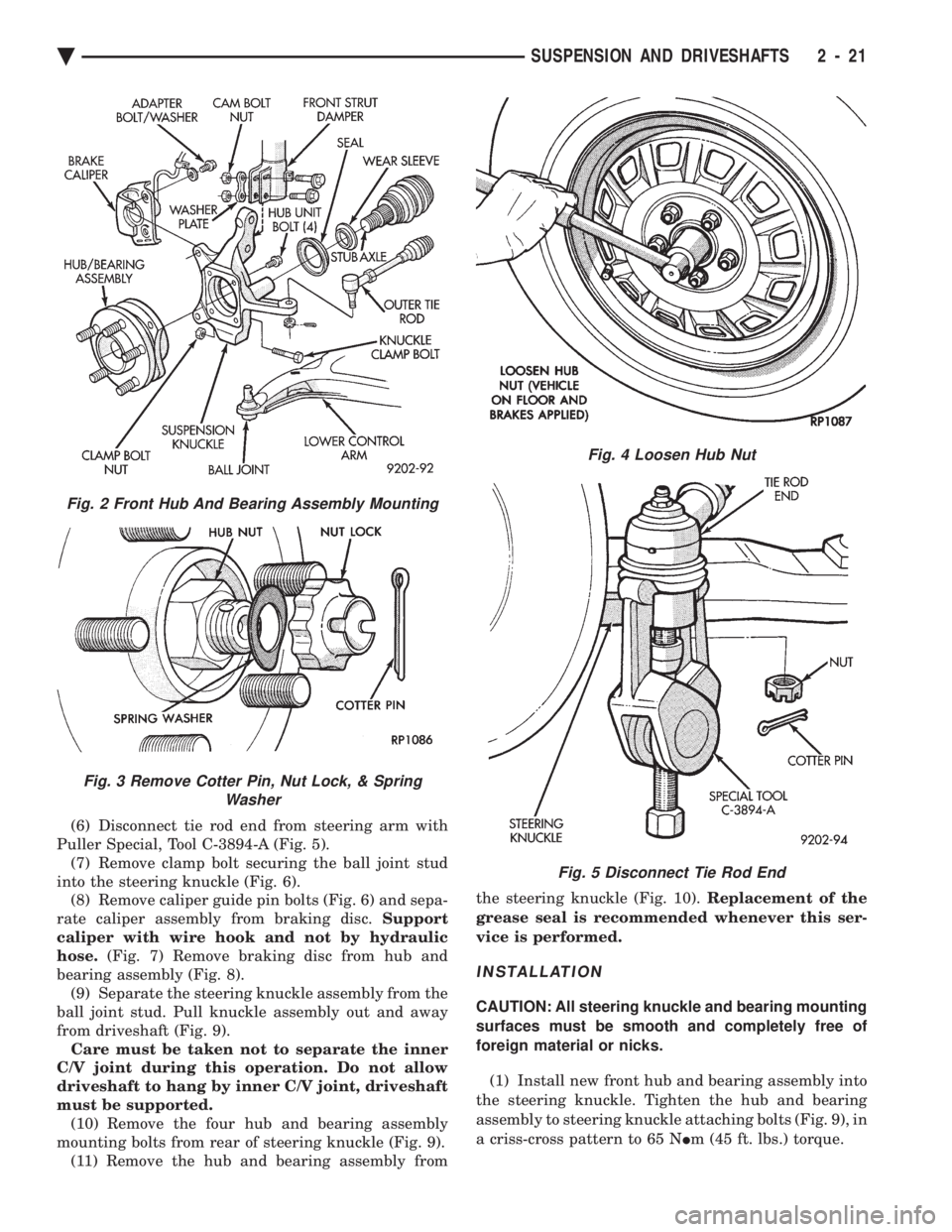
(6) Disconnect tie rod end from steering arm with
Puller Special, Tool C-3894-A (Fig. 5). (7) Remove clamp bolt securing the ball joint stud
into the steering knuckle (Fig. 6). (8) Remove caliper guide pin bolts (Fig. 6) and sepa-
rate caliper assembly from braking disc. Support
caliper with wire hook and not by hydraulic
hose. (Fig. 7) Remove braking disc from hub and
bearing assembly (Fig. 8). (9) Separate the steering knuckle assembly from the
ball joint stud. Pull knuckle assembly out and away
from driveshaft (Fig. 9). Care must be taken not to separate the inner
C/V joint during this operation. Do not allow
driveshaft to hang by inner C/V joint, driveshaft
must be supported. (10) Remove the four hub and bearing assembly
mounting bolts from rear of steering knuckle (Fig. 9). (11) Remove the hub and bearing assembly from the steering knuckle (Fig. 10).
Replacement of the
grease seal is recommended whenever this ser-
vice is performed.
INSTALLATION
CAUTION: All steering knuckle and bearing mounting
surfaces must be smooth and completely free of
foreign material or nicks.
(1) Install new front hub and bearing assembly into
the steering knuckle. Tighten the hub and bearing
assembly to steering knuckle attaching bolts (Fig. 9), in
a criss-cross pattern to 65 N Im (45 ft. lbs.) torque.
Fig. 2 Front Hub And Bearing Assembly Mounting
Fig. 3 Remove Cotter Pin, Nut Lock, & Spring
Washer
Fig. 4 Loosen Hub Nut
Fig. 5 Disconnect Tie Rod End
Ä SUSPENSION AND DRIVESHAFTS 2 - 21
Page 81 of 2438
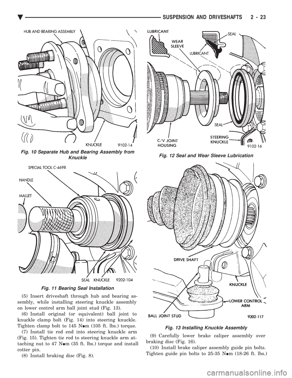
(5) Insert driveshaft through hub and bearing as-
sembly, while installing steering knuckle assembly
on lower control arm ball joint stud (Fig. 13). (6) Install original (or equivalent) ball joint to
knuckle clamp bolt (Fig. 14) into steering knuckle.
Tighten clamp bolt to 145 N Im (105 ft. lbs.) torque.
(7) Install tie rod end into steering knuckle arm
(Fig. 15). Tighten tie rod to steering knuckle arm at-
taching nut to 47 N Im (35 ft. lbs.) torque and install
cotter pin. (8) Install braking disc (Fig. 8). (9) Carefully lower brake caliper assembly over
braking disc (Fig. 16). (10) Install brake caliper assembly guide pin bolts.
Tighten guide pin bolts to 25-35 N Im (18-26 ft. lbs.)
Fig. 10 Separate Hub and Bearing Assembly from
Knuckle
Fig. 11 Bearing Seal Installation
Fig. 12 Seal and Wear Sleeve Lubrication
Fig. 13 Installing Knuckle Assembly
Ä SUSPENSION AND DRIVESHAFTS 2 - 23
Page 82 of 2438
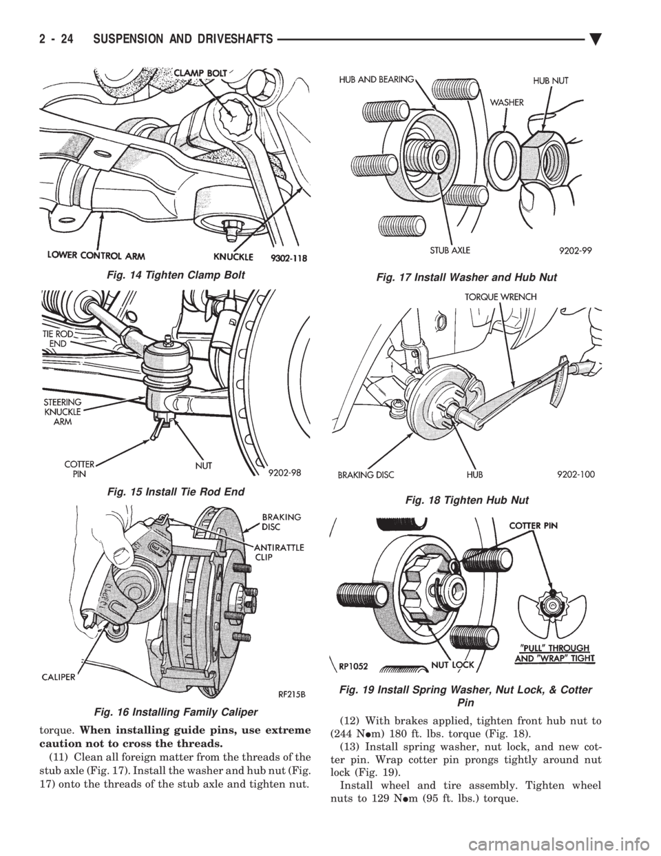
torque. When installing guide pins, use extreme
caution not to cross the threads. (11) Clean all foreign matter from the threads of the
stub axle (Fig. 17). Install the washer and hub nut (Fig.
17) onto the threads of the stub axle and tighten nut. (12) With brakes applied, tighten front hub nut to
(244 N Im) 180 ft. lbs. torque (Fig. 18).
(13) Install spring washer, nut lock, and new cot-
ter pin. Wrap cotter pin prongs tightly around nut
lock (Fig. 19). Install wheel and tire assembly. Tighten wheel
nuts to 129 N Im (95 ft. lbs.) torque.
Fig. 15 Install Tie Rod End
Fig. 16 Installing Family Caliper
Fig. 17 Install Washer and Hub Nut
Fig. 18 Tighten Hub Nut
Fig. 19 Install Spring Washer, Nut Lock, & Cotter
Pin
Fig. 14 Tighten Clamp Bolt
2 - 24 SUSPENSION AND DRIVESHAFTS Ä
Page 87 of 2438
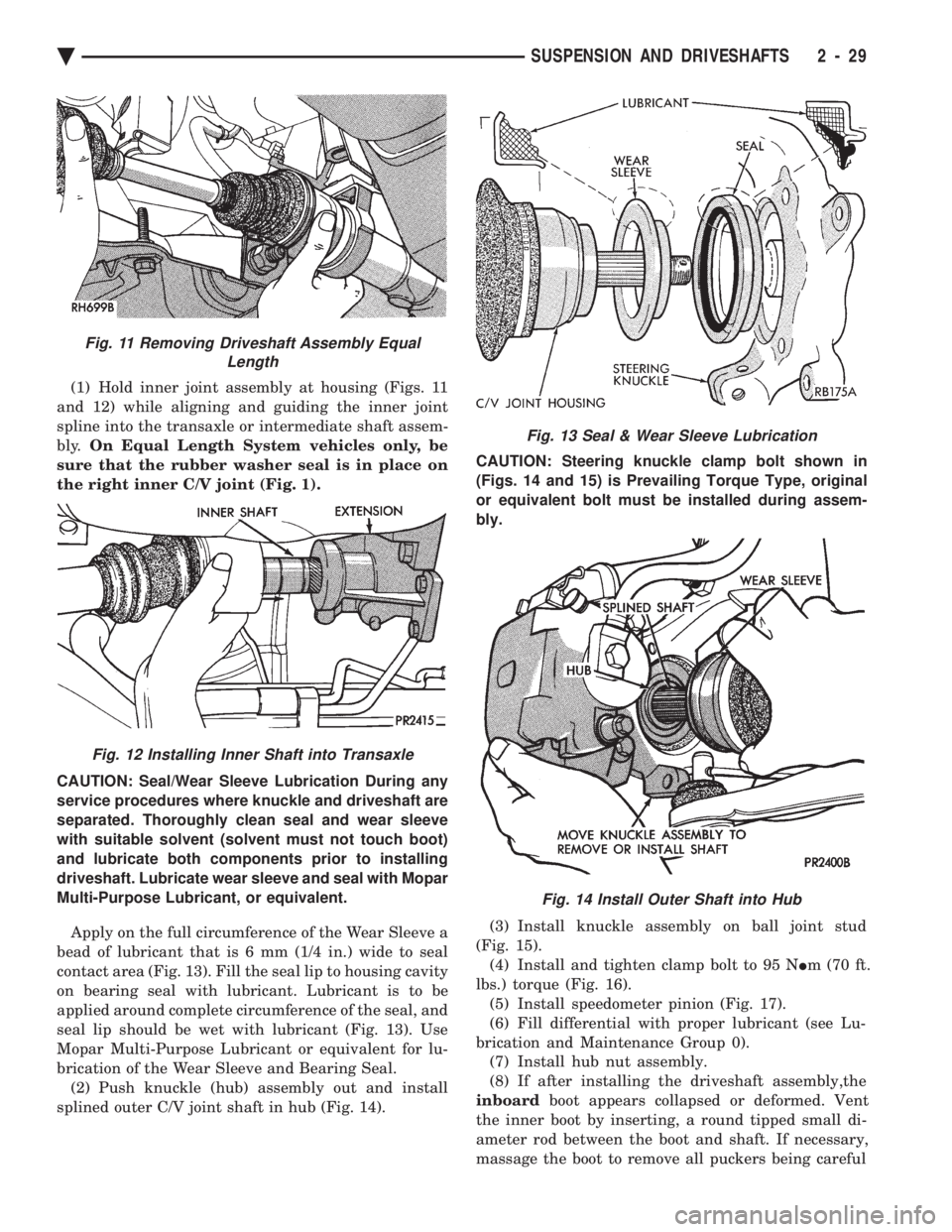
(1) Hold inner joint assembly at housing (Figs. 11
and 12) while aligning and guiding the inner joint
spline into the transaxle or intermediate shaft assem-
bly. On Equal Length System vehicles only, be
sure that the rubber washer seal is in place on
the right inner C/V joint (Fig. 1).
CAUTION: Seal/Wear Sleeve Lubrication During any
service procedures where knuckle and driveshaft are
separated. Thoroughly clean seal and wear sleeve
with suitable solvent (solvent must not touch boot)
and lubricate both components prior to installing
driveshaft. Lubricate wear sleeve and seal with Mopar
Multi-Purpose Lubricant, or equivalent.
Apply on the full circumference of the Wear Sleeve a
bead of lubricant that is 6 mm (1/4 in.) wide to seal
contact area (Fig. 13). Fill the seal lip to housing cavity
on bearing seal with lubricant. Lubricant is to be
applied around complete circumference of the seal, and
seal lip should be wet with lubricant (Fig. 13). Use
Mopar Multi-Purpose Lubricant or equivalent for lu-
brication of the Wear Sleeve and Bearing Seal. (2) Push knuckle (hub) assembly out and install
splined outer C/V joint shaft in hub (Fig. 14). CAUTION: Steering knuckle clamp bolt shown in
(Figs. 14 and 15) is Prevailing Torque Type, original
or equivalent bolt must be installed during assem-
bly.
(3) Install knuckle assembly on ball joint stud
(Fig. 15). (4) Install and tighten clamp bolt to 95 N Im (70 ft.
lbs.) torque (Fig. 16). (5) Install speedometer pinion (Fig. 17).
(6) Fill differential with proper lubricant (see Lu-
brication and Maintenance Group 0). (7) Install hub nut assembly.
(8) If after installing the driveshaft assembly,the
inboard boot appears collapsed or deformed. Vent
the inner boot by inserting, a round tipped small di-
ameter rod between the boot and shaft. If necessary,
massage the boot to remove all puckers being careful
Fig. 13 Seal & Wear Sleeve Lubrication
Fig. 14 Install Outer Shaft into Hub
Fig. 11 Removing Driveshaft Assembly Equal Length
Fig. 12 Installing Inner Shaft into Transaxle
Ä SUSPENSION AND DRIVESHAFTS 2 - 29
Page 88 of 2438
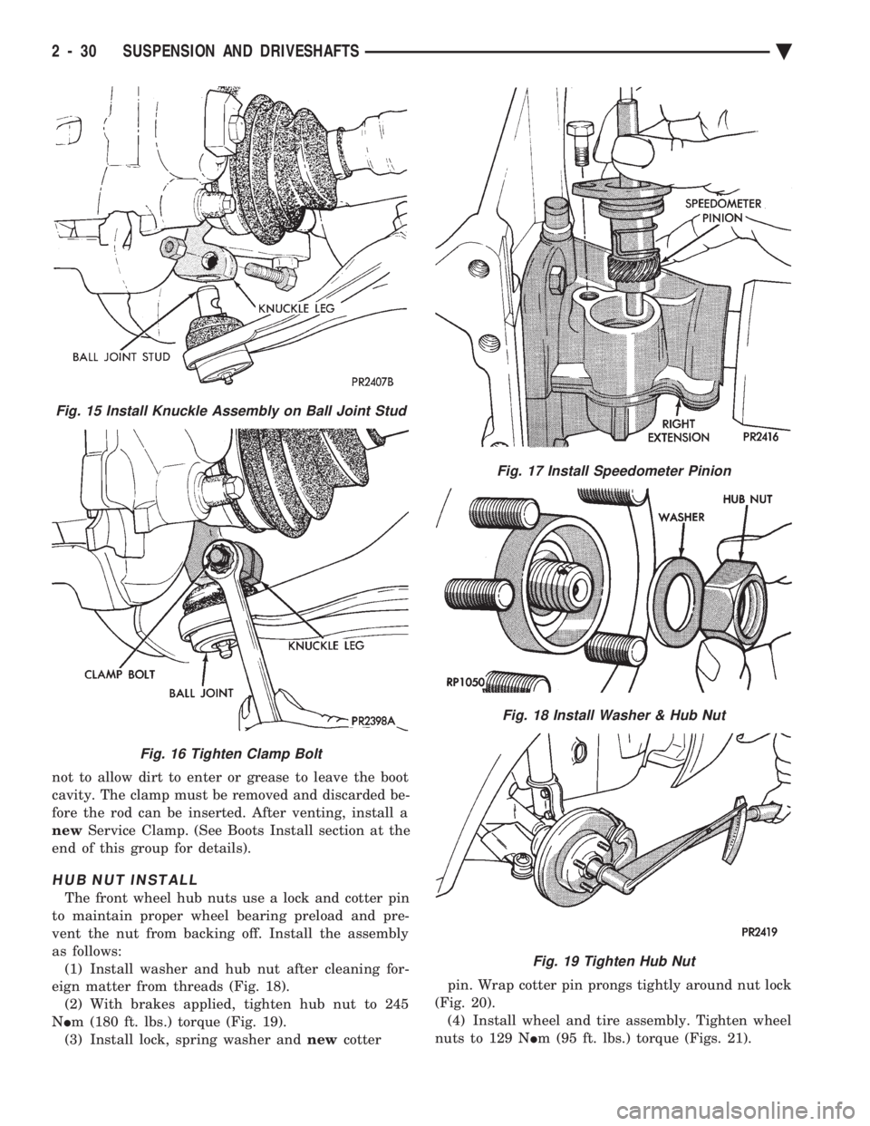
not to allow dirt to enter or grease to leave the boot
cavity. The clamp must be removed and discarded be-
fore the rod can be inserted. After venting, install a
new Service Clamp. (See Boots Install section at the
end of this group for details).
HUB NUT INSTALL
The front wheel hub nuts use a lock and cotter pin
to maintain proper wheel bearing preload and pre-
vent the nut from backing off. Install the assembly
as follows: (1) Install washer and hub nut after cleaning for-
eign matter from threads (Fig. 18). (2) With brakes applied, tighten hub nut to 245
N Im (180 ft. lbs.) torque (Fig. 19).
(3) Install lock, spring washer and newcotter pin. Wrap cotter pin prongs tightly around nut lock
(Fig. 20). (4) Install wheel and tire assembly. Tighten wheel
nuts to 129 N Im (95 ft. lbs.) torque (Figs. 21).
Fig. 15 Install Knuckle Assembly on Ball Joint Stud
Fig. 16 Tighten Clamp Bolt
Fig. 17 Install Speedometer Pinion
Fig. 18 Install Washer & Hub Nut
Fig. 19 Tighten Hub Nut
2 - 30 SUSPENSION AND DRIVESHAFTS Ä
Page 101 of 2438
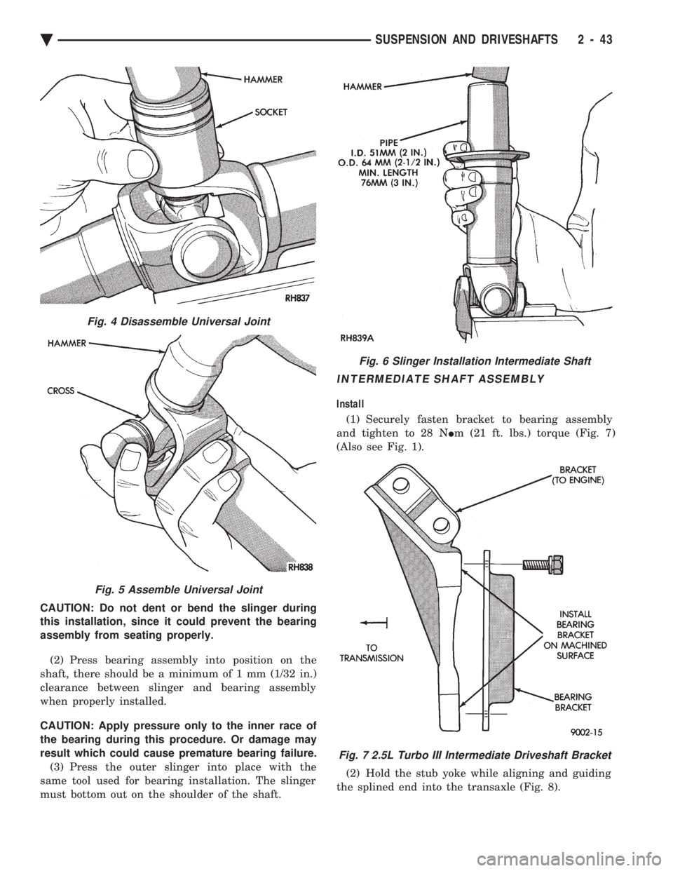
CAUTION: Do not dent or bend the slinger during
this installation, since it could prevent the bearing
assembly from seating properly. (2) Press bearing assembly into position on the
shaft, there should be a minimum of 1 mm (1/32 in.)
clearance between slinger and bearing assembly
when properly installed.
CAUTION: Apply pressure only to the inner race of
the bearing during this procedure. Or damage may
result which could cause premature bearing failure. (3) Press the outer slinger into place with the
same tool used for bearing installation. The slinger
must bottom out on the shoulder of the shaft.
INTERMEDIATE SHAFT ASSEMBLY
Install
(1) Securely fasten bracket to bearing assembly
and tighten to 28 N Im (21 ft. lbs.) torque (Fig. 7)
(Also see Fig. 1).
(2) Hold the stub yoke while aligning and guiding
the splined end into the transaxle (Fig. 8).
Fig. 4 Disassemble Universal Joint
Fig. 5 Assemble Universal Joint
Fig. 6 Slinger Installation Intermediate Shaft
Fig. 7 2.5L Turbo III Intermediate Driveshaft Bracket
Ä SUSPENSION AND DRIVESHAFTS 2 - 43