wiring CHEVROLET DYNASTY 1993 Owner's Manual
[x] Cancel search | Manufacturer: CHEVROLET, Model Year: 1993, Model line: DYNASTY, Model: CHEVROLET DYNASTY 1993Pages: 2438, PDF Size: 74.98 MB
Page 137 of 2438
(2) Check all connectors for correct assembly. Check
all connectors for incorrectly installed termi-
nals. (3) Check pin #21 for minimum of 9.5 volts.
(4) Check pin #20 for minimum of 9.5 volts (with
ignition key on). (5) Check voltage at pins #5 and #16. The measure-
ment should exceed 0 volts. (6) Check pin #19 for continuity.
(7) The engine speed should exceed 680 rpm during
idle. All doors and trunk must be closed for the
system to function.
DIAGNOSTICS PROCEDURES
(1) Use the D.R.B. II tester and the 1991 air suspen-
sion diagnostic service cartridge to begin the trouble-
shooting process. (2) Use the D.R.B. mating connector under the dash
(drivers side) to plug-in the D.R.B. II test connector
(Fig. 10). (3) The tester will conduct a complete check of the
suspension system status. (4) The tester will list the steps to follow to access
and diagnose the failure. (5) A Volt/Ohm meter can be used for some diagnos-
tic testing.
HEIGHT SENSOR CHECK
If a sensor signal/signals are missing. Follow the
repair procedure listed below. (1) Check ground circuit continuity. (Remember
front and rear grounds are on different circuits. (2) For front ground circuit continuity check circuit
S 33. (3) For rear ground circuit continuity check circuit
X20. (4) Refer to control module pin out chart and wiring
diagram (see Group 8F in wiring diagram manual) for
individual circuit details. (5) If open circuits are not found replace the compo-
nent. Complete circuit testing and connector assem-
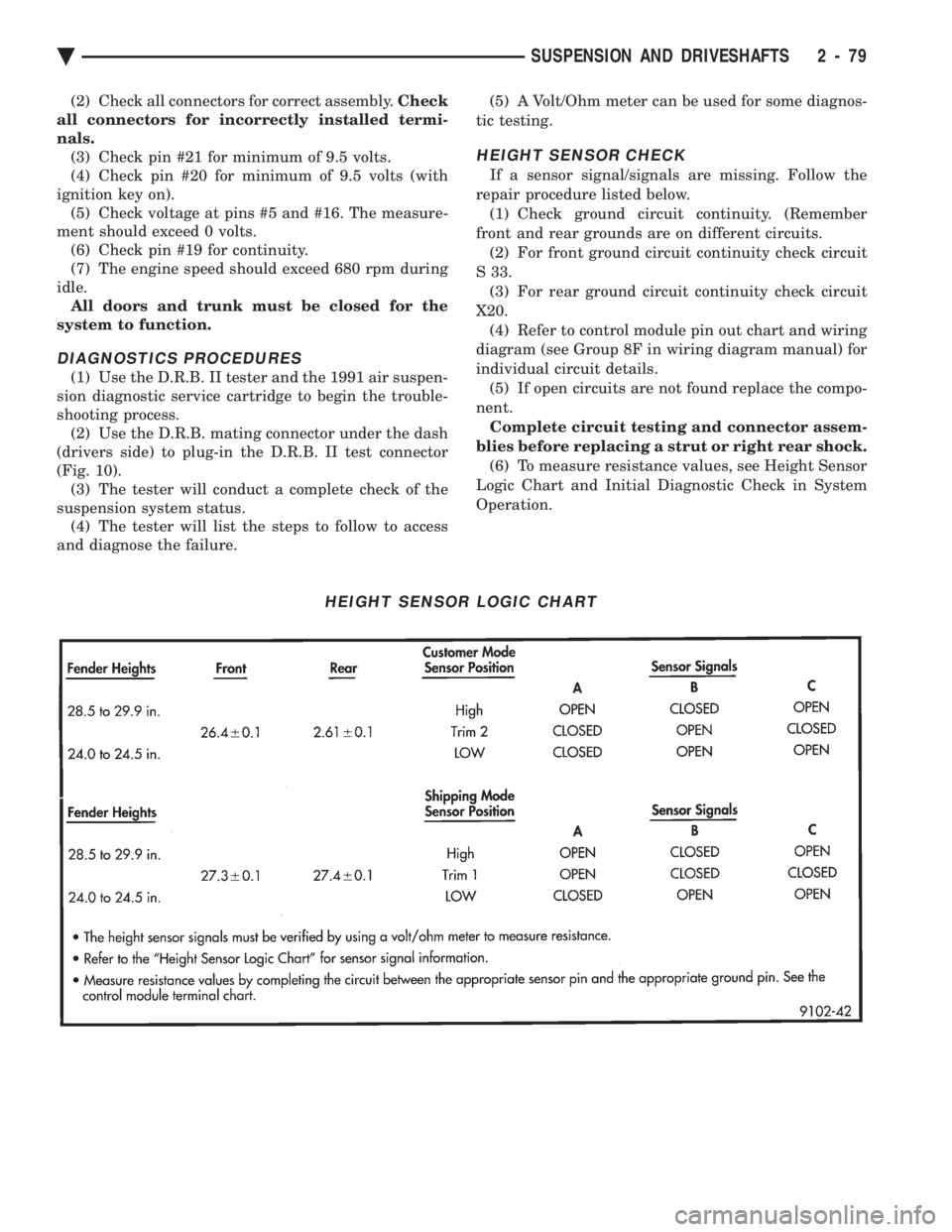
blies before replacing a strut or right rear shock. (6) To measure resistance values, see Height Sensor
Logic Chart and Initial Diagnostic Check in System
Operation.
HEIGHT SENSOR LOGIC CHART
Ä SUSPENSION AND DRIVESHAFTS 2 - 79
Page 143 of 2438
SERVICE PROCEDURES
CONTROL MODULE (ASCM)
REMOVAL (1) Disconnect negative battery cable.
(2) Remove right side trunk trim panel.
(3) Remove electrical connectors from control mod-
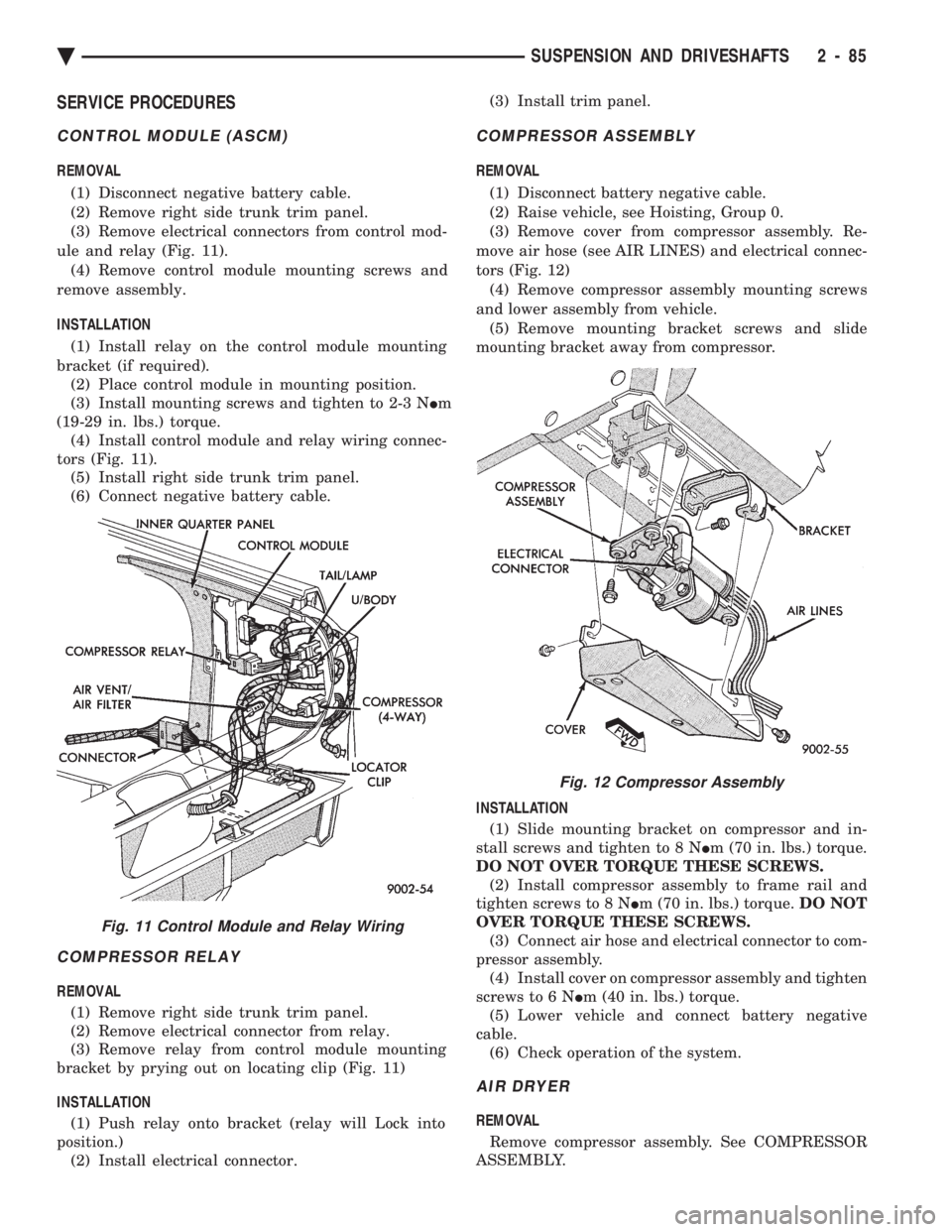
ule and relay (Fig. 11). (4) Remove control module mounting screws and
remove assembly.
INSTALLATION
(1) Install relay on the control module mounting
bracket (if required). (2) Place control module in mounting position.
(3) Install mounting screws and tighten to 2-3 N Im
(19-29 in. lbs.) torque. (4) Install control module and relay wiring connec-
tors (Fig. 11). (5) Install right side trunk trim panel.
(6) Connect negative battery cable.
COMPRESSOR RELAY
REMOVAL
(1) Remove right side trunk trim panel.
(2) Remove electrical connector from relay.
(3) Remove relay from control module mounting
bracket by prying out on locating clip (Fig. 11)
INSTALLATION (1) Push relay onto bracket (relay will Lock into
position.) (2) Install electrical connector. (3) Install trim panel.
COMPRESSOR ASSEMBLY
REMOVAL
(1) Disconnect battery negative cable.
(2) Raise vehicle, see Hoisting, Group 0.
(3) Remove cover from compressor assembly. Re-
move air hose (see AIR LINES) and electrical connec-
tors (Fig. 12) (4) Remove compressor assembly mounting screws
and lower assembly from vehicle. (5) Remove mounting bracket screws and slide
mounting bracket away from compressor.
INSTALLATION (1) Slide mounting bracket on compressor and in-
stall screws and tighten to 8 N Im (70 in. lbs.) torque.
DO NOT OVER TORQUE THESE SCREWS. (2) Install compressor assembly to frame rail and
tighten screws to 8 N Im (70 in. lbs.) torque. DO NOT
OVER TORQUE THESE SCREWS. (3) Connect air hose and electrical connector to com-
pressor assembly. (4) Install cover on compressor assembly and tighten
screws to 6 N Im (40 in. lbs.) torque.
(5) Lower vehicle and connect battery negative
cable. (6) Check operation of the system.
AIR DRYER
REMOVAL
Remove compressor assembly. See COMPRESSOR
ASSEMBLY.
Fig. 11 Control Module and Relay Wiring
Fig. 12 Compressor Assembly
Ä SUSPENSION AND DRIVESHAFTS 2 - 85
Page 145 of 2438
INSTALL
(1) Inspect O-Ring condition and position on sole-
noid stem. (O-Ring can become dislodged during re-
moval (Fig. 16). (2) Install solenoid with tangs to top ledge of hous-
ing and install retaining clip. (3) Reconnect air line and electrical connection.
STRUT (AIR SUSPENSION) DAMPERASSEMBLY
Service procedures for removal and installation for
(air or steel spring) assemblies are essentially the
same. Except for air venting/recharging and discon-
necting/connecting air lines and electrical connection.
REMOVAL (1) Disconnect battery negative cable.
(2) Hoist vehicle and remove wheel and tire assem-
bly. (3) See AIR LINES AND FITTINGS and discon-
nect air line. (4) Disconnect electrical leads, solenoid and height
sensors. (5) See SOLENOIDS (STRUT AND AIR SPRING)
and vent air spring and remove solenoids. (6) See STRUT DAMPER ASSEMBLY in FRONT
SUSPENSION and remove strut.
DISASSEMBLY/ASSEMBLE Disassembly is restricted to upper mount and bear-
ing housing. The strut shock absorber, air spring
with integral height sensor, solenoid and wiring har-
ness are serviced as an assembly. (1) Hold retaining plate locking washer and re-
move strut rod nut. (2) Remove locking washer, retainer plate, spacer,
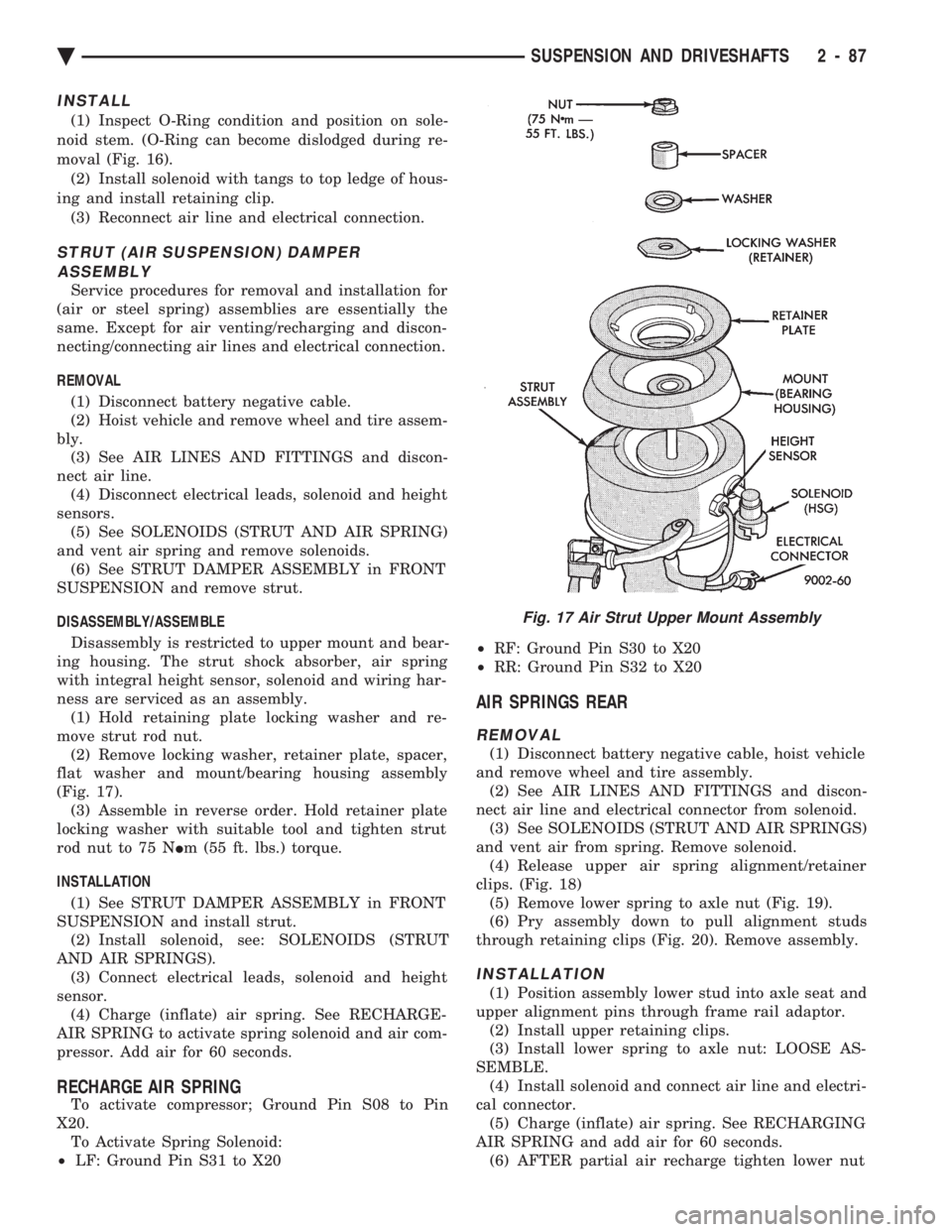
flat washer and mount/bearing housing assembly
(Fig. 17). (3) Assemble in reverse order. Hold retainer plate
locking washer with suitable tool and tighten strut
rod nut to 75 N Im (55 ft. lbs.) torque.
INSTALLATION (1) See STRUT DAMPER ASSEMBLY in FRONT
SUSPENSION and install strut. (2) Install solenoid, see: SOLENOIDS (STRUT
AND AIR SPRINGS). (3) Connect electrical leads, solenoid and height
sensor. (4) Charge (inflate) air spring. See RECHARGE-
AIR SPRING to activate spring solenoid and air com-
pressor. Add air for 60 seconds.
RECHARGE AIR SPRING
To activate compressor; Ground Pin S08 to Pin
X20. To Activate Spring Solenoid:
² LF: Ground Pin S31 to X20 ²
RF: Ground Pin S30 to X20
² RR: Ground Pin S32 to X20
AIR SPRINGS REAR
REMOVAL
(1) Disconnect battery negative cable, hoist vehicle
and remove wheel and tire assembly. (2) See AIR LINES AND FITTINGS and discon-
nect air line and electrical connector from solenoid. (3) See SOLENOIDS (STRUT AND AIR SPRINGS)
and vent air from spring. Remove solenoid. (4) Release upper air spring alignment/retainer
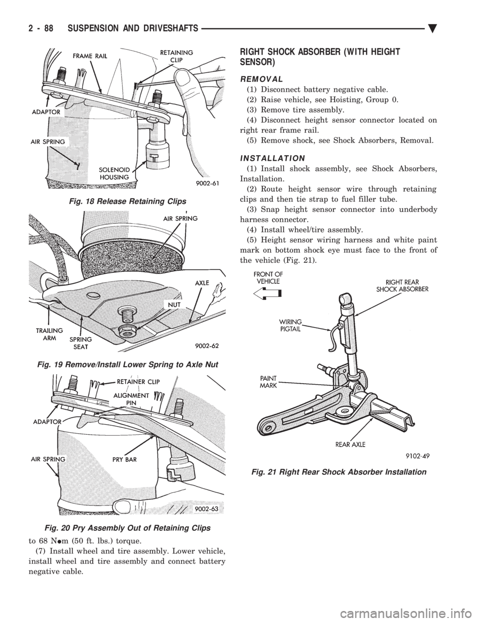
clips. (Fig. 18) (5) Remove lower spring to axle nut (Fig. 19).
(6) Pry assembly down to pull alignment studs
through retaining clips (Fig. 20). Remove assembly.
INSTALLATION
(1) Position assembly lower stud into axle seat and
upper alignment pins through frame rail adaptor. (2) Install upper retaining clips.
(3) Install lower spring to axle nut: LOOSE AS-
SEMBLE. (4) Install solenoid and connect air line and electri-
cal connector. (5) Charge (inflate) air spring. See RECHARGING
AIR SPRING and add air for 60 seconds. (6) AFTER partial air recharge tighten lower nut
Fig. 17 Air Strut Upper Mount Assembly
Ä SUSPENSION AND DRIVESHAFTS 2 - 87
Page 146 of 2438
to 68 N Im (50 ft. lbs.) torque.
(7) Install wheel and tire assembly. Lower vehicle,
install wheel and tire assembly and connect battery
negative cable.
RIGHT SHOCK ABSORBER (WITH HEIGHT
SENSOR)
REMOVAL
(1) Disconnect battery negative cable.
(2) Raise vehicle, see Hoisting, Group 0.
(3) Remove tire assembly.
(4) Disconnect height sensor connector located on
right rear frame rail. (5) Remove shock, see Shock Absorbers, Removal.
INSTALLATION
(1) Install shock assembly, see Shock Absorbers,
Installation. (2) Route height sensor wire through retaining
clips and then tie strap to fuel filler tube. (3) Snap height sensor connector into underbody
harness connector. (4) Install wheel/tire assembly.
(5) Height sensor wiring harness and white paint
mark on bottom shock eye must face to the front of
the vehicle (Fig. 21).
Fig. 18 Release Retaining Clips
Fig. 19 Remove/Install Lower Spring to Axle Nut
Fig. 20 Pry Assembly Out of Retaining Clips
Fig. 21 Right Rear Shock Absorber Installation
2 - 88 SUSPENSION AND DRIVESHAFTS Ä
Page 216 of 2438
MASTER CYLINDER INDEX
page page
Brake Fluid Level Sensor .................. 66
General Information ....................... 66 Master Cylinder Service Procedures
.......... 67
Testing the Master Cylinder ................. 66
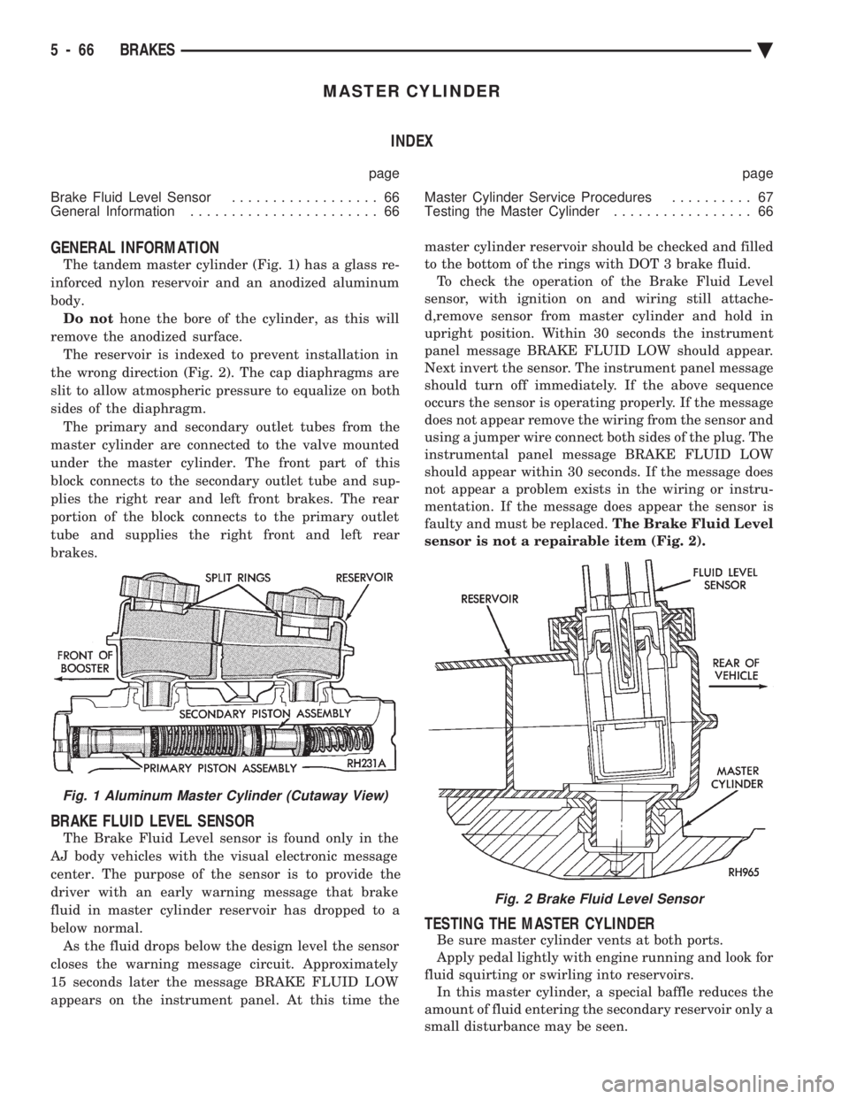
GENERAL INFORMATION
The tandem master cylinder (Fig. 1) has a glass re-
inforced nylon reservoir and an anodized aluminum
body. Do not hone the bore of the cylinder, as this will
remove the anodized surface. The reservoir is indexed to prevent installation in
the wrong direction (Fig. 2). The cap diaphragms are
slit to allow atmospheric pressure to equalize on both
sides of the diaphragm. The primary and secondary outlet tubes from the
master cylinder are connected to the valve mounted
under the master cylinder. The front part of this
block connects to the secondary outlet tube and sup-
plies the right rear and left front brakes. The rear
portion of the block connects to the primary outlet
tube and supplies the right front and left rear
brakes.
BRAKE FLUID LEVEL SENSOR
The Brake Fluid Level sensor is found only in the
AJ body vehicles with the visual electronic message
center. The purpose of the sensor is to provide the
driver with an early warning message that brake
fluid in master cylinder reservoir has dropped to a
below normal. As the fluid drops below the design level the sensor
closes the warning message circuit. Approximately
15 seconds later the message BRAKE FLUID LOW
appears on the instrument panel. At this time the master cylinder reservoir should be checked and filled
to the bottom of the rings with DOT 3 brake fluid. To check the operation of the Brake Fluid Level
sensor, with ignition on and wiring still attache-
d,remove sensor from master cylinder and hold in
upright position. Within 30 seconds the instrument
panel message BRAKE FLUID LOW should appear.
Next invert the sensor. The instrument panel message
should turn off immediately. If the above sequence
occurs the sensor is operating properly. If the message
does not appear remove the wiring from the sensor and
using a jumper wire connect both sides of the plug. The
instrumental panel message BRAKE FLUID LOW
should appear within 30 seconds. If the message does
not appear a problem exists in the wiring or instru-
mentation. If the message does appear the sensor is
faulty and must be replaced. The Brake Fluid Level
sensor is not a repairable item (Fig. 2).
TESTING THE MASTER CYLINDER
Be sure master cylinder vents at both ports.
Apply pedal lightly with engine running and look for
fluid squirting or swirling into reservoirs. In this master cylinder, a special baffle reduces the
amount of fluid entering the secondary reservoir only a
small disturbance may be seen.
Fig. 1 Aluminum Master Cylinder (Cutaway View)
Fig. 2 Brake Fluid Level Sensor
5 - 66 BRAKES Ä
Page 228 of 2438
pared by the (CAB) and used to detect brake system
faults that would require Anti -Lock Braking to be
disabled.The Boost Pressure Transducer is mounted on the
bottom of the hydraulic assembly, (Fig. 1) and moni-
tors booster servo pressure. The Primary Pressure
Transducer is mounted on the left side of the hydrau-
lic assembly and monitors primary master cylinder
pressure.
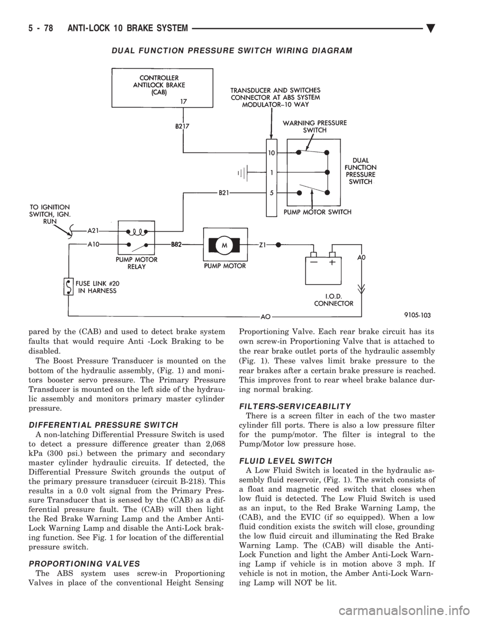
DIFFERENTIAL PRESSURE SWITCH
A non-latching Differential Pressure Switch is used
to detect a pressure difference greater than 2,068
kPa (300 psi.) between the primary and secondary
master cylinder hydraulic circuits. If detected, the
Differential Pressure Switch grounds the output of
the primary pressure transducer (circuit B-218). This
results in a 0.0 volt signal from the Primary Pres-
sure Transducer that is sensed by the (CAB) as a dif-
ferential pressure fault. The (CAB) will then light
the Red Brake Warning Lamp and the Amber Anti-
Lock Warning Lamp and disable the Anti-Lock brak-
ing function. See Fig. 1 for location of the differential
pressure switch.
PROPORTIONING VALVES
The ABS system uses screw-in Proportioning
Valves in place of the conventional Height Sensing Proportioning Valve. Each rear brake circuit has its
own screw-in Proportioning Valve that is attached to
the rear brake outlet ports of the hydraulic assembly
(Fig. 1). These valves limit brake pressure to the
rear brakes after a certain brake pressure is reached.
This improves front to rear wheel brake balance dur-
ing normal braking.
FILTERS-SERVICEABILITY
There is a screen filter in each of the two master
cylinder fill ports. There is also a low pressure filter
for the pump/motor. The filter is integral to the
Pump/Motor low pressure hose.
FLUID LEVEL SWITCH
A Low Fluid Switch is located in the hydraulic as-
sembly fluid reservoir, (Fig. 1). The switch consists of
a float and magnetic reed switch that closes when
low fluid is detected. The Low Fluid Switch is used
as an input, to the Red Brake Warning Lamp, the
(CAB), and the EVIC (if so equipped). When a low
fluid condition exists the switch will close, grounding
the low fluid circuit and illuminating the Red Brake
Warning Lamp. The (CAB) will disable the Anti-
Lock Function and light the Amber Anti-Lock Warn-
ing Lamp if vehicle is in motion above 3 mph. If
vehicle is not in motion, the Amber Anti-Lock Warn-
ing Lamp will NOT be lit.
DUAL FUNCTION PRESSURE SWITCH WIRING DIAGRAM
5 - 78 ANTI-LOCK 10 BRAKE SYSTEM Ä
Page 229 of 2438
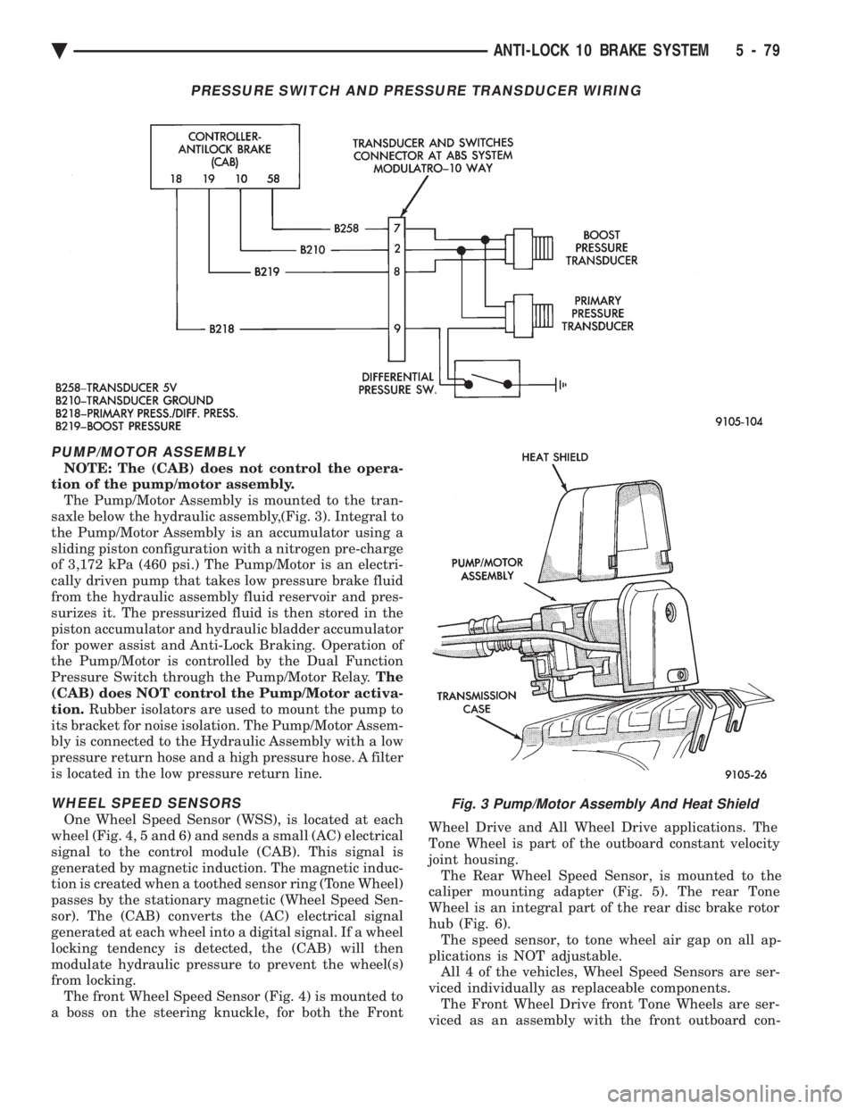
PUMP/MOTOR ASSEMBLY
NOTE: The (CAB) does not control the opera-
tion of the pump/motor assembly. The Pump/Motor Assembly is mounted to the tran-
saxle below the hydraulic assembly,(Fig. 3). Integral to
the Pump/Motor Assembly is an accumulator using a
sliding piston configuration with a nitrogen pre-charge
of 3,172 kPa (460 psi.) The Pump/Motor is an electri-
cally driven pump that takes low pressure brake fluid
from the hydraulic assembly fluid reservoir and pres-
surizes it. The pressurized fluid is then stored in the
piston accumulator and hydraulic bladder accumulator
for power assist and Anti-Lock Braking. Operation of
the Pump/Motor is controlled by the Dual Function
Pressure Switch through the Pump/Motor Relay. The
(CAB) does NOT control the Pump/Motor activa-
tion. Rubber isolators are used to mount the pump to
its bracket for noise isolation. The Pump/Motor Assem-
bly is connected to the Hydraulic Assembly with a low
pressure return hose and a high pressure hose. A filter
is located in the low pressure return line.
WHEEL SPEED SENSORS
One Wheel Speed Sensor (WSS), is located at each
wheel (Fig. 4, 5 and 6) and sends a small (AC) electrical
signal to the control module (CAB). This signal is
generated by magnetic induction. The magnetic induc-
tion is created when a toothed sensor ring (Tone Wheel)
passes by the stationary magnetic (Wheel Speed Sen-
sor). The (CAB) converts the (AC) electrical signal
generated at each wheel into a digital signal. If a wheel
locking tendency is detected, the (CAB) will then
modulate hydraulic pressure to prevent the wheel(s)
from locking. The front Wheel Speed Sensor (Fig. 4) is mounted to
a boss on the steering knuckle, for both the Front Wheel Drive and All Wheel Drive applications. The
Tone Wheel is part of the outboard constant velocity
joint housing. The Rear Wheel Speed Sensor, is mounted to the
caliper mounting adapter (Fig. 5). The rear Tone
Wheel is an integral part of the rear disc brake rotor
hub (Fig. 6). The speed sensor, to tone wheel air gap on all ap-
plications is NOT adjustable. All 4 of the vehicles, Wheel Speed Sensors are ser-
viced individually as replaceable components. The Front Wheel Drive front Tone Wheels are ser-
viced as an assembly with the front outboard con-
Fig. 3 Pump/Motor Assembly And Heat Shield
PRESSURE SWITCH AND PRESSURE TRANSDUCER WIRING
Ä ANTI-LOCK 10 BRAKE SYSTEM 5 - 79
Page 231 of 2438
ABS SYSTEM WIRING SCHEMATIC
Ä ANTI-LOCK 10 BRAKE SYSTEM 5 - 81
Page 234 of 2438
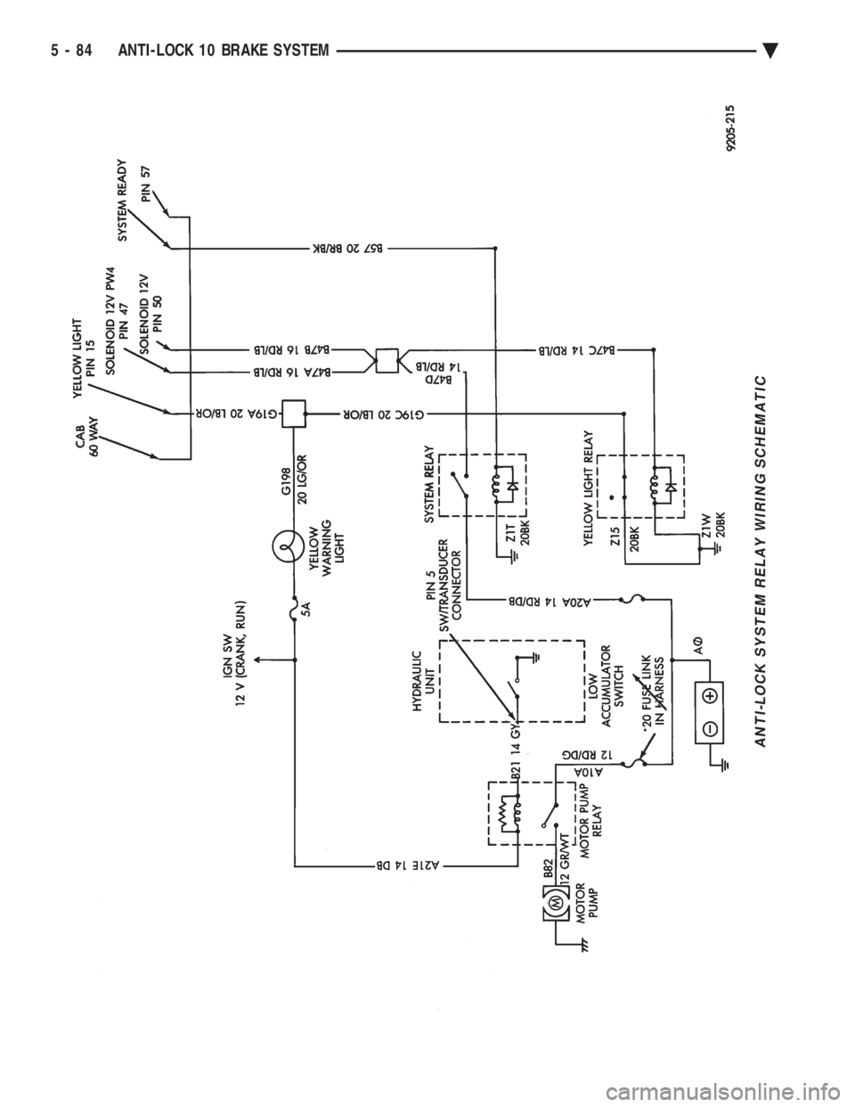
ANTI-LOCK SYSTEM RELAY WIRING SCHEMATIC
5 - 84 ANTI-LOCK 10 BRAKE SYSTEM Ä
Page 240 of 2438
WARNING: FAILURE TO DE-PRESSURIZE THE AC-
CUMULATOR PRIOR TO PERFORMING THIS OPER-
ATION MAY RESULT IN PERSONAL INJURY
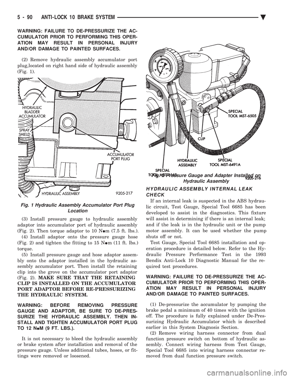
AND/OR DAMAGE TO PAINTED SURFACES. (2) Remove hydraulic assembly accumulator port
plug,located on right hand side of hydraulic assembly
(Fig. 1).
(3) Install pressure gauge to hydraulic assembly
adaptor into accumulator port of hydraulic assembly
(Fig. 2). Then torque adaptor to 10 N Im (7.5 ft. lbs.).
(4) Install adaptor onto the pressure gauge hose
(Fig. 2) and tighten the fitting to 15 N Im (11 ft. lbs.)
torque. (5) Install pressure gauge and hose adaptor assem-
bly onto the adaptor installed in the hydraulic as-
sembly accumulator port. Then install the retaining
clip into the grove on the accumulator port adaptor
(Fig. 2). MAKE SURE THAT THE RETAINING
CLIP IS INSTALLED ON THE ACCUMULATOR
PORT ADAPTOR BEFORE RE-PRESSURIZING
THE HYDRAULIC SYSTEM.
WARNING: BEFORE REMOVING PRESSURE
GAUGE AND ADAPTOR, BE SURE TO DE-PRES-
SURIZE THE HYDRAULIC ASSEMBLY. THEN IN-
STALL AND TIGHTEN ACCUMULATOR PORT PLUG
TO 12 N IM (9 FT. LBS.).
It is not necessary to bleed the hydraulic assembly
or brake system after installation and removal of the
pressure gauge. Unless additional tubes, hoses, or fit-
tings were removed or loosened.
HYDRAULIC ASSEMBLY INTERNAL LEAK
CHECK
If an internal leak is suspected in the ABS hydrau-
lic circuit, Test Gauge, Special Tool 6685 has been
developed to assist in the diagnostics. This fixture
will assist in determining if there is an internal leak;
and if the leak is in the hydraulic unit or the pump
motor assembly. It can be used whether the pump
shuts off or not. Test Gauge, Special Tool 6685 installation and op-
eration procedure is detailed below. Refer to the Hy-
draulic Pressure Performance Test in the 1993
Bendix Anti-Lock 10 Diagnostic Manual for the re-
quired test procedures.
WARNING: FAILURE TO DE-PRESSURIZE THE AC-
CUMULATOR PRIOR TO PERFORMING THIS OPER-
ATION MAY RESULT IN PERSONAL INJURY
AND/OR DAMAGE TO PAINTED SURFACES.
(1) De-pressurize the accumulator by pumping the
brake pedal a minimum of 40 times with the ignition
off. The procedure is fully explained under De-Pres-
surizing Hydraulic Accumulator which is described
earlier in this System Diagnosis Section. (2) Remove wiring harness connector from dual
function pressure switch on bottom of hydraulic as-
sembly. Connect wiring harness from Test Gauge,
Special Tool 6685 into wiring harness connector re-
moved from dual function pressure switch.Fig. 1 Hydraulic Assembly Accumulator Port Plug Location
Fig. 2 Pressure Gauge and Adapter Installed onHydraulic Assembly
5 - 90 ANTI-LOCK 10 BRAKE SYSTEM Ä