timing belt CHEVROLET DYNASTY 1993 Owner's Guide
[x] Cancel search | Manufacturer: CHEVROLET, Model Year: 1993, Model line: DYNASTY, Model: CHEVROLET DYNASTY 1993Pages: 2438, PDF Size: 74.98 MB
Page 1650 of 2438
PISTON RINGSÐINSTALLATION
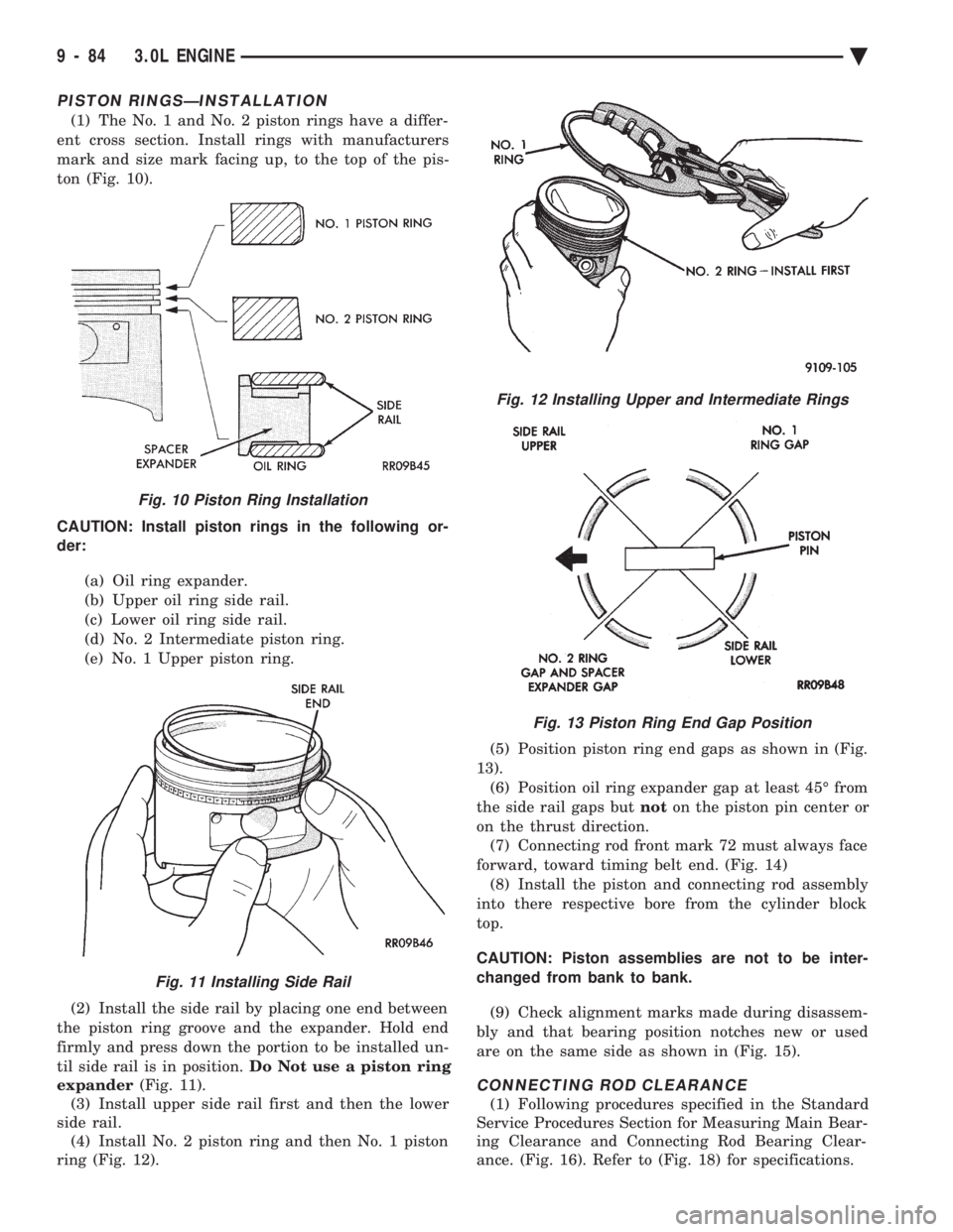
(1) The No. 1 and No. 2 piston rings have a differ-
ent cross section. Install rings with manufacturers
mark and size mark facing up, to the top of the pis-
ton (Fig. 10).
CAUTION: Install piston rings in the following or-
der:
(a) Oil ring expander.
(b) Upper oil ring side rail.
(c) Lower oil ring side rail.
(d) No. 2 Intermediate piston ring.
(e) No. 1 Upper piston ring.
(2) Install the side rail by placing one end between
the piston ring groove and the expander. Hold end
firmly and press down the portion to be installed un-
til side rail is in position. Do Not use a piston ring
expander (Fig. 11).
(3) Install upper side rail first and then the lower
side rail. (4) Install No. 2 piston ring and then No. 1 piston
ring (Fig. 12). (5) Position piston ring end gaps as shown in (Fig.
13). (6) Position oil ring expander gap at least 45É from
the side rail gaps but noton the piston pin center or
on the thrust direction. (7) Connecting rod front mark 72 must always face
forward, toward timing belt end. (Fig. 14) (8) Install the piston and connecting rod assembly
into there respective bore from the cylinder block
top.
CAUTION: Piston assemblies are not to be inter-
changed from bank to bank.
(9) Check alignment marks made during disassem-
bly and that bearing position notches new or used
are on the same side as shown in (Fig. 15).
CONNECTING ROD CLEARANCE
(1) Following procedures specified in the Standard
Service Procedures Section for Measuring Main Bear-
ing Clearance and Connecting Rod Bearing Clear-
ance. (Fig. 16). Refer to (Fig. 18) for specifications.
Fig. 10 Piston Ring Installation
Fig. 11 Installing Side Rail
Fig. 12 Installing Upper and Intermediate Rings
Fig. 13 Piston Ring End Gap Position
9 - 84 3.0L ENGINE Ä
Page 1654 of 2438
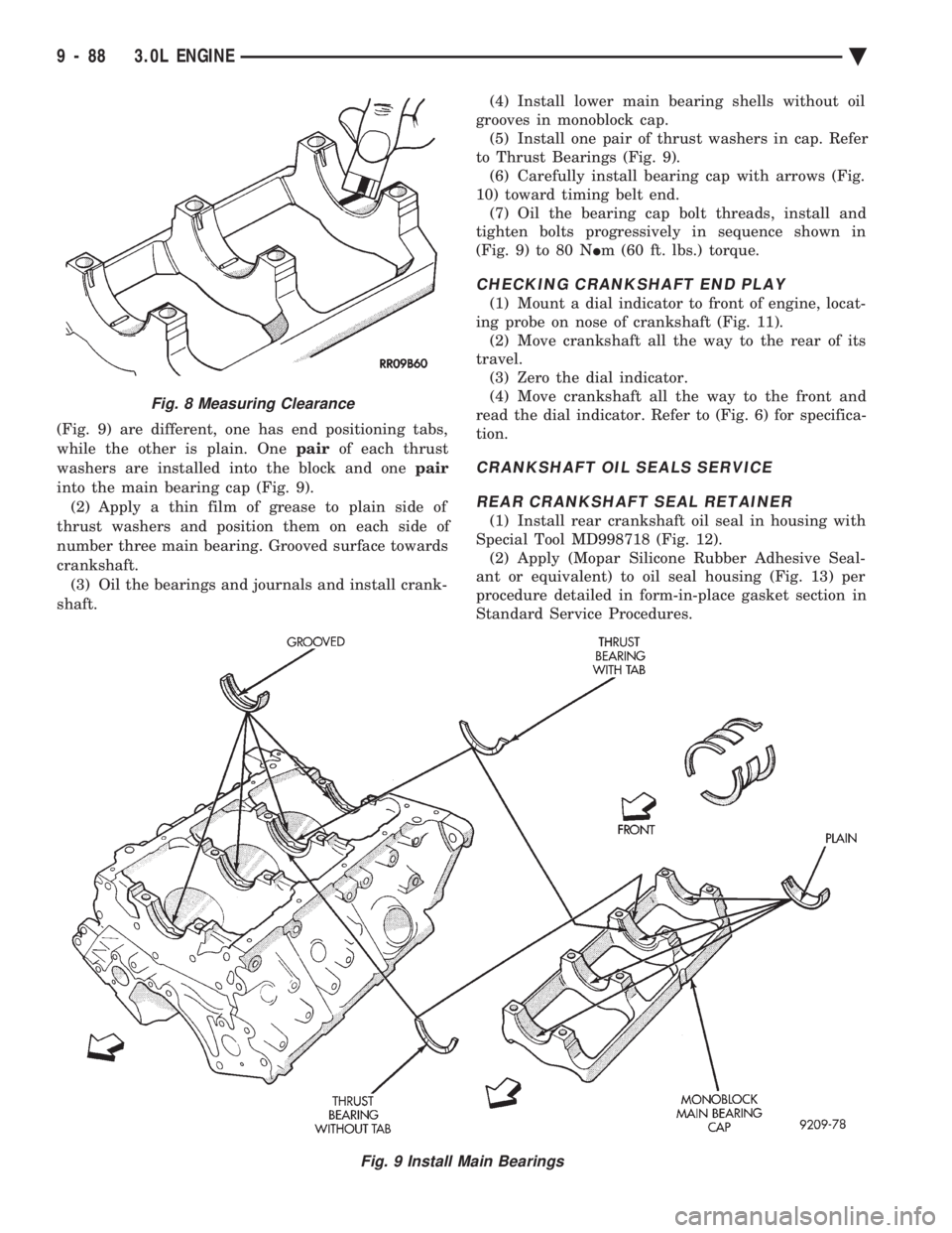
(Fig. 9) are different, one has end positioning tabs,
while the other is plain. One pairof each thrust
washers are installed into the block and one pair
into the main bearing cap (Fig. 9). (2) Apply a thin film of grease to plain side of
thrust washers and position them on each side of
number three main bearing. Grooved surface towards
crankshaft. (3) Oil the bearings and journals and install crank-
shaft. (4) Install lower main bearing shells without oil
grooves in monoblock cap. (5) Install one pair of thrust washers in cap. Refer
to Thrust Bearings (Fig. 9). (6) Carefully install bearing cap with arrows (Fig.
10) toward timing belt end. (7) Oil the bearing cap bolt threads, install and
tighten bolts progressively in sequence shown in
(Fig. 9) to 80 N Im (60 ft. lbs.) torque.
CHECKING CRANKSHAFT END PLAY
(1) Mount a dial indicator to front of engine, locat-
ing probe on nose of crankshaft (Fig. 11). (2) Move crankshaft all the way to the rear of its
travel. (3) Zero the dial indicator.
(4) Move crankshaft all the way to the front and
read the dial indicator. Refer to (Fig. 6) for specifica-
tion.
CRANKSHAFT OIL SEALS SERVICE
REAR CRANKSHAFT SEAL RETAINER
(1) Install rear crankshaft oil seal in housing with
Special Tool MD998718 (Fig. 12). (2) Apply (Mopar Silicone Rubber Adhesive Seal-
ant or equivalent) to oil seal housing (Fig. 13) per
procedure detailed in form-in-place gasket section in
Standard Service Procedures.
Fig. 9 Install Main Bearings
Fig. 8 Measuring Clearance
9 - 88 3.0L ENGINE Ä
Page 1658 of 2438

OIL PAN
The oil pan is made of sheet metal and is provided
with a baffle-plate to prevent fluctuations in the oil
level while the vehicle is running (Fig. 2).
OIL PAN SEALING AND INSTALLATION
Oil pan to crankcase sealing is provided with Mo-
par Silicone Rubber Adhesive Sealant or equivalent
gasket material. See Form-In-Place Gaskets in Stan-
dard Service Procedures. (1) Apply sealant as shown in (Fig. 3).
(2) Install pan and tighten screws to 6 N Im (50 in.
lbs.) in sequence shown in (Fig. 4).
OIL PUMP SERVICE
The oil pump assembly is mounted on the timing
belt end of the cylinder block with the inner pump
rotor indexed and installed on the crankshaft nose.
(Fig. 5). The oil pump case also retains the crankshaft front
oil seal and provides oil pan front end closure.
REMOVAL
Remove accessory drive system. Refer to Accessory
Drive Service in this group. Remove 5 bolts that attach oil pump to block (Fig.
6).
INSPECTION OIL PUMP
(1) Check oil pump case for damage and remove
rear cover. (2) Remove pump rotors and inspect case for exces-
sive wear. (3) Measure clearance between case and inner ro-
tor (Fig. 8). (4) Insert the rotor into the oil pump case (Figs. 9
and 10) and measure clearance with a feeler gauge
as indicated.
Fig. 2 Oil Pan
Fig. 3 Oil Pan Sealing
Fig. 4 Oil Pan Screw Tightening Sequence
Fig. 5 Oil Pump-Installed
Fig. 6 Oil Pump Assembly
9 - 92 3.0L ENGINE Ä
Page 1675 of 2438
(2) Clean varnish deposits from inside of tappet
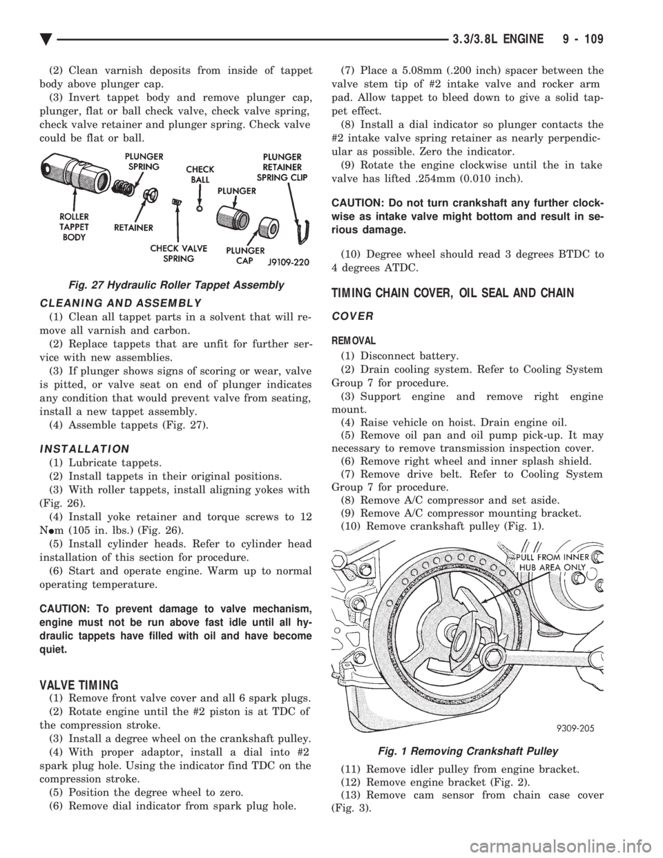
body above plunger cap. (3) Invert tappet body and remove plunger cap,
plunger, flat or ball check valve, check valve spring,
check valve retainer and plunger spring. Check valve
could be flat or ball.
CLEANING AND ASSEMBLY
(1) Clean all tappet parts in a solvent that will re-
move all varnish and carbon. (2) Replace tappets that are unfit for further ser-
vice with new assemblies. (3) If plunger shows signs of scoring or wear, valve
is pitted, or valve seat on end of plunger indicates
any condition that would prevent valve from seating,
install a new tappet assembly. (4) Assemble tappets (Fig. 27).
INSTALLATION
(1) Lubricate tappets.
(2) Install tappets in their original positions.
(3) With roller tappets, install aligning yokes with
(Fig. 26). (4) Install yoke retainer and torque screws to 12
N Im (105 in. lbs.) (Fig. 26).
(5) Install cylinder heads. Refer to cylinder head
installation of this section for procedure. (6) Start and operate engine. Warm up to normal
operating temperature.
CAUTION: To prevent damage to valve mechanism,
engine must not be run above fast idle until all hy-
draulic tappets have filled with oil and have become
quiet.
VALVE TIMING
(1) Remove front valve cover and all 6 spark plugs.
(2) Rotate engine until the #2 piston is at TDC of
the compression stroke. (3) Install a degree wheel on the crankshaft pulley.
(4) With proper adaptor, install a dial into #2
spark plug hole. Using the indicator find TDC on the
compression stroke. (5) Position the degree wheel to zero.
(6) Remove dial indicator from spark plug hole. (7) Place a 5.08mm (.200 inch) spacer between the
valve stem tip of #2 intake valve and rocker arm
pad. Allow tappet to bleed down to give a solid tap-
pet effect. (8) Install a dial indicator so plunger contacts the
#2 intake valve spring retainer as nearly perpendic-
ular as possible. Zero the indicator. (9) Rotate the engine clockwise until the in take
valve has lifted .254mm (0.010 inch).
CAUTION: Do not turn crankshaft any further clock-
wise as intake valve might bottom and result in se-
rious damage.
(10) Degree wheel should read 3 degrees BTDC to
4 degrees ATDC.
TIMING CHAIN COVER, OIL SEAL AND CHAIN
COVER
REMOVAL
(1) Disconnect battery.
(2) Drain cooling system. Refer to Cooling System
Group 7 for procedure. (3) Support engine and remove right engine
mount. (4) Raise vehicle on hoist. Drain engine oil.
(5) Remove oil pan and oil pump pick-up. It may
necessary to remove transmission inspection cover. (6) Remove right wheel and inner splash shield.
(7) Remove drive belt. Refer to Cooling System
Group 7 for procedure. (8) Remove A/C compressor and set aside.
(9) Remove A/C compressor mounting bracket.
(10) Remove crankshaft pulley (Fig. 1).
(11) Remove idler pulley from engine bracket.
(12) Remove engine bracket (Fig. 2).
(13) Remove cam sensor from chain case cover
(Fig. 3).
Fig. 27 Hydraulic Roller Tappet Assembly
Fig. 1 Removing Crankshaft Pulley
Ä 3.3/3.8L ENGINE 9 - 109
Page 1677 of 2438
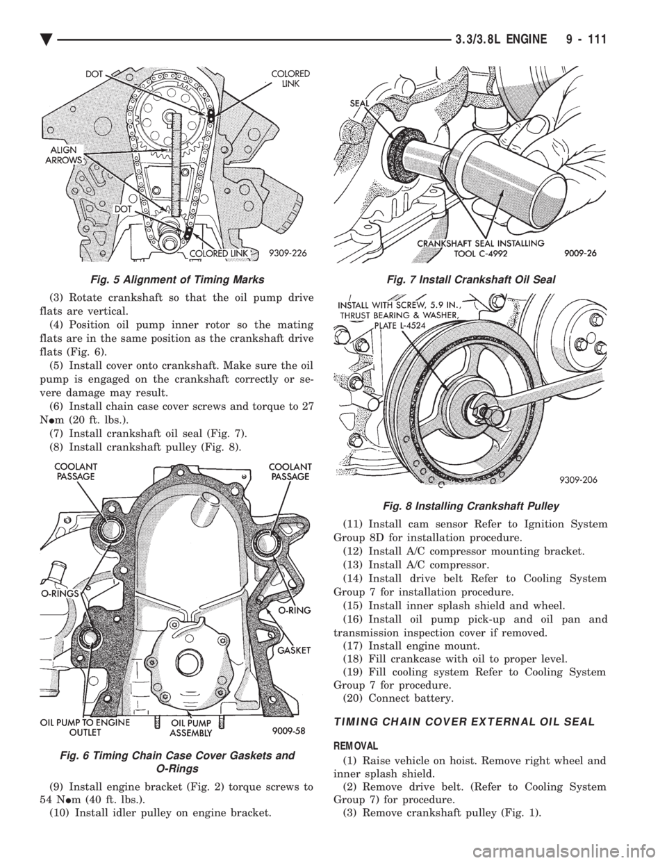
(3) Rotate crankshaft so that the oil pump drive
flats are vertical. (4) Position oil pump inner rotor so the mating
flats are in the same position as the crankshaft drive
flats (Fig. 6). (5) Install cover onto crankshaft. Make sure the oil
pump is engaged on the crankshaft correctly or se-
vere damage may result. (6) Install chain case cover screws and torque to 27
N Im (20 ft. lbs.).
(7) Install crankshaft oil seal (Fig. 7).
(8) Install crankshaft pulley (Fig. 8).
(9) Install engine bracket (Fig. 2) torque screws to
54 N Im (40 ft. lbs.).
(10) Install idler pulley on engine bracket. (11) Install cam sensor Refer to Ignition System
Group 8D for installation procedure. (12) Install A/C compressor mounting bracket.
(13) Install A/C compressor.
(14) Install drive belt Refer to Cooling System
Group 7 for installation procedure. (15) Install inner splash shield and wheel.
(16) Install oil pump pick-up and oil pan and
transmission inspection cover if removed. (17) Install engine mount.
(18) Fill crankcase with oil to proper level.
(19) Fill cooling system Refer to Cooling System
Group 7 for procedure. (20) Connect battery.
TIMING CHAIN COVER EXTERNAL OIL SEAL
REMOVAL
(1) Raise vehicle on hoist. Remove right wheel and
inner splash shield. (2) Remove drive belt. (Refer to Cooling System
Group 7) for procedure. (3) Remove crankshaft pulley (Fig. 1).
Fig. 5 Alignment of Timing Marks
Fig. 6 Timing Chain Case Cover Gaskets and O-Rings
Fig. 7 Install Crankshaft Oil Seal
Fig. 8 Installing Crankshaft Pulley
Ä 3.3/3.8L ENGINE 9 - 111
Page 1678 of 2438
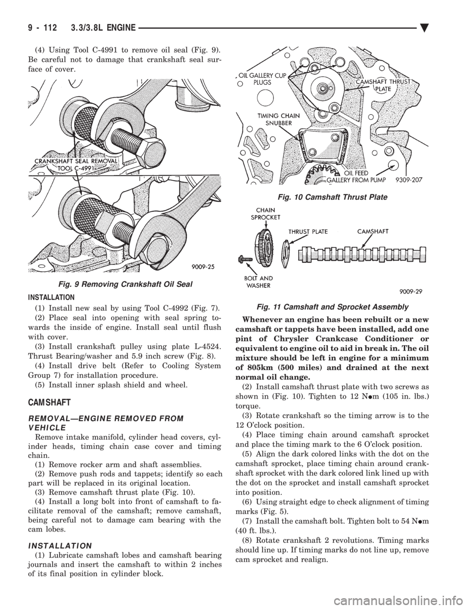
(4) Using Tool C-4991 to remove oil seal (Fig. 9).
Be careful not to damage that crankshaft seal sur-
face of cover.
INSTALLATION (1) Install new seal by using Tool C-4992 (Fig. 7).
(2) Place seal into opening with seal spring to-
wards the inside of engine. Install seal until flush
with cover. (3) Install crankshaft pulley using plate L-4524.
Thrust Bearing/washer and 5.9 inch screw (Fig. 8). (4) Install drive belt (Refer to Cooling System
Group 7) for installation procedure. (5) Install inner splash shield and wheel.
CAMSHAFT
REMOVALÐENGINE REMOVED FROM VEHICLE
Remove intake manifold, cylinder head covers, cyl-
inder heads, timing chain case cover and timing
chain. (1) Remove rocker arm and shaft assemblies.
(2) Remove push rods and tappets; identify so each
part will be replaced in its original location. (3) Remove camshaft thrust plate (Fig. 10).
(4) Install a long bolt into front of camshaft to fa-
cilitate removal of the camshaft; remove camshaft,
being careful not to damage cam bearing with the
cam lobes.
INSTALLATION
(1) Lubricate camshaft lobes and camshaft bearing
journals and insert the camshaft to within 2 inches
of its final position in cylinder block. Whenever an engine has been rebuilt or a new
camshaft or tappets have been installed, add one
pint of Chrysler Crankcase Conditioner or
equivalent to engine oil to aid in break in. The oil
mixture should be left in engine for a minimum
of 805km (500 miles) and drained at the next
normal oil change. (2) Install camshaft thrust plate with two screws as
shown in (Fig. 10). Tighten to 12 N Im (105 in. lbs.)
torque. (3) Rotate crankshaft so the timing arrow is to the
12 O'clock position. (4) Place timing chain around camshaft sprocket
and place the timing mark to the 6 O'clock position. (5) Align the dark colored links with the dot on the
camshaft sprocket, place timing chain around crank-
shaft sprocket with the dark colored link lined up with
the dot on the sprocket and install camshaft sprocket
into position. (6) Using straight edge to check alignment of timing
marks (Fig. 5). (7) Install the camshaft bolt. Tighten bolt to 54 N Im
(40 ft. lbs.). (8) Rotate crankshaft 2 revolutions. Timing marks
should line up. If timing marks do not line up, remove
cam sprocket and realign.
Fig. 9 Removing Crankshaft Oil Seal
Fig. 10 Camshaft Thrust Plate
Fig. 11 Camshaft and Sprocket Assembly
9 - 112 3.3/3.8L ENGINE Ä
Page 1811 of 2438
the PCM to store diagnostic trouble codes for other
systems. For example, a fuel pressure problem will not
register a fault directly, but could cause a rich or lean
condition. This could cause the PCM to store an oxygen
sensor diagnostic trouble code. Fuel Pressure - The vacuum assisted fuel pressure
regulator controls fuel system pressure. The PCM
cannot detect a clogged fuel pump inlet filter, clogged
in-line fuel filter, stuck open regulator, or a pinched
fuel supply or return line. However, these could result
in a rich or lean condition causing the PCM to store an
oxygen sensor diagnostic trouble code. Secondary Ignition Circuit - The PCM cannot
detect an inoperative ignition coil, fouled or worn spark
plugs, ignition cross firing, or open spark plug cables. Engine Timing - The PCM cannot detect an incor-
rectly indexed timing belt, camshaft sprocket and
crankshaft sprocket. However, these could result in a
rich or lean condition causing the PCM to store an
oxygen sensor diagnostic trouble code. Cylinder Compression - The PCM cannot detect
uneven, low, or high engine cylinder compression. Exhaust System - The PCM cannot detect a
plugged, restricted or leaking exhaust system. Fuel Injector Mechanical Malfunctions - The
PCM cannot determine if a fuel injector is clogged, the
needle is sticking or if the wrong injector is installed.
However, these could result in a rich or lean condition
causing the PCM to store an oxygen sensor diagnostic
trouble code. Excessive Oil Consumption - Although the PCM
monitors exhaust stream oxygen content when the
system is in closed loop, it cannot determine excessive
oil consumption. Throttle Body Air Flow - The PCM cannot detect a
clogged or restricted air cleaner inlet or filter element. Evaporative System - The PCM cannot detect a
disconnected (open vacuum line) restricted, plugged or
loaded evaporative purge canister. Vacuum Assist - The PCM cannot detect leaks or
restrictions in the vacuum circuits of vacuum assisted
engine control system devices. However, these could
cause the PCM to store a MAP sensor diagnostic
trouble code and cause a high idle condition. PCM System Ground - The PCM cannot determine
a poor system ground. However, one or more diagnostic
trouble codes may be generated as a result of this
condition. PCM Connector Engagement - The PCM may not
be able to determine spread or damaged connector
pins. However, it might store diagnostic trouble codes
as a result of spread connector pins.HIGH AND LOW LIMITS
The PCM compares input signal voltages from each
input device with established high and low limits for the
device. If the input voltage is not within limits and other
criteria are met, the PCM stores a diagnostic trouble code
in memory. Other diagnostic trouble code criteria might
include engine RPM limits or input voltages from other
sensors or switches that must be present before verifying
a diagnostic trouble code condition.
DIAGNOSTIC TROUBLE CODES
A diagnostic trouble code indicates the powertrain
control module (PCM) has recognized an abnormal
condition in the system. Abnormal conditions are usu-
ally shorted or open circuits.
The technician can display diagnostic trouble codes in
two ways. The first way is to cycle the ignition switch and
count the number of times the malfunction indicator lamp
(check engine lamp on the instrument panel) flashes on
and off. The DRBII scan tool provides the second method
of displaying diagnostic trouble codes. Diagnostic trouble
codes indicate the results of a circuit failure, but do not
directly identify the failed component.
For a list of Diagnostic Trouble Codes, refer to
the charts at the end of this section.
OBTAINING DIAGNOSTIC TROUBLE CODES
USING DRBII SCAN TOOL
WARNING: APPLY PARKING BRAKE AND/OR BLOCK
WHEELS BEFORE PERFORMING ANY TEST ON AN
OPERATING ENGINE. (1) Connect DRBII scan tool to the data link (diag-
nostic) connector located in the engine compartment,
next to the PCM (Fig. 1). (2) If possible, start the engine and cycle the A/C
switch if applicable. Shut off the engine. (3)
Turn the ignition switch on, access Read Fault
Screen. Record all the diagnostic trouble codes shown on
the DRBII scan tool. [Observe the malfunction indicator
lamp (check engine lamp) on the instrument panel. The
lamp should light for 2 seconds then go out (bulb check)].
To erase diagnostic trouble codes, use the Erase
Trouble Code data screen on the DRBII scan tool.
USING THE MALFUNCTION INDICATOR LAMP (1) Cycle the ignition key On - Off - On - Off - On
within 5 seconds. (2) Count the number of times the malfunction indi-
cator lamp (check engine lamp on the instrument
panel) flashes on and off. The number of flashes
represents the trouble code. There is a slight pause be-
Ä FUEL SYSTEMS 14 - 71