oil CHEVROLET DYNASTY 1993 Service Manual
[x] Cancel search | Manufacturer: CHEVROLET, Model Year: 1993, Model line: DYNASTY, Model: CHEVROLET DYNASTY 1993Pages: 2438, PDF Size: 74.98 MB
Page 2362 of 2438
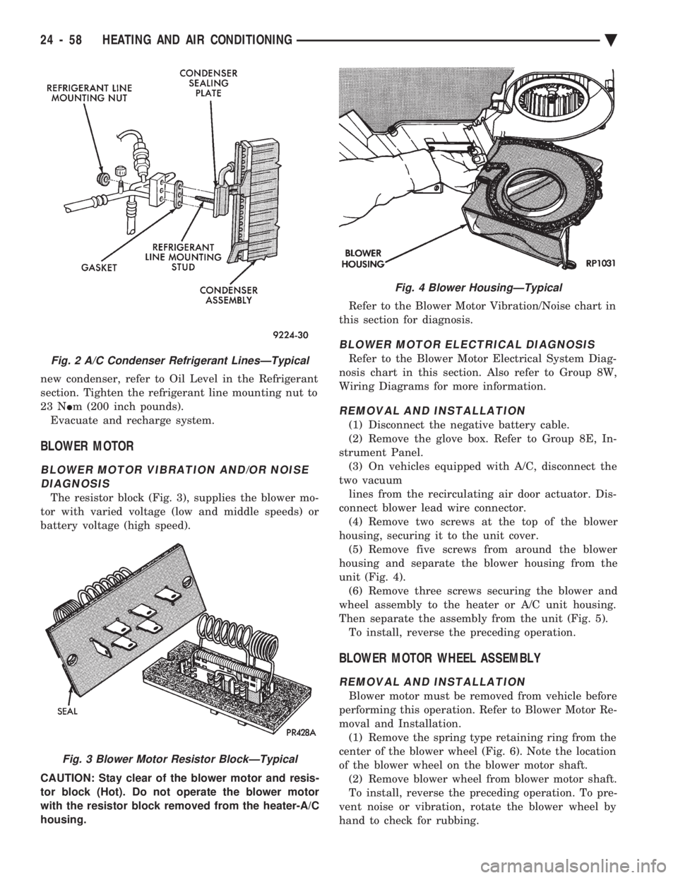
new condenser, refer to Oil Level in the Refrigerant
section. Tighten the refrigerant line mounting nut to
23 N Im (200 inch pounds).
Evacuate and recharge system.
BLOWER MOTOR
BLOWER MOTOR VIBRATION AND/OR NOISE DIAGNOSIS
The resistor block (Fig. 3), supplies the blower mo-
tor with varied voltage (low and middle speeds) or
battery voltage (high speed).
CAUTION: Stay clear of the blower motor and resis-
tor block (Hot). Do not operate the blower motor
with the resistor block removed from the heater-A/C
housing. Refer to the Blower Motor Vibration/Noise chart in
this section for diagnosis.
BLOWER MOTOR ELECTRICAL DIAGNOSIS
Refer to the Blower Motor Electrical System Diag-
nosis chart in this section. Also refer to Group 8W,
Wiring Diagrams for more information.
REMOVAL AND INSTALLATION
(1) Disconnect the negative battery cable.
(2) Remove the glove box. Refer to Group 8E, In-
strument Panel. (3) On vehicles equipped with A/C, disconnect the
two vacuum lines from the recirculating air door actuator. Dis-
connect blower lead wire connector. (4) Remove two screws at the top of the blower
housing, securing it to the unit cover. (5) Remove five screws from around the blower
housing and separate the blower housing from the
unit (Fig. 4). (6) Remove three screws securing the blower and
wheel assembly to the heater or A/C unit housing.
Then separate the assembly from the unit (Fig. 5). To install, reverse the preceding operation.
BLOWER MOTOR WHEEL ASSEMBLY
REMOVAL AND INSTALLATION
Blower motor must be removed from vehicle before
performing this operation. Refer to Blower Motor Re-
moval and Installation. (1) Remove the spring type retaining ring from the
center of the blower wheel (Fig. 6). Note the location
of the blower wheel on the blower motor shaft. (2) Remove blower wheel from blower motor shaft.
To install, reverse the preceding operation. To pre-
vent noise or vibration, rotate the blower wheel by
hand to check for rubbing.
Fig. 2 A/C Condenser Refrigerant LinesÐTypical
Fig. 3 Blower Motor Resistor BlockÐTypical
Fig. 4 Blower HousingÐTypical
24 - 58 HEATING AND AIR CONDITIONING Ä
Page 2366 of 2438
AA BODY PROCEDURE
WARNING: IF EQUIPPED WITH A/C, THE REFRIG-
ERATION SYSTEM MUST BE COMPLETELY EMPTY
BEFORE PROCEEDING WITH THIS OPERATION. Refer to Group 8E and Group 23 for component re-
moval and installation when performing this opera-
tion. (1) Perform steps 1 through 7 of Blower Motor re-
moval and installation. (2) Remove relay panel above glove compartment
opening. (3) Disconnect the A/C vacuum line connector and
radio noise capacitor connectors. (4) Remove left windshield pillar trim cover.
(5) Remove left lower side cowl trim cover.
(6) Remove hood release handle mechanism attach-
ing screws. (7) Remove steering column trim covers.
(8) Disconnect parking brake release mechanism
connecting rod. Gain access through fuse panel open-
ing. (9) Remove lower left instrument panel silencer.
(10) Remove lower left instrument panel reinforce-
ment. (11) Remove instrument panel center (radio) bezel.
(12) Remove forward floor console.
(13) Remove the radio.
(14) Remove the heater-A/C control.
(15) Remove cigar lighter.
(16) Remove message center/trip computer, if
equipped. (17) Disconnect side window demister tubes from
top of heat A/C unit. (18) Remove steering column upper attaching bolts
and allow the steering wheel to rest on the driver
seat cushion. (19) Remove upper instrument panel (defroster
outlet) cover. (20) Remove upper instrument panel attaching
screws from below the windshield opening. (21) Loosen (do not remove) the left lower cowl in-
strument panel attaching screw. (22) Remove the right lower cowl instrument panel
attaching screw.
CAUTION: Protect the passenger seat cover from
soiling or damage using a suitable cover.
(23) Carefully pull the right side of the instrument
panel away from the vehicle. Allow the instrument
panel to rest on the passenger seat cushion.
CAUTION: Before proceeding with the next opera-
tion, review the Safety Precautions and Warnings at
the front of this Group. (24) From the engine compartment, drain the cool-
ing system and disconnect the heater hoses from the
heater core nipples. Plug the nipples to avoid spilling
coolant inside the vehicle. (25) Disconnect the refrigerant lines from the ex-
pansion-valve at the dash panel on the right side of
the vehicle. Seal the refrigerant lines to prevent con-
tamination. (26) Remove the expansion valve from the evapo-
rator plate. Seal the valve to avoid contamination. (27) Remove the condensate drain tube.
(28) Remove heater-A/C unit to dash panel attach-
ing nuts. (29) From inside the vehicle, pull rearward on the
heater-A/C unit to clear the dash panel silencer and
remove the unit from the vehicle. To install, reverse the preceding operation. Refill
cooling system and test for leaks. Evacuate and
charge the refrigerant system and test overall perfor-
mance.
AG, AJ BODY PROCEDURE
WARNING: IF EQUIPPED WITH A/C, THE REFRIG-
ERATION SYSTEM MUST BE COMPLETELY EMPTY
BEFORE PROCEEDING WITH THIS OPERATION.
(1) Disconnect the battery negative cable.
(2) Drain the coolant from cooling system. Refer to
Group 7, Cooling System. (3) Remove the air conditioner expansion valve (if
equipped). (4) Disconnect the heater hoses from heater core.
Then plug or cap the tubes on heater core. This will
prevent spilling coolant into the interior of vehicle
during unit removal. (5) Remove the condensate drain tube.
(6) Disconnect the A/C-heater vacuum supply line
from vacuum supply nipple (in the engine compart-
ment). (7) Remove the four A/C-heater assembly-to-dash
panel attaching nuts. (8) Remove the passenger side front seat. Refer to
Group 23, Body. (9) Remove the kick panel/sill cover at right door
opening. (10) Remove the body computer (Fig. 6) located at
the lower right section of the right front door pillar. (11) Remove the glove box assembly. Refer to
Group 8E, Instrument Panel. (12) Remove the carpeted panels from both sides of
the console. (13) Un-clip the radio antenna cable from the
metal support (Fig. 6) located behind and below the
glove box opening. (14) Instrument panel removal is not necessary to
remove the A/C-heater assembly from the vehicle.
24 - 62 HEATING AND AIR CONDITIONING Ä
Page 2368 of 2438

(3) To remove the top cover from the A/C-heater
case, the crank arm must be removed (Fig. 2).
(4) Disconnect the vacuum lines from the defroster
and panel mode vacuum actuators and position them
out of the way. (5) Remove three heater-A/C unit cover attaching
screws going upward at the defroster outlet chamber. (6) Remove two heater-A/C unit cover attaching
screws going upward at the air inlet plenum. (7) Remove eleven heater-A/C unit cover attaching
screws going downward into the housing. Then lift
the cover from the heater-A/C unit. (Fig. 3).
To reassemble, lower the heater-A/C unit cover
into place. Then guide the panel air mode door pivot
shaft into its socket and reverse the preceding oper-
ation.BLEND-AIR DOOR
REMOVAL AND INSTALLATION
The following operation requires the removal of the
heater-A/C unit assembly from the vehicle. Refer to
Heater-A/C Unit Assembly removal and installation
in this Group. (1) Remove Heater-A/C unit top cover.
(2) Remove the nut from bottom of the blend-air
door pivot shaft and lift the blend-air door from the
heater-A/C unit housing. (Fig. 4).
To install, reverse the preceding operation.
HEATER CORE
REMOVAL AND INSTALLATION
Refer to Heater A/C Unit Recondition in this
Group.
EVAPORATOR COIL
REMOVAL AND INSTALLATION
Refer to Heater A/C Unit Recondition in this
Group.
CONDENSATE DRAIN TUBE
Condensation that accumulates on the bottom of
the evaporator housing is drained from a rubber tube
through the dash panel and on to the ground. This
tube must be kept open to prevent condensate water
from collecting in the bottom of the heater A/C unit
housing. The tapered end of the drain tube is designed to
keep contaminants from entering the heater A/C unit
housing. If the tube is pinched or blocked, condensate
cannot drain, causing water to back up and spill into
Fig. 2 Blend-Air Door Crank Linkage Removal
Fig. 3 Heater-A/C Unit Cover Removal and Installation
Fig. 4 Blend-Air Door Removal and Installation
24 - 64 HEATING AND AIR CONDITIONING Ä
Page 2421 of 2438
TORQUE REFERENCES
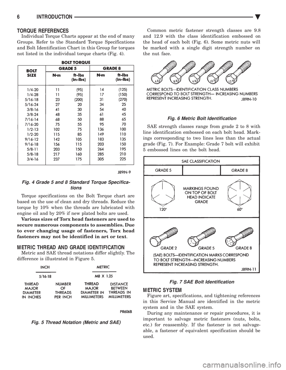
Individual Torque Charts appear at the end of many
Groups. Refer to the Standard Torque Specifications
and Bolt Identification Chart in this Group for torques
not listed in the individual torque charts (Fig. 4).
Torque specifications on the Bolt Torque chart are
based on the use of clean and dry threads. Reduce the
torque by 10% when the threads are lubricated with
engine oil and by 20% if new plated bolts are used. Various sizes of Torx head fasteners are used to
secure numerous components to assemblies. Due
to ever changing usage of fasteners, Torx head
fasteners may not be identified in art or text .
METRIC THREAD AND GRADE IDENTIFICATION
Metric and SAE thread notations differ slightly. The
difference is illustrated in Figure 5. Common metric fastener strength classes are 9.8
and 12.9 with the class identification embossed on
the head of each bolt (Fig. 6). Some metric nuts will
be marked with a single digit strength number on
the nut face.
SAE strength classes range from grade 2 to 8 with
line identification embossed on each bolt head. Mark-
ings corresponding to two lines less than the actual
grade (Fig. 7). For Example: Grade 7 bolt will exhibit
5 embossed lines on the bolt head.
METRIC SYSTEM
Figure art, specifications, and tightening references
in this Service Manual are identified in the metric
system and in the SAE system. During any maintenance or repair procedures, it is
important to salvage metric fasteners (nuts, bolts,
etc.) for reassembly. If the fastener is not salvage-
able, a fastener of equivalent specification should be
used.
Fig. 6 Metric Bolt Identification
Fig. 7 SAE Bolt Identification
Fig. 4 Grade 5 and 8 Standard Torque Specifica- tions
Fig. 5 Thread Notation (Metric and SAE)
6 INTRODUCTION Ä