fig. 78 CHRYSLER CARAVAN 2002 Service Manual
[x] Cancel search | Manufacturer: CHRYSLER, Model Year: 2002, Model line: CARAVAN, Model: CHRYSLER CARAVAN 2002Pages: 2399, PDF Size: 57.96 MB
Page 441 of 2399

INSTALLATION
(1) Install the Generator Decoupler to the genera-
tor shaft.
(2) Use Special Tool #8433 (Fig. 20) to tighten the
Generator Decoupler (Fig. 21). Refer to the torque
chart for the proper torque.
(3) Install the Air Box, refer to the Engine section
for more information.
(4) Raise vehicle and support.
(5) Install accessory drive belt, refer to the Cooling
System section for proper procedures (Fig. 18).
(6) Install the right front lower splash shield.
(7) Lower vehicle.
(8) Connect battery negative cable.
VOLTAGE REGULATOR
DESCRIPTION
The Electronic Voltage Regulator (EVR) is not a
separate component. It is actually a voltage regulat-
ing circuit located within the Powertrain Control
Module (PCM). The EVR is not serviced separately. If
replacement is necessary, the PCM must be replaced.
OPERATION
The amount of DC current produced by the gener-
ator is controlled by EVR circuitry contained within
the PCM. This circuitry is connected in series with
the generators second rotor field terminal and its
ground.
Voltage is regulated by cycling the ground path to
control the strength of the rotor magnetic field. The
EVR circuitry monitors system line voltage (B+) and
calculated battery temperature or inlet air tempera-
ture sensor (refer to Inlet Air Temperature Sensor, if
equipped, for more information ). It then determines
a target charging voltage. If sensed battery voltage is
lower than the target voltage, the PCM grounds the
field winding until sensed battery voltage is at the
target voltage. A circuit in the PCM cycles the
ground side of the generator field at 250 times per
second (250Hz), but has the capability to ground the
field control wire 100% of the time (full field) to
achieve the target voltage. If the charging rate can-
not be monitored (limp-in), a duty cycle of 25% is
used by the PCM in order to have some generator
output. Also refer to Charging System Operation for
additional information.
Fig. 21 DECOUPLER INSTALLATION (Litens)
8Fa - 30 CHARGINGRG
GENERATOR DECOUPLER PULLEY (Continued)
ProCarManuals.com
Page 442 of 2399

STARTING
TABLE OF CONTENTS
page page
STARTING
DESCRIPTION.........................31
OPERATION...........................31
DIAGNOSIS AND TESTING
DIAGNOSIS AND TESTING - STARTING
SYSTEM TEST.......................31
DIAGNOSIS AND TESTING - CONTROL
CIRCUIT TEST........................34
DIAGNOSIS AND TESTING - FEED CIRCUIT
RESISTANCE TEST....................36
DIAGNOSIS AND TESTING - FEED CIRCUIT
TEST...............................36
SPECIFICATIONS
STARTER ...........................37Torques.............................37
STARTER MOTOR
REMOVAL
REMOVAL - 2.4L......................38
REMOVAL - 3.3/3.8L...................39
REMOVAL - 3.5L......................39
REMOVAL - 2.5L......................40
INSTALLATION
INSTALLATION - 2.4L..................41
INSTALLATION - 3.3/3.8L................41
INSTALLATION - 3.5L..................41
INSTALLATION - 2.5L..................41
STARTING
DESCRIPTION
The starting system has (Fig. 1):
²Ignition switch
²Starter relay
²Transmission Range Sensor or Park/Neutral
Switch
²Wiring harness
²Battery
²Starter motor with an integral solenoid
²Powertrain Control Module (PCM)
OPERATION
These components form two separate circuits. A
high amperage circuit that feeds the starter motor up
to 300+ amps, and a control circuit that operates on
less than 20 amps.
The PCM controls a double start over-ride safety
that does not allow the starter to be engaged if the
engine is already running.
DIAGNOSIS AND TESTING
DIAGNOSIS AND TESTING - STARTING
SYSTEM TEST
For circuit descriptions and diagrams, refer to the
Wiring Diagrams.
WARNING: ON VEHICLES EQUIPPED WITH AIR-
BAGS, REFER TO THE PASSIVE RESTRAINT SYS-
TEMS BEFORE ATTEMPTING STEERING WHEEL,
STEERING COLUMN, OR INSTRUMENT PANEL
COMPONENT DIAGNOSIS OR SERVICE. FAILURE
TO TAKE THE PROPER PRECAUTIONS COULD
RESULT IN ACCIDENTAL AIRBAG DEPLOYMENT
AND POSSIBLE PERSONAL INJURY.
RGSTARTING8Fa-31
ProCarManuals.com
Page 443 of 2399

INSPECTION
Before removing any unit from the starting system
for repair or diagnosis, perform the following inspec-
tions:
²Battery- Visually inspect the battery for indi-
cations of physical damage and loose or corroded
cable connections. Determine the state-of-charge and
cranking capacity of the battery. Charge or replace
the battery, if required. Refer to the Battery section
for more information.
²Ignition Switch- Visually inspect the ignition
switch for indications of physical damage and loose
or corroded wire harness connections.
²Transmission Range Sensor- Visually inspect
the transmission range sensor for indications of phys-
ical damage and loose or corroded wire harness con-
nections.
²Starter Relay- Visually inspect the starter
relay for indications of physical damage and loose or
corroded wire harness connections.
²Starter- Visually inspect the starter for indica-
tions of physical damage and loose or corroded wire
harness connections.
²Starter Solenoid- Visually inspect the starter
solenoid for indications of physical damage and loose
or corroded wire harness connections.
²Wiring- Visually inspect the wire harness for
damage. Repair or replace any faulty wiring, as
required. Check for loose or corroded wire harness
connections at main engine ground and remote jump
post.
²Power Distribution Center (PDC)- Visually
inspect the B+ connections at the PDC for physical
damage and loose or corroded harness connections.
Fig. 1 STARTING SYSTEM SCHEMATIC
1 - SOLENOID TERMINAL
2 - STARTER SOLENOID
3 - STARTER MOTOR
4 - STARTER RELAY CONNECTOR
5 - PCM
6 - GROUND CIRCUIT
7 - TRANSMISSION RANGE SENSOR/PARK/NEUTRAL SENSE
8 - IGNITION SWITCH
9 - IGNITION FEED
10 - BATTERY
11 - BATTERY RELAY FEED
12 - POSITIVE CABLE
13 - NEGATIVE CABLE
14 - CLUTCH INTERLOCK SWITCH (MTX ONLY)
8Fa - 32 STARTINGRG
STARTING (Continued)
ProCarManuals.com
Page 447 of 2399
tion. If that checks OK check for continuity between
PCM and the terminal 85. Repair open circuit as
required. If OK, the PCM may be defective.
SAFETY SWITCHES
For diagnostics of the Transmission Range Sensor,
refer to the Transaxle section for more information.
If equipped with Clutch Interlock/Upstop Switch,
refer to Diagnosis and Testing in the Clutch section.
IGNITION SWITCH
After testing starter solenoid and relay, test igni-
tion switch and wiring. Refer to the Ignition Section
or Wiring Diagrams for more information. Check all
wiring for opens or shorts, and all connectors for
being loose or corroded.
BATTERY
For battery diagnosis and testing, refer to the Bat-
tery section for procedures.
ALL RELATED WIRING AND CONNECTORS
Refer to Wiring Diagrams for more information.
DIAGNOSIS AND TESTING - FEED CIRCUIT
RESISTANCE TEST
Before proceeding with this operation, review Diag-
nostic Preparation and Starter Feed Circuit Tests.
The following operation will require a voltmeter,
accurate to 1/10 of a volt.
CAUTION: Ignition and Fuel systems must be dis-
abled to prevent engine start while performing the
following tests.
(1) To disable the Ignition and Fuel systems, dis-
connect the Automatic Shutdown Relay (ASD). The
ASD relay is located in the Power Distribution Cen-
ter (PDC). Refer to the PDC cover for proper relay
location.
(2) Gain access to battery terminals.
(3) With all wiring harnesses and components
properly connected, perform the following:
(a) Connect the negative lead of the voltmeter to
the battery negative post, and positive lead to the
battery negative cable clamp. Rotate and hold the
ignition switch in the START position. Observe the
voltmeter. If voltage is detected, correct poor con-
tact between cable clamp and post.
(b) Connect positive lead of the voltmeter to the
battery positive post, and negative lead to the bat-
tery positive cable clamp. Rotate and hold the igni-
tion switch key in the START position. Observe the
voltmeter. If voltage is detected, correct poor con-
tact between the cable clamp and post.(c) Connect negative lead of voltmeter to battery
negative terminal, and positive lead to engine
block near the battery cable attaching point.
Rotate and hold the ignition switch in the START
position. If voltage reads above 0.2 volt, correct
poor contact at ground cable attaching point. If
voltage reading is still above 0.2 volt after correct-
ing poor contacts, replace ground cable.
(4) Connect positive voltmeter lead to the starter
motor housing and the negative lead to the battery
negative terminal. Hold the ignition switch key in
the START position. If voltage reads above 0.2 volt,
correct poor starter to engine ground.
(a) Connect the positive voltmeter lead to the
battery positive terminal, and negative lead to bat-
tery cable terminal on starter solenoid. Rotate and
hold the ignition switch in the START position. If
voltage reads above 0.2 volt, correct poor contact at
battery cable to solenoid connection. If reading is
still above 0.2 volt after correcting poor contacts,
replace battery positive cable.
(b) If resistance tests do not detect feed circuit
failures, replace the starter motor.
DIAGNOSIS AND TESTING - FEED CIRCUIT
TEST
NOTE: The following results are based upon the
vehicle being at room temperature.
The following procedure will require a suitable
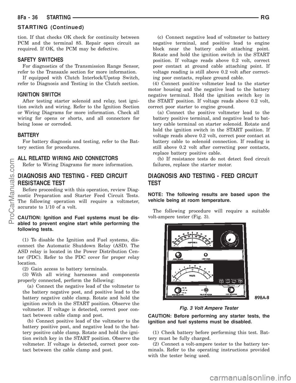
volt-ampere tester (Fig. 3).
CAUTION: Before performing any starter tests, the
ignition and fuel systems must be disabled.
(1) Check battery before performing this test. Bat-
tery must be fully charged.
(2) Connect a volt-ampere tester to the battery ter-
minals. Refer to the operating instructions provided
with the tester being used.
Fig. 3 Volt Ampere Tester
8Fa - 36 STARTINGRG
STARTING (Continued)
ProCarManuals.com
Page 448 of 2399

(3) To disable the ignition and fuel systems, dis-
connect the Automatic Shutdown Relay (ASD). The
ASD relay is located in the Power Distribution Cen-
ter (PDC). Refer to the PDC cover for proper relay
location.
(4) Verify that all lights and accessories are OFF,
and the transmission shift selector is in the PARK
and SET parking brake.
CAUTION: Do not overheat the starter motor or
draw the battery voltage below 9.6 volts during
cranking operations.
(5) Rotate and hold the ignition switch in the
START position. Observe the volt-ampere tester (Fig.
3).
²If voltage reads above 9.6 volts, and amperage
draw reads above 280 amps, check for engine seizing
or faulty starter.
²If voltage reads 12.4 volts or greater and amper-
age reads 0 to 10 amps, check for corroded cables
and/or bad connections.
²Voltage below 9.6 volts and amperage draw
above 300 amps, the problem is the starter. Replace
the starter refer to starter removal.
(6) After the starting system problems have been
corrected, verify the battery state-of-charge and
charge battery if necessary. Disconnect all testing
equipment and connect ASD relay. Start the vehicle
several times to assure the problem has been cor-
rected.SPECIFICATIONS
STARTER
MANUFACTURER NIPPONDENSO
Engine Application 2.4L /3.3/3.8L
Power rating 1.2 Kw
Voltage 12 VOLTS
No. of Fields 4
No. of Poles 4
Brushes 4
Drive Conventional Gear Train
Free running Test
Voltage 11
Amperage Draw 73 Amp
Minimum Speed 3401 RPM
SolenoidClosing Voltage 7.5 Volts
Cranking Amperage Draw
test150 - 200 Amps.
Engine should be up to operating temperature.
Extremely heavy oil or tight engine will increase
starter amperage draw.
Torques
DESCRIPTION N´m Ft. Lbs. In. Lbs.
Starter Mounting Bolts 47.4 35
Starter Solenoid Battery Nut 11.3 8.3 100
RGSTARTING8Fa-37
STARTING (Continued)
ProCarManuals.com
Page 449 of 2399
STARTER MOTOR
REMOVAL
REMOVAL - 2.4L
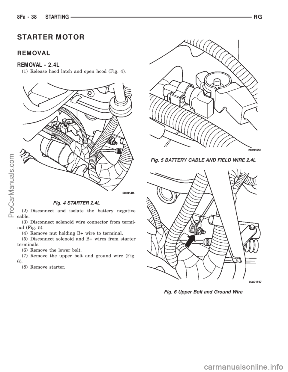
(1) Release hood latch and open hood (Fig. 4).
(2) Disconnect and isolate the battery negative
cable.
(3) Disconnect solenoid wire connector from termi-
nal (Fig. 5).
(4) Remove nut holding B+ wire to terminal.
(5) Disconnect solenoid and B+ wires from starter
terminals.
(6) Remove the lower bolt.
(7) Remove the upper bolt and ground wire (Fig.
6).
(8) Remove starter.
Fig. 4 STARTER 2.4L
Fig. 5 BATTERY CABLE AND FIELD WIRE 2.4L
Fig. 6 Upper Bolt and Ground Wire
8Fa - 38 STARTINGRG
ProCarManuals.com
Page 450 of 2399
REMOVAL - 3.3/3.8L
(1) Release hood latch and open hood.
(2) Disconnect and isolate the battery negative
cable.
(3) Hoist and support vehicle on safety stands.
(4) Remove nut holding B+ terminal to starter
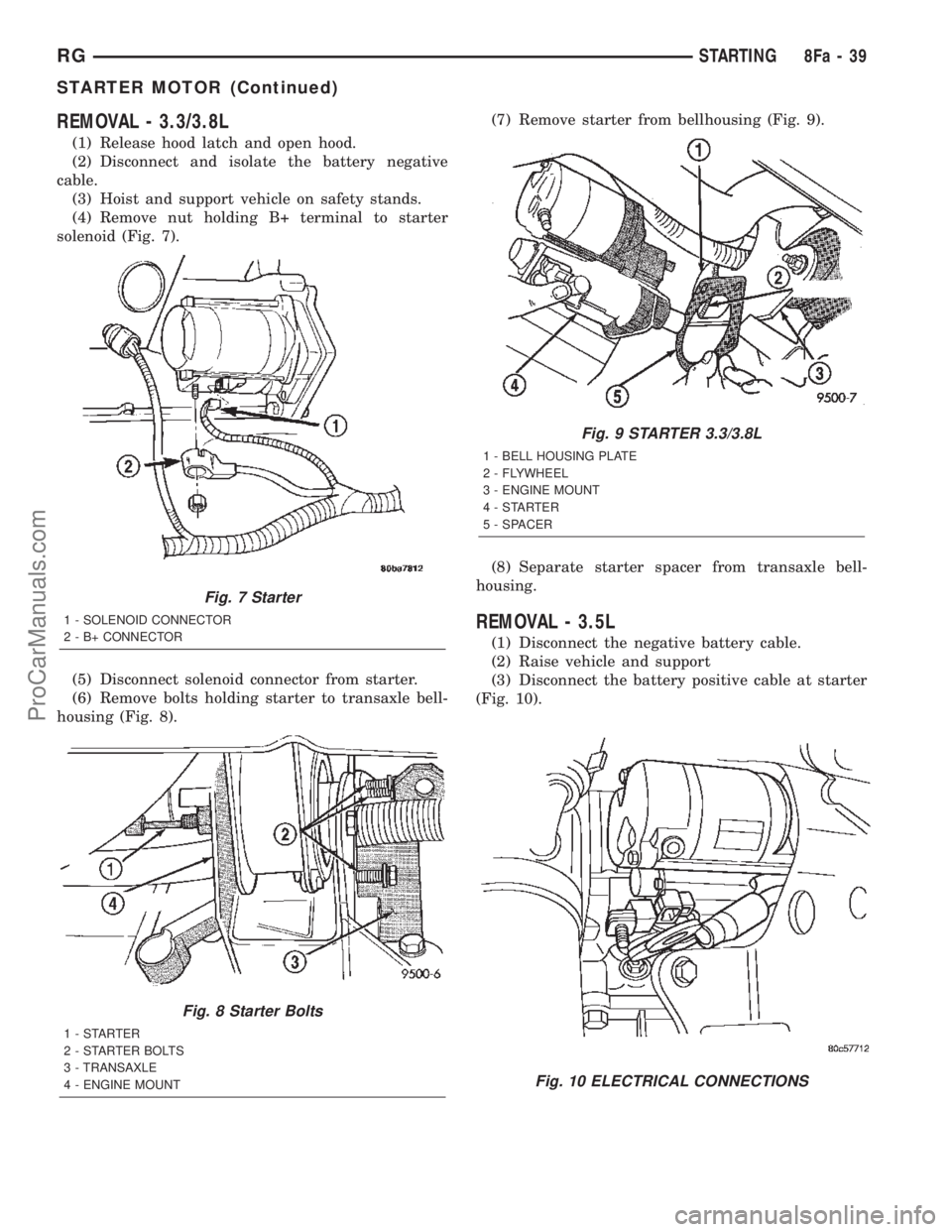
solenoid (Fig. 7).
(5) Disconnect solenoid connector from starter.
(6) Remove bolts holding starter to transaxle bell-
housing (Fig. 8).(7) Remove starter from bellhousing (Fig. 9).
(8) Separate starter spacer from transaxle bell-
housing.
REMOVAL - 3.5L
(1) Disconnect the negative battery cable.
(2) Raise vehicle and support
(3) Disconnect the battery positive cable at starter
(Fig. 10).
Fig. 7 Starter
1 - SOLENOID CONNECTOR
2 - B+ CONNECTOR
Fig. 8 Starter Bolts
1-STARTER
2 - STARTER BOLTS
3 - TRANSAXLE
4 - ENGINE MOUNT
Fig. 9 STARTER 3.3/3.8L
1 - BELL HOUSING PLATE
2 - FLYWHEEL
3 - ENGINE MOUNT
4-STARTER
5 - SPACER
Fig. 10 ELECTRICAL CONNECTIONS
RGSTARTING8Fa-39
STARTER MOTOR (Continued)
ProCarManuals.com
Page 451 of 2399
(4) Disconnect the solenoid connector (Fig. 10).
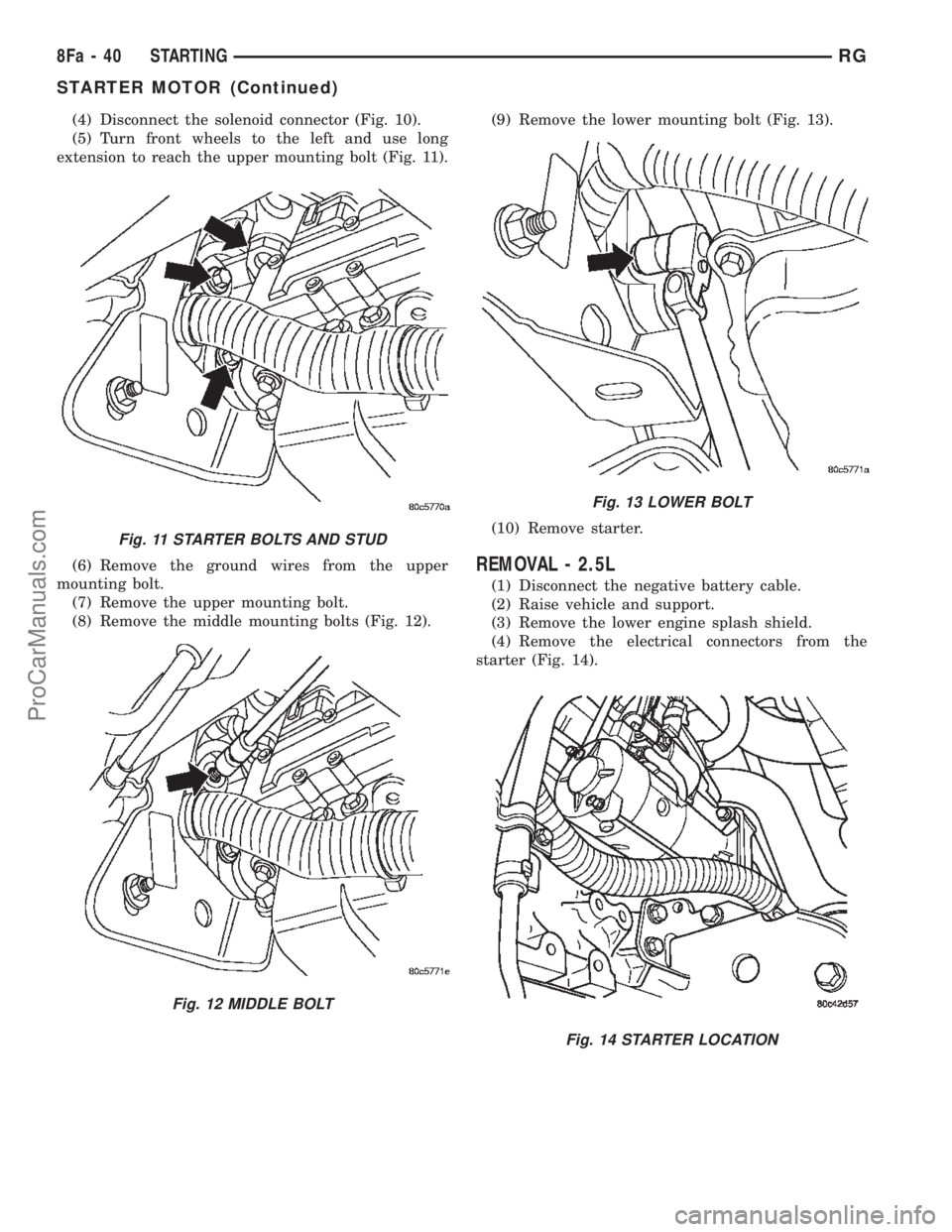
(5) Turn front wheels to the left and use long
extension to reach the upper mounting bolt (Fig. 11).
(6) Remove the ground wires from the upper
mounting bolt.
(7) Remove the upper mounting bolt.
(8) Remove the middle mounting bolts (Fig. 12).(9) Remove the lower mounting bolt (Fig. 13).
(10) Remove starter.
REMOVAL - 2.5L
(1) Disconnect the negative battery cable.
(2) Raise vehicle and support.
(3) Remove the lower engine splash shield.
(4) Remove the electrical connectors from the
starter (Fig. 14).
Fig. 11 STARTER BOLTS AND STUD
Fig. 12 MIDDLE BOLT
Fig. 13 LOWER BOLT
Fig. 14 STARTER LOCATION
8Fa - 40 STARTINGRG
STARTER MOTOR (Continued)
ProCarManuals.com
Page 452 of 2399
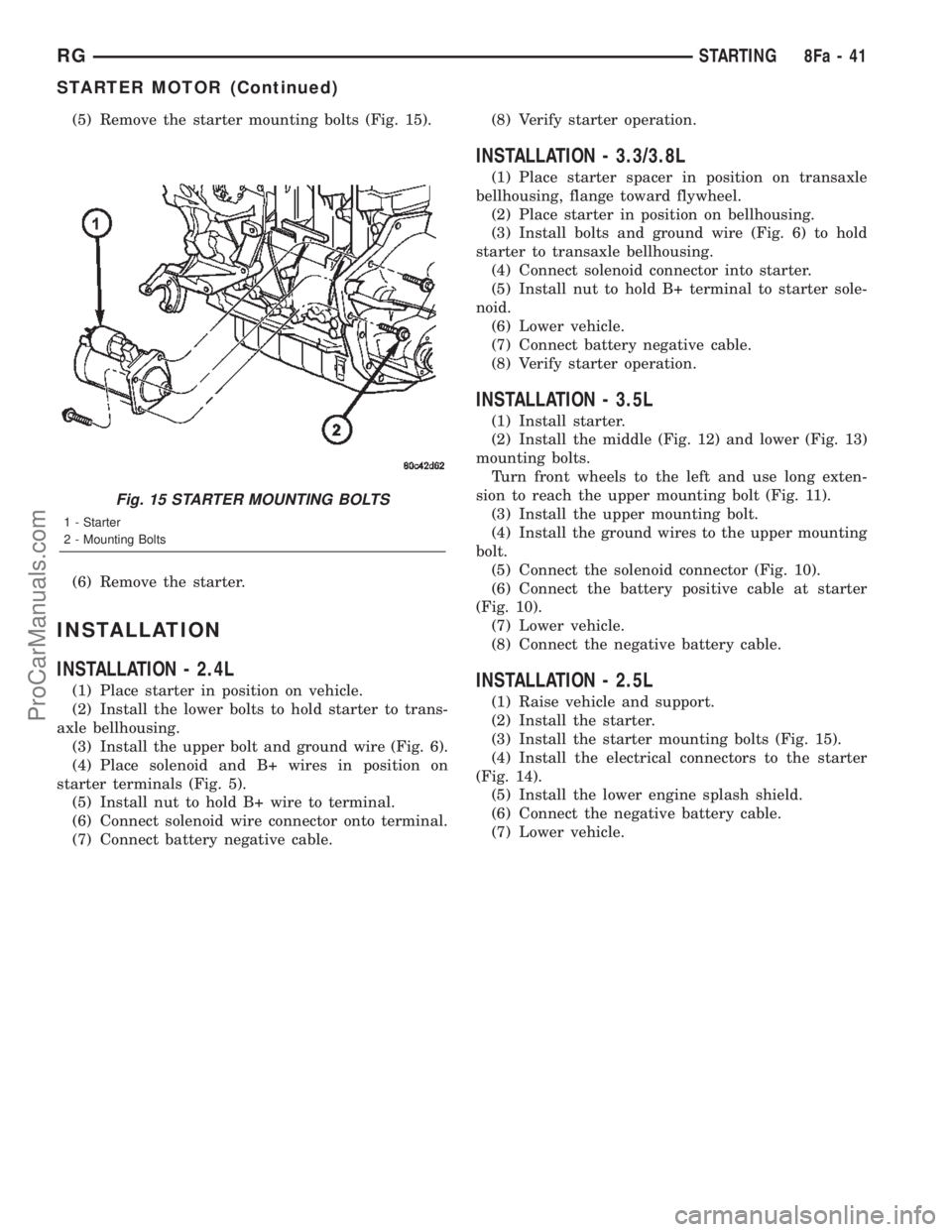
(5) Remove the starter mounting bolts (Fig. 15).
(6) Remove the starter.
INSTALLATION
INSTALLATION - 2.4L
(1) Place starter in position on vehicle.
(2) Install the lower bolts to hold starter to trans-
axle bellhousing.
(3) Install the upper bolt and ground wire (Fig. 6).
(4) Place solenoid and B+ wires in position on
starter terminals (Fig. 5).
(5) Install nut to hold B+ wire to terminal.
(6) Connect solenoid wire connector onto terminal.
(7) Connect battery negative cable.(8) Verify starter operation.
INSTALLATION - 3.3/3.8L
(1) Place starter spacer in position on transaxle
bellhousing, flange toward flywheel.
(2) Place starter in position on bellhousing.
(3) Install bolts and ground wire (Fig. 6) to hold
starter to transaxle bellhousing.
(4) Connect solenoid connector into starter.
(5) Install nut to hold B+ terminal to starter sole-
noid.
(6) Lower vehicle.
(7) Connect battery negative cable.
(8) Verify starter operation.
INSTALLATION - 3.5L
(1) Install starter.
(2) Install the middle (Fig. 12) and lower (Fig. 13)
mounting bolts.
Turn front wheels to the left and use long exten-
sion to reach the upper mounting bolt (Fig. 11).
(3) Install the upper mounting bolt.
(4) Install the ground wires to the upper mounting
bolt.
(5) Connect the solenoid connector (Fig. 10).
(6) Connect the battery positive cable at starter
(Fig. 10).
(7) Lower vehicle.
(8) Connect the negative battery cable.
INSTALLATION - 2.5L
(1) Raise vehicle and support.
(2) Install the starter.
(3) Install the starter mounting bolts (Fig. 15).
(4) Install the electrical connectors to the starter
(Fig. 14).
(5) Install the lower engine splash shield.
(6) Connect the negative battery cable.
(7) Lower vehicle.
Fig. 15 STARTER MOUNTING BOLTS
1 - Starter
2 - Mounting Bolts
RGSTARTING8Fa-41
STARTER MOTOR (Continued)
ProCarManuals.com
Page 454 of 2399

HEATED SYSTEMS
TABLE OF CONTENTS
page page
HEATED GLASS........................... 1
HEATED MIRRORS......................... 5HEATED SEAT SYSTEM..................... 7
HEATED GLASS
TABLE OF CONTENTS
page page
HEATED GLASS
DESCRIPTION..........................1
OPERATION............................2
DEFOGGER RELAY
DESCRIPTION..........................2
REAR WINDOW DEFOGGER GRID
STANDARD PROCEDURE - GRID LINE
REPAIR REAR.........................2REAR WINDOW DEFOGGER SWITCH
DESCRIPTION..........................2
OPERATION............................2
WINDSHIELD GRID
DIAGNOSIS AND TESTING - SYSTEM TEST . . . 3
STANDARD PROCEDURE - GRID LINE AND
TERMINAL REPAIR.....................3
HEATED GLASS
DESCRIPTION
Fig. 1 REAR WINDOW DEFOGGER (TYPICAL)
1 - REAR DEFOGGER GRID
2 - REAR WINDOW
Fig. 2 (TYPICAL) Heated Windshield Wiper De-icer
1 - DEFROSTER OUTLET
2 - VIN #
3 - HEATED WINDSHIELD GRID
RSHEATED SYSTEMS8G-1
ProCarManuals.com