fig. 78 CHRYSLER CARAVAN 2002 Service Manual
[x] Cancel search | Manufacturer: CHRYSLER, Model Year: 2002, Model line: CARAVAN, Model: CHRYSLER CARAVAN 2002Pages: 2399, PDF Size: 57.96 MB
Page 484 of 2399
(3) On All Wheel Drive vehicles install the PTU
(Power Transfer Unit) for the rear wheels, refer to
the Transmission section for more information.
(4) Lower vehicle.
(5) Connect the negative cable.
SPARK PLUG
DESCRIPTION
DESCRIPTION - STANDARD 4 CYLINDER
All engines use resistor spark plugs. They have
resistance values ranging from 6,000 to 20,000 ohms
when checked with at least a 1000 volt spark plug
tester.
Do not use an ohm meter to check the resis-
tance of the spark plugs. This will give an inac-
curate reading.
Refer to the Specifications section for gap and type
of spark plug.
DESCRIPTION - PLATINUM PLUGS
The V6 engines use platinum resistor spark plugs.
They have resistance values of 6,000 to 20,000 ohms
when checked with at least a 1000 volt tester. Forspark plug identification and specifications, Refer to
the Specifications section.
Do not use an ohm meter to check the resis-
tance of the spark plugs. This will give an inac-
curate reading.
When the spark plugs use a single or double plat-
inum tips and they have a recommended service life
of 100,000 miles for normal driving conditions per
schedule A in this manual. The spark plugs have a
recommended service life of 75,000 miles for severe
driving conditions per schedule B in this manual. A
thin platinum pad is welded to both or center elec-
trode end(s) as show in (Fig. 13). Extreme care must
be used to prevent spark plug cross threading, mis-
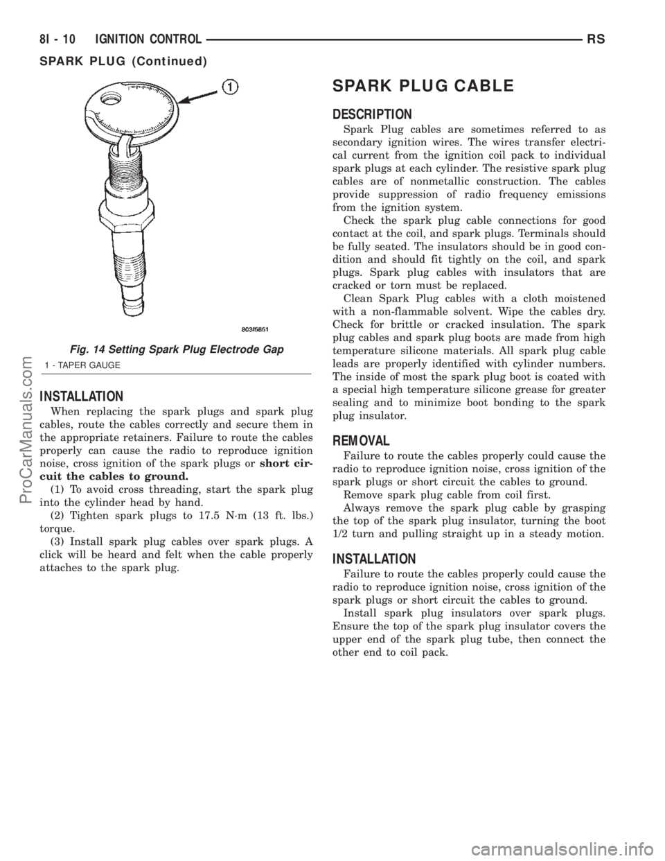
gaping (Fig. 14) and ceramic insulator damage dur-
ing plug removal and installation.
CAUTION: Cleaning of the platinum plug may dam-
age the platinum tip.
REMOVAL
When replacing the spark plugs and spark plug
cables, route the cables correctly and secure them in
the appropriate retainers. Failure to route the cables
properly can cause the radio to reproduce ignition
noise, cross ignition of the spark plugs orshort cir-
cuit the cables to ground.
Always remove cables by grasping at the boot,
rotating the boot 1/2 turn, and pulling straight back
in a steady motion.
(1) Prior to removing the spark plug, spray com-
pressed air around the spark plug hole and the area
around the spark plug.
(2) Remove the spark plug using a quality socket
with a foam insert.
(3) Inspect the spark plug condition.
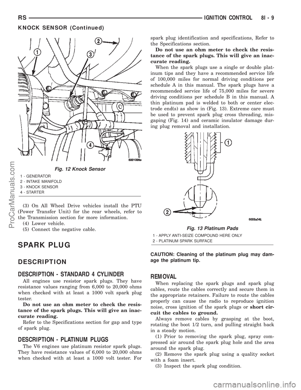
Fig. 12 Knock Sensor
1 - GENERATOR
2 - INTAKE MANIFOLD
3 - KNOCK SENSOR
4-STARTER
Fig. 13 Platinum Pads
1 - APPLY ANTI-SEIZE COMPOUND HERE ONLY
2 - PLATINUM SPARK SURFACE
RSIGNITION CONTROL8I-9
KNOCK SENSOR (Continued)
ProCarManuals.com
Page 485 of 2399
INSTALLATION
When replacing the spark plugs and spark plug
cables, route the cables correctly and secure them in
the appropriate retainers. Failure to route the cables
properly can cause the radio to reproduce ignition
noise, cross ignition of the spark plugs orshort cir-
cuit the cables to ground.
(1) To avoid cross threading, start the spark plug
into the cylinder head by hand.
(2) Tighten spark plugs to 17.5 N´m (13 ft. lbs.)
torque.
(3) Install spark plug cables over spark plugs. A
click will be heard and felt when the cable properly
attaches to the spark plug.
SPARK PLUG CABLE
DESCRIPTION
Spark Plug cables are sometimes referred to as
secondary ignition wires. The wires transfer electri-
cal current from the ignition coil pack to individual
spark plugs at each cylinder. The resistive spark plug
cables are of nonmetallic construction. The cables
provide suppression of radio frequency emissions
from the ignition system.
Check the spark plug cable connections for good
contact at the coil, and spark plugs. Terminals should
be fully seated. The insulators should be in good con-
dition and should fit tightly on the coil, and spark
plugs. Spark plug cables with insulators that are
cracked or torn must be replaced.
Clean Spark Plug cables with a cloth moistened
with a non-flammable solvent. Wipe the cables dry.
Check for brittle or cracked insulation. The spark
plug cables and spark plug boots are made from high
temperature silicone materials. All spark plug cable
leads are properly identified with cylinder numbers.
The inside of most the spark plug boot is coated with
a special high temperature silicone grease for greater
sealing and to minimize boot bonding to the spark
plug insulator.
REMOVAL
Failure to route the cables properly could cause the
radio to reproduce ignition noise, cross ignition of the
spark plugs or short circuit the cables to ground.
Remove spark plug cable from coil first.
Always remove the spark plug cable by grasping
the top of the spark plug insulator, turning the boot
1/2 turn and pulling straight up in a steady motion.
INSTALLATION
Failure to route the cables properly could cause the
radio to reproduce ignition noise, cross ignition of the
spark plugs or short circuit the cables to ground.
Install spark plug insulators over spark plugs.
Ensure the top of the spark plug insulator covers the
upper end of the spark plug tube, then connect the
other end to coil pack.
Fig. 14 Setting Spark Plug Electrode Gap
1 - TAPER GAUGE
8I - 10 IGNITION CONTROLRS
SPARK PLUG (Continued)
ProCarManuals.com
Page 486 of 2399
IGNITION CONTROL
TABLE OF CONTENTS
page page
GLOW PLUG
DESCRIPTION..........................1
OPERATION............................1
GLOW PLUG RELAY
DESCRIPTION..........................1
OPERATION............................1CAMSHAFT POSITION SENSOR
DESCRIPTION..........................2
OPERATION............................2
REMOVAL.............................2
INSTALLATION..........................2
GLOW PLUG
DESCRIPTION
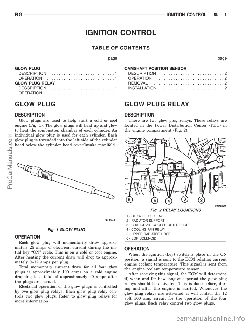
Glow plugs are used to help start a cold or cool
engine (Fig. 1). The glow plugs will heat up and glow
to heat the combustion chamber of each cylinder. An
individual glow plug is used for each cylinder. Each
glow plug is threaded into the left side of the cylinder
head below the cylinder head cover/intake manifold.
OPERATION
Each glow plug will momentarily draw approxi-
mately 25 amps of electrical current during the ini-
tial key ªONº cycle. This is on a cold or cool engine.
After heating the current draw will drop to approxi-
mately 9±12 amps per plug.
Total momentary cuurent draw for all four glow
plugs is approximately 100 amps on a cold engine
dropping to a total of approximately 40 amps after
the plugs are heated.
Electrical operation of the glow plugs is controlled
by two glow plug relays. Each glow plug relay con-
trols two glow plugs. Refer to glow plug relays for
more information.
GLOW PLUG RELAY
DESCRIPTION
There are two glow plug relays. These relays are
located in the Power Distribution Center (PDC) in
the engine compartment (Fig. 2).
OPERATION
When the ignition (key) switch is place in the ON
position, a signal is sent to the ECM relating current
engine coolant temperature. This signal is sent from
the engine coolant temperature sensor.
After receiving this signal, the ECM will determine
if, when and for how long of a period the glow plug
relays should be activated. This is done before, dur-
ing and after the engine is started. Whenever the
glow plug relays are activated, it will control the 12
volt 100 amp circuit for the operation of the four
glow plugs. Each relay control two glow plugs.
Fig. 1 GLOW PLUG
Fig. 2 RELAY LOCATIONS
1 - GLOW PLUG RELAY
2 - RADIATOR SUPPORT
3 - CHARGE AIR COOLER OUTLET HOSE
4 - COOLING FAN RELAY
5 - UPPER RADIATOR HOSE
6 - EGR SOLENOID
RGIGNITION CONTROL8Ia-1
ProCarManuals.com
Page 487 of 2399
The Glow Plug lamp is tied to this circuit. Lamp
operation is also controlled by the ECM.
With a cold engine, the glow plug relays and glow
plugs may be activated for a maximum time of 200
seconds. Refer to the following Glow Plug Control
chart for a temperature/time comparison of the glow
plug relay operation.
In this chart, Pre-Heat and Post-Heat times are
mentioned. Pre-Heat is the amount of time the glow
plug relay control circuit is activated when the igni-
tion (key) is switched ON, without the engine run-
ning. Post-Heat is the amount of time the glow plug
relay control circuit is activated after the engine is
operated. The Glow Plug lamp will not be activated
during the post-heat cycle.
Engine
Coolant
Temperature
9Key ON9Wait-To
Start Lamp
9ON9
(Seconds)Pre-Heat
Cycle
(Glow
Plugs On
Seconds)Post-Heat
Cycle
(Seconds)
-30C 20 SEC. 35 SEC. 200 SEC.
-10C 8 SEC. 23 SEC. 180 SEC.
+10C 6 SEC. 21 SEC. 160 SEC.
+30C 5 SEC. 20 SEC. 140 SEC.
+40C 4 SEC. 19 SEC. 70 SEC.
+70C 1 SEC. 16 SEC. 20 SEC.
CAMSHAFT POSITION
SENSOR
DESCRIPTION
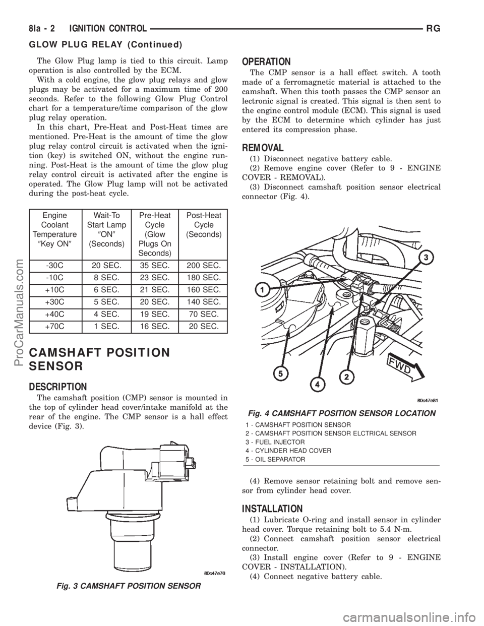
The camshaft position (CMP) sensor is mounted in
the top of cylinder head cover/intake manifold at the
rear of the engine. The CMP sensor is a hall effect
device (Fig. 3).
OPERATION
The CMP sensor is a hall effect switch. A tooth
made of a ferromagnetic material is attached to the
camshaft. When this tooth passes the CMP sensor an
lectronic signal is created. This signal is then sent to
the engine control module (ECM). This signal is used
by the ECM to determine which cylinder has just
entered its compression phase.
REMOVAL
(1) Disconnect negative battery cable.
(2) Remove engine cover (Refer to 9 - ENGINE
COVER - REMOVAL).
(3) Disconnect camshaft position sensor electrical
connector (Fig. 4).
(4) Remove sensor retaining bolt and remove sen-
sor from cylinder head cover.
INSTALLATION
(1) Lubricate O-ring and install sensor in cylinder
head cover. Torque retaining bolt to 5.4 N´m.
(2) Connect camshaft position sensor electrical
connector.
(3) Install engine cover (Refer to 9 - ENGINE
COVER - INSTALLATION).
(4) Connect negative battery cable.
Fig. 3 CAMSHAFT POSITION SENSOR
Fig. 4 CAMSHAFT POSITION SENSOR LOCATION
1 - CAMSHAFT POSITION SENSOR
2 - CAMSHAFT POSITION SENSOR ELCTRICAL SENSOR
3 - FUEL INJECTOR
4 - CYLINDER HEAD COVER
5 - OIL SEPARATOR
8Ia - 2 IGNITION CONTROLRG
GLOW PLUG RELAY (Continued)
ProCarManuals.com
Page 505 of 2399

SPECIFICATIONS
EXTERIOR LAMPS
BULB APPLICATION TABLE
LAMP BULB
BACK-UP 3057
CHMSL 921
FRONT SIDE MARKER/PARK/
TURN3157A
FOG LAMP 9040
HEADLAMP 9007
LICENSE 168
TAIL, STOP 3057
TURN SIGNAL 3057
BULB APPLICATION TABLE - EXPORT
LAMP BULB
HEADLAMP H7
FRONT POSITION W5W
FRONT TURN SIGNAL PY21W
SIDE REPEATER T4W
LICENSE PLATE W5W/168
REAR TAIL AND STOP P21/5W
REAR TURN SIGNAL PY21W
BACK-UP P21W
REAR FOG P21W
CHMSL W16W/921
BRAKE LAMP SWITCH
DESCRIPTION
The brake lamp switch is located under the instru-
ment panel, at the brake pedal arm (Fig. 3). It has
three internal switches controlling various functions
of the vehicle. It's main function is to control opera-
tion of the vehicle's brake lamps. Other functions
include speed control deactivation, brake sense for
the antilock brake system and brake sense for the
brake transmission shift interlock.
CAUTION: The switch can only be adjusted once.
That is during initial installation of the switch. If the
switch is not adjusted properly or has been
removed for some service, a new switch must be
installed and adjusted.
OPERATION
When the brake pedal is pressed, the plunger on
the outside of the brake lamp switch extends out-
ward. This action opens or closes the contacts of the
three switches inside the brake lamp switch.
With the brake pedal pressed down (plunger
extended), the switch for terminals 1 and 2 is closed
completing the circuit. The switch for terminals 3
and 4 is open and so is the switch for terminals 5
and 6.
When the brake pedal is released (plunger pushed
in), the three switches assume the opposite positions.
The switch for terminals 1 and 2 is now open while
the other two switches are now closed, completing
their circuits.
A lever on the back of the switch is used to set the
switch into the ªadjustedº position. A non-adjusted
switch will have the lever set to the diagonal position
in relation to the switch housing. The plunger can be
moved in and out, but the states of the internal
switches will not change.
CAUTION: Never move the adjustment lever of the
new brake lamp switch without it being properly
installed in the vehicle first. Such action will render
the switch unusable and the switch must be dis-
carded.
Once installed in the vehicle as described in the
brake lamp switch installation procedure (Refer to 8 -
ELECTRICAL/LAMPS/LIGHTING - EXTERIOR/
BRAKE LAMP SWITCH - INSTALLATION), the new
switch's adjustment lever is rotated to the adjusted
position as indicated (Fig. 4). This action locks the
plunger to the internal switches.Once in this posi-
tion the switch is permanently adjusted (or
locked) and cannot be readjusted or released
even if the lever is moved back.
DIAGNOSIS AND TESTING - BRAKE LAMP
SWITCH
NOTE: Before proceeding with this diagnostic test,
verify the adjustment lever on the back of the
switch is in the adjusted position. If the lever is in
the non-adjusted (diagonal) position it may have
never been adjusted (Refer to 8 - ELECTRICAL/
LAMPS/LIGHTING - EXTERIOR/BRAKE LAMP
SWITCH - OPERATION). For adjustment, (Refer to 8
- ELECTRICAL/LAMPS/LIGHTING - EXTERIOR/
BRAKE LAMP SWITCH - INSTALLATION)
If the electrical circuit has been tested and the
brake lamp switch is suspected of being faulty, it can
be tested using the following method.
8L - 4 LAMPS/LIGHTING - EXTERIORRS
LAMPS/LIGHTING - EXTERIOR (Continued)
ProCarManuals.com
Page 506 of 2399
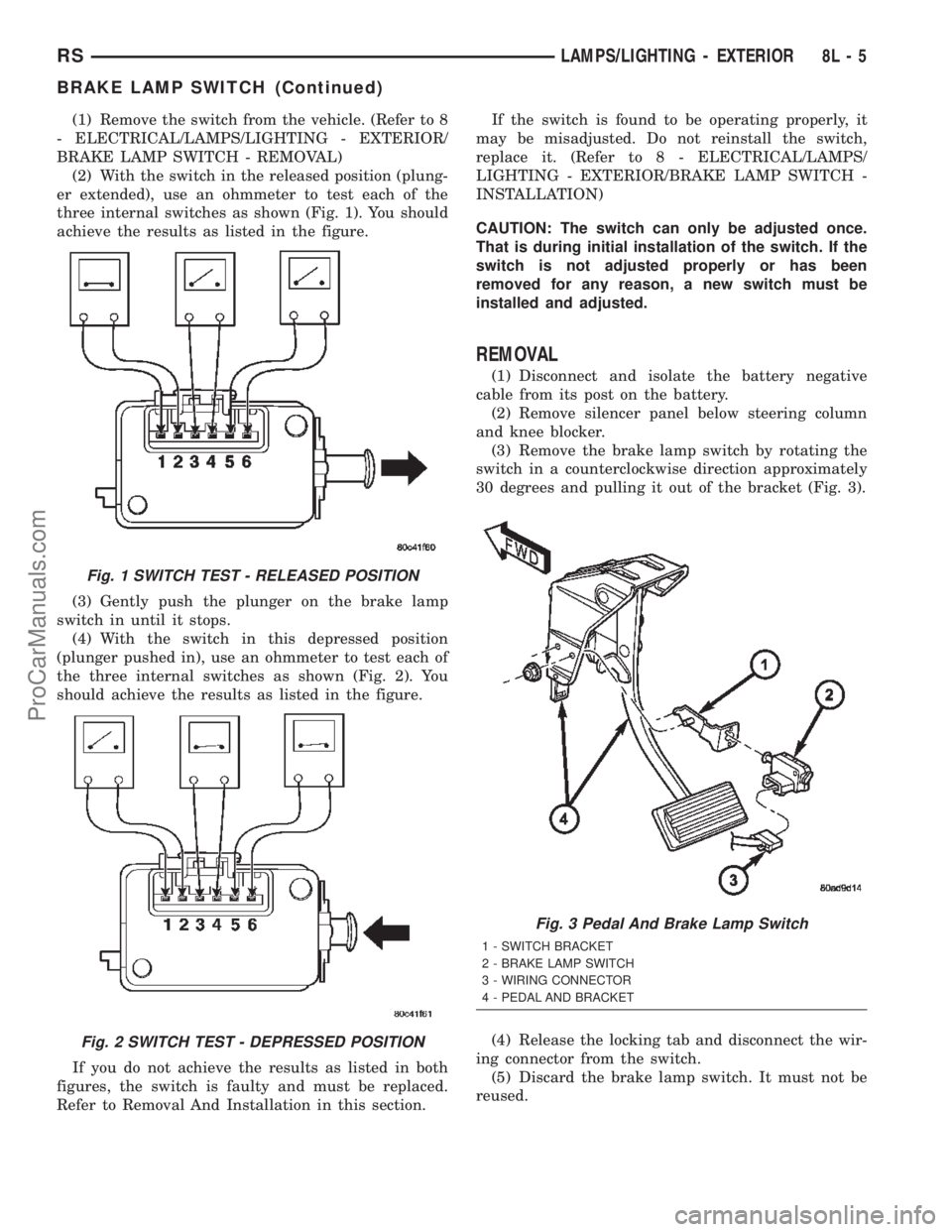
(1) Remove the switch from the vehicle. (Refer to 8
- ELECTRICAL/LAMPS/LIGHTING - EXTERIOR/
BRAKE LAMP SWITCH - REMOVAL)
(2) With the switch in the released position (plung-
er extended), use an ohmmeter to test each of the
three internal switches as shown (Fig. 1). You should
achieve the results as listed in the figure.
(3) Gently push the plunger on the brake lamp
switch in until it stops.
(4) With the switch in this depressed position
(plunger pushed in), use an ohmmeter to test each of
the three internal switches as shown (Fig. 2). You
should achieve the results as listed in the figure.
If you do not achieve the results as listed in both
figures, the switch is faulty and must be replaced.
Refer to Removal And Installation in this section.If the switch is found to be operating properly, it
may be misadjusted. Do not reinstall the switch,
replace it. (Refer to 8 - ELECTRICAL/LAMPS/
LIGHTING - EXTERIOR/BRAKE LAMP SWITCH -
INSTALLATION)
CAUTION: The switch can only be adjusted once.
That is during initial installation of the switch. If the
switch is not adjusted properly or has been
removed for any reason, a new switch must be
installed and adjusted.
REMOVAL
(1) Disconnect and isolate the battery negative
cable from its post on the battery.
(2) Remove silencer panel below steering column
and knee blocker.
(3) Remove the brake lamp switch by rotating the
switch in a counterclockwise direction approximately
30 degrees and pulling it out of the bracket (Fig. 3).
(4) Release the locking tab and disconnect the wir-
ing connector from the switch.
(5) Discard the brake lamp switch. It must not be
reused.
Fig. 1 SWITCH TEST - RELEASED POSITION
Fig. 2 SWITCH TEST - DEPRESSED POSITION
Fig. 3 Pedal And Brake Lamp Switch
1 - SWITCH BRACKET
2 - BRAKE LAMP SWITCH
3 - WIRING CONNECTOR
4 - PEDAL AND BRACKET
RSLAMPS/LIGHTING - EXTERIOR8L-5
BRAKE LAMP SWITCH (Continued)
ProCarManuals.com
Page 507 of 2399
INSTALLATION
CAUTION: Do not reuse the original brake lamp
switch. The switch can only be adjusted once. That
is during initial installation of the switch. If the
switch is not adjusted properly or has been
removed for some service, a new switch must be
installed and adjusted.
(1) Mount and adjust the NEW brake lamp switch
using the following procedure:
(a) Connect the wiring connector to the switch
and latch the locking tab.
(b) Install the switch in its bracket by aligning
the index tab on the switch with the slot in the
mounting bracket.
(c) When the switch is fully seated in its
bracket, rotate the switch clockwise approximately
30É to lock the switch into place (Fig. 3).
(d) With the brake pedal in the fully released
position, move the lever on the back of the brake
lamp switch from the angled non-adjusted position
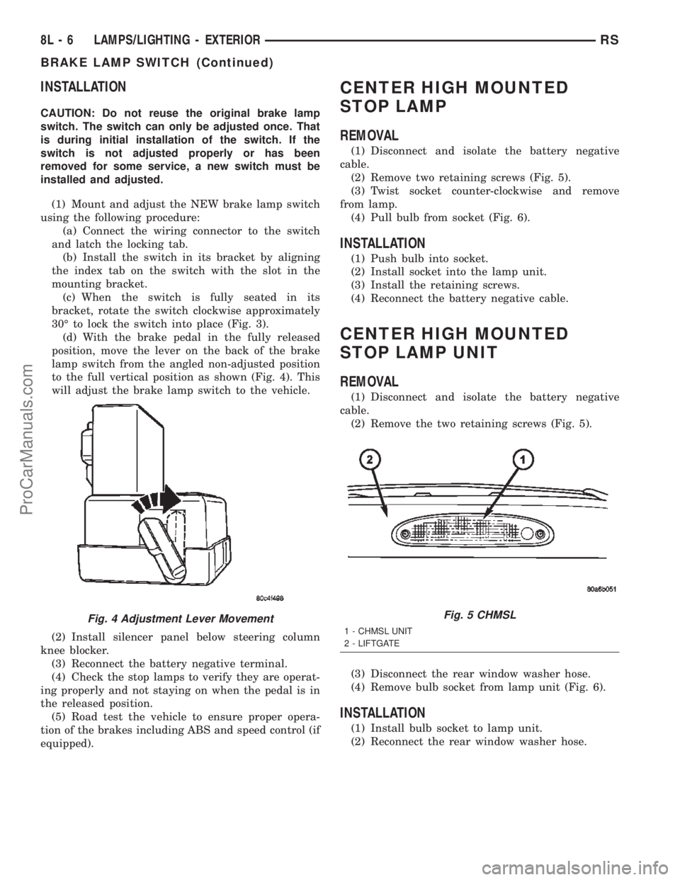
to the full vertical position as shown (Fig. 4). This
will adjust the brake lamp switch to the vehicle.
(2) Install silencer panel below steering column
knee blocker.
(3) Reconnect the battery negative terminal.
(4) Check the stop lamps to verify they are operat-
ing properly and not staying on when the pedal is in
the released position.
(5) Road test the vehicle to ensure proper opera-
tion of the brakes including ABS and speed control (if
equipped).
CENTER HIGH MOUNTED
STOP LAMP
REMOVAL
(1) Disconnect and isolate the battery negative
cable.
(2) Remove two retaining screws (Fig. 5).
(3) Twist socket counter-clockwise and remove
from lamp.
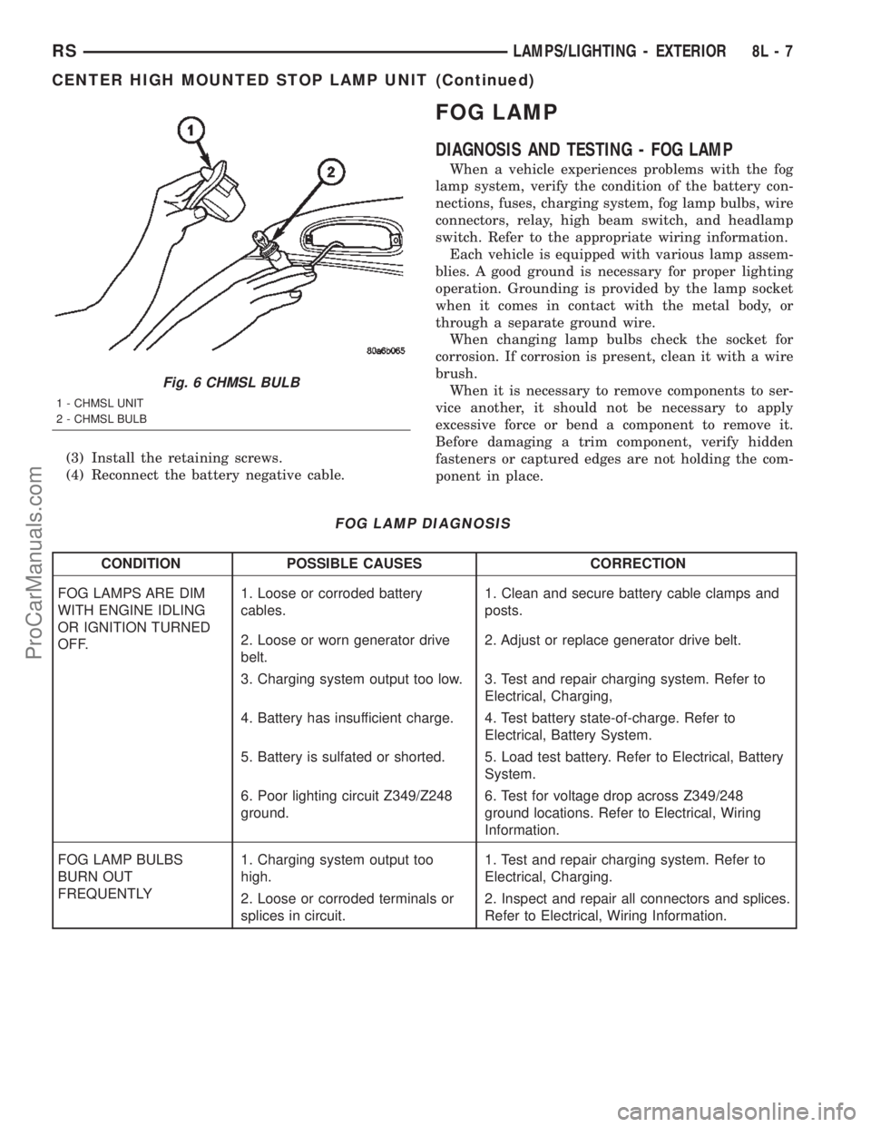
(4) Pull bulb from socket (Fig. 6).
INSTALLATION
(1) Push bulb into socket.
(2) Install socket into the lamp unit.
(3) Install the retaining screws.
(4) Reconnect the battery negative cable.
CENTER HIGH MOUNTED
STOP LAMP UNIT
REMOVAL
(1) Disconnect and isolate the battery negative
cable.
(2) Remove the two retaining screws (Fig. 5).
(3) Disconnect the rear window washer hose.
(4) Remove bulb socket from lamp unit (Fig. 6).
INSTALLATION
(1) Install bulb socket to lamp unit.
(2) Reconnect the rear window washer hose.
Fig. 4 Adjustment Lever MovementFig. 5 CHMSL
1 - CHMSL UNIT
2 - LIFTGATE
8L - 6 LAMPS/LIGHTING - EXTERIORRS
BRAKE LAMP SWITCH (Continued)
ProCarManuals.com
Page 508 of 2399
(3) Install the retaining screws.
(4) Reconnect the battery negative cable.
FOG LAMP
DIAGNOSIS AND TESTING - FOG LAMP
When a vehicle experiences problems with the fog
lamp system, verify the condition of the battery con-
nections, fuses, charging system, fog lamp bulbs, wire
connectors, relay, high beam switch, and headlamp
switch. Refer to the appropriate wiring information.
Each vehicle is equipped with various lamp assem-
blies. A good ground is necessary for proper lighting
operation. Grounding is provided by the lamp socket
when it comes in contact with the metal body, or
through a separate ground wire.
When changing lamp bulbs check the socket for
corrosion. If corrosion is present, clean it with a wire
brush.
When it is necessary to remove components to ser-
vice another, it should not be necessary to apply
excessive force or bend a component to remove it.
Before damaging a trim component, verify hidden
fasteners or captured edges are not holding the com-
ponent in place.
FOG LAMP DIAGNOSIS
CONDITION POSSIBLE CAUSES CORRECTION
FOG LAMPS ARE DIM
WITH ENGINE IDLING
OR IGNITION TURNED
OFF.1. Loose or corroded battery
cables.1. Clean and secure battery cable clamps and
posts.
2. Loose or worn generator drive
belt.2. Adjust or replace generator drive belt.
3. Charging system output too low. 3. Test and repair charging system. Refer to
Electrical, Charging,
4. Battery has insufficient charge. 4. Test battery state-of-charge. Refer to
Electrical, Battery System.
5. Battery is sulfated or shorted. 5. Load test battery. Refer to Electrical, Battery
System.
6. Poor lighting circuit Z349/Z248
ground.6. Test for voltage drop across Z349/248
ground locations. Refer to Electrical, Wiring
Information.
FOG LAMP BULBS
BURN OUT
FREQUENTLY1. Charging system output too
high.1. Test and repair charging system. Refer to
Electrical, Charging.
2. Loose or corroded terminals or
splices in circuit.2. Inspect and repair all connectors and splices.
Refer to Electrical, Wiring Information.
Fig. 6 CHMSL BULB
1 - CHMSL UNIT
2 - CHMSL BULB
RSLAMPS/LIGHTING - EXTERIOR8L-7
CENTER HIGH MOUNTED STOP LAMP UNIT (Continued)
ProCarManuals.com
Page 510 of 2399

REMOVAL
(1) Disconnect and isolate the battery negative
cable.
(2) From behind the bumper fascia, twist bulb
counter-clockwise, and remove bulb. (Fig. 7).
(3) Remove the wire connector from the fog lamp
bulb.
INSTALLATION
(1) Reconnect wire harness to bulb.
(2) Install bulb and twist clockwise.
(3) Install battery negative cable.
FOG LAMP - EXPORT
REMOVAL
(1) Disconnect and isolate the battery negative
cable.
(2) Remove access cover from under bumper fascia.
(3) Disengage spring clip from fog lamp (Fig. 8).
(4) Remove bulb from lamp.
(5) Disconnect wire harness connector.
INSTALLATION
(1) Connect wire harness connector.
(2) Install bulb to lamp.
(3) Engage spring clip to fog lamp.
(4) Install access cover under bumper fascia.
(5) Connect battery negative cable.
Fig. 7 FOG LAMP
1 - FOGLAMP MOUNTING NUT
2 - FOGLAMP
Fig. 8 FOG LAMP
1 - SPRING CLIP
2 - FOG LAMP
RSLAMPS/LIGHTING - EXTERIOR8L-9
FOG LAMP (Continued)
ProCarManuals.com
Page 511 of 2399

FOG LAMP UNIT
STANDARD PROCEDURE
STANDARD PROCEDURE - FOG LAMP UNIT
ALIGNMENT
FOG LAMP UNIT ALIGNMENT
Prepare an alignment screen (Refer to 8 - ELEC-
TRICAL/LAMPS/LIGHTING - EXTERIOR/HEAD-
LAMP UNIT - STANDARD PROCEDURE). A
properly aligned fog lamp will project a pattern on
the alignment screen 100 mm (4 in.) below the fog
lamp center line and straight ahead (Fig. 9). To
improve visual interpretation of the fog lamp patternon the alignment screen, the headlamps should be in
the ªoffº position.
The fog lamps are adjusted by a adjustment screw
located through the lens on Dodge vehicles, and by a
knob on the back of the lamp.
STANDARD PROCEDURE - FOG LAMP UNIT
ALIGNMENT - EXPORT
Prepare an alignment screen (Refer to 8 - ELEC-
TRICAL/LAMPS/LIGHTING - EXTERIOR/HEAD-
LAMP UNIT - STANDARD PROCEDURE). A
properly aligned fog lamp will project a pattern on
the alignment screen 200 mm (8 in.) below the fog
lamp center line and straight ahead (Fig. 10). To
improve visual interpretation of the fog lamp pattern
on the alignment screen, the headlamps should be in
the ªoffº position.
Fig. 9 FOG LAMP UNIT ALIGNMENT
1 - HIGH INTENSITY AREA 4 - 100MM (4 IN.)
2 - CENTER OF VEHICLE 5 - 7.62 METERS (25 FT.)
3 - HORIZONTAL CENTER OF FOG LAMP 6 - FRONT OF FOG LAMP
8L - 10 LAMPS/LIGHTING - EXTERIORRS
ProCarManuals.com