clock CHRYSLER CARAVAN 2003 Repair Manual
[x] Cancel search | Manufacturer: CHRYSLER, Model Year: 2003, Model line: CARAVAN, Model: CHRYSLER CARAVAN 2003Pages: 2177, PDF Size: 59.81 MB
Page 1118 of 2177

CONNECTOR NAME/NUMBER COLOR LOCATION FIG.
C317 BK Right Sliding Door 31
C318 (Trailer Tow) BK Left Quarter N/S
C319 Left Side Liftgate N/S
C320 DKGY Driver Power Seat on Seat Harness N/S
C321 DKGY Under Passenger Seat N/S
C322 BK On Seat Harness to Body 31
C324 BK Left Sliding Door N/S
C325 BK Right Sliding Door 31
C326 YL At Driver Side Airbag N/S
C327 YL At Passenger Side Airbag N/S
C328 Front of Left Quarter 46
C329 (Diesel) BK Near Fuel Tank 33
C330 (Diesel) LTGY Left Rear Engine Compartment N/S
C331 (Diesel) BK Left Rear Engine Compartment N/S
Cabin Heater RHD) At Heater N/S
Cabin Heater Assist C1 (Diesel) BK Top of Engine 15, 16
Cabin Heater Assist C2 (Diesel) BK Top of Engine 15, 16
Camshaft Position Sensor (Gas) BK Rear of Cylinder Head
Right Side of Engine11
Camshaft Position Sensor
(Diesel)BK Rear of Cylinder Head 15, 16
CD Changer Behind CD Changer N/S
Center Dome Lamp GY At Lamp N/S
Center High Mounted Stop Lamp BK At Lamp 48
Clockspring - C1 WT Steering Column 19, 20, 21, 22, 30
Clockspring - C2 YL Steering Column 19, 20, 21, 22, 30
Clockspring - C3 BK Steering Column N/S
Clockspring - C4 BK Steering Column N/S
Clockspring - C5 YL Steering Column N/S
Clutch Pedal Interlock Switch
(Diesel)RD At Switch/Driver Side 41
Clutch Pedal Upstop Switch
(Diesel)BK At Switch/Driver Side 41
Controller Anti-Lock Brake BK Right Side of Engine Compartment 11, 16, 17, 18
Crank Case Ventilation Heater
(Diesel)BK Top of Cylinder Head 15
Crankshaft Position Sensor
(Diesel)BK Rear of Engine 16
Crankshaft Position Sensor (Gas) BK Rear of Engine 13, 17
Data Link Connector WT Lower Instrument Panel Near
Steering Column40, 41
Dosing Pump BK Top of Engine N/S
Driver Airbag Squib1 BN Steering Column N/S
Driver Airbag Squib2 BK Steering Column N/S
RS8W-91 CONNECTOR/GROUND/SPLICE LOCATION8W-91-3
CONNECTOR/GROUND/SPLICE LOCATION (Continued)
ProCarManuals.com
Page 1176 of 2177
to the fused B(+) fuse in the IPM that feeds the
accessories when the relay is energized by the igni-
tion switch. There should be continuity between the
IPM cavity for relay terminal 87 and the fused B(+)
fuse in the IPM at all times. If OK, go to Step 4. If
not OK, repair the open fused B(+) circuit to the IPM
fuse as required.
(4) The coil ground terminal (85) is connected to
the electromagnet in the relay. It receives battery
feed to energize the accessory relay when the ignition
switch is in the Accessory or On positions. Turn the
ignition switch to the On position. Check for battery
voltage at the fused ignition switch output (acc/run)
circuit cavity for relay terminal 85 in the IPM recep-
tacle for the accessory relay. If OK, go to Step 5. If
not OK, repair the open fused ignition switch output
(acc/run) circuit to the ignition switch as required.
(5) The coil battery terminal (86) is connected to
the electromagnet in the relay. The IPM cavity for
this terminal should have continuity to ground at all
times. If not OK, repair the open ground circuit to
ground as required.
REMOVAL
(1) Disconnect and isolate the battery negative
cable.
(2) Remove the Integrated Power Module (IPM)
cover from the IPM.
(3) Remove the accessory relay from the IPM.
Refer to the IPM cover for relay location.
INSTALLATION
(1) Position the accessory relay in the proper
receptacle in the Integrated Power Module (IPM).
(2) Push in firmly on the accessory relay until the
terminals are fully seated in the terminal cavities in
the IPM receptacle.
(3) Install the IPM cover.
(4) Reconnect the battery negative cable.
INTEGRATED POWER MODULE
DESCRIPTION
The Integrated Power Module (IPM) is a combina-
tion of the Power Distribution Center (PDC) and the
Front Control Module (FCM). The IPM is located in
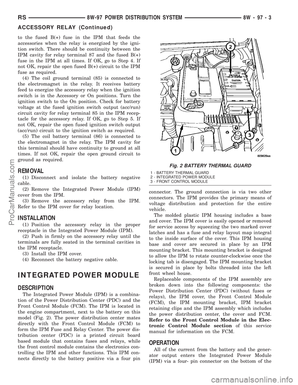
the engine compartment, next to the battery on this
model (Fig. 2). The power distribution center mates
directly with the Front Control Module (FCM) to
form the IPM Fuse and Relay Center. The power dis-
tribution center (PDC) is a printed circuit board
based module that contains fuses and relays, while
the front control module contains the electronics con-
trolling the IPM and other functions. This IPM con-
nects directly to the battery positive via a four pinconnector. The ground connection is via two other
connectors. The IPM provides the primary means of
voltage distribution and protection for the entire
vehicle.
The molded plastic IPM housing includes a base
and cover. The IPM cover is easily opened or removed
for service access by squeezing the two marked cover
latches and has a fuse and relay layout map integral
to the inside surface of the cover. This IPM housing
base and cover are secured in place by an IPM
mounting bracket. This mounting bracket is designed
to allow the IPM to rotate counter-clockwise once the
locking tab is disengaged. The IPM mounting bracket
is secured in place by bolts threaded into the left
front wheel house.
Replaceable components of the IPM assembly are
broken down into the following components: the
Power Distribution Center (PDC) (without fuses or
relays), the IPM cover, the Front Control Module
(FCM), the IPM mounting bracket, IPM bracket
retaining clips and the IPM assembly which includes
the power distribution center, the cover and FCM.
Refer to the Front Control Module in the Elec-
tronic Control Module sectionof this service
manual for information on the FCM.
OPERATION
All of the current from the battery and the gener-
ator output enters the Integrated Power Module
(IPM) via a four- pin connector on the bottom of the
Fig. 2 BATTERY THERMAL GUARD
1 - BATTERY THERMAL GUARD
2 - INTEGRATED POWER MODULE
3 - FRONT CONTROL MODULE
RS8W-97 POWER DISTRIBUTION SYSTEM8W-97-3
ACCESSORY RELAY (Continued)
ProCarManuals.com
Page 1177 of 2177

module. The IPM cover is unlatched and opened or
removed to access the fuses or relays. Internal con-
nections of all of the power distribution center cir-
cuits is accomplished by a combination of bus bars
and a printed circuit board. Refer to the Wiring sec-
tion of the service manual for complete IPM circuit
schematics.
REMOVAL
(1) Disconnect the negative and positive battery
cables.
(2) Remove the battery thermal guard from the
vehicle. Refer to the Battery section for the proce-
dure.
(3) Remove the battery from the vehicle. Refer to
the Battery section for the procedure.
(4) Using a flat-bladed screwdriver, twist the Inte-
grated Power Module (IPM) bracket retaining latch
outward to free the intelligent power module from its
mounting bracket (Fig. 3).
(5) Rotate the IPM counter-clockwise to access and
disconnect the various electrical connectors (Fig. 4).
(6) Free the IPM from its mounting bracket by
removing the IPM bracket clips from the hinge. A
screwdriver slipped up from under the hinge will free
the clips.
INSTALLATION
(1) Snap the left side of the Integrated Power Mod-
ule (IPM) housing in its mounting bracket and con-
nect the various electrical connectors. Care must be
taken that the Connector Positive Assurance (CPA)on the five-pin B+ connector is positively engaged to
prevent generating a Diagnostic Trouble Code (DTC).
NOTE: IPM electrical connectors are color coded to
ease location reference.
(2) Being certain no wires are stressed or pinched,
rotate the IPM clock-wise until secured in mounting
bracket. An audible click may be heard.
(3) Install the battery in the vehicle. Refer to the
Battery section for the procedure.
(4) Install the battery thermal guard in the vehi-
cle. Refer to the Battery section for the procedure.
(5) Connect the negative and positive battery
cables.
(6) Using a diagnostic scan tool, check for any
stored diagnostic trouble codes and correct, check
that all vehicle options are operational before return-
ing the vehicle to service.
IOD FUSE
DESCRIPTION
All vehicles are equipped with an Ignition-Off
Draw (IOD) fuse that is removed from its normal
cavity in the Integrated Power Module (IPM) when
the vehicle is shipped from the factory. Dealer per-
sonnel are to remove the IOD fuse from the storage
location and install it into the IPM fuse cavity
marked IOD as part of the preparation procedures
performed just prior to new vehicle delivery.
Fig. 3 RELEASING INTEGRATED POWER MODULE
FROM ITS MOUNTING BRACKET
Fig. 4 DISCONNECTING IPM
1 - INTEGRATED POWER MODULE FUSE & RELAY CENTER
8W - 97 - 4 8W-97 POWER DISTRIBUTION SYSTEMRS
INTEGRATED POWER MODULE (Continued)
ProCarManuals.com
Page 1178 of 2177
The IPM has a molded plastic cover that can be
removed to provide service access to all of the fuses
and relays in the IPM. An integral latch and hinges
are molded into the IPM cover for easy removal. A
fuse layout map is integral to the underside of the
IPM cover to ensure proper fuse and relay identifica-
tion. The IOD fuse is a 20 ampere blade-type mini
fuse and, when removed, it is stored in a fuse cavity
adjacent to the washer fuse within the IPM.
OPERATION
The term ignition-off draw identifies a normal con-
dition where power is being drained from the battery
with the ignition switch in the Off position. The IOD
fuse feeds the memory and sleep mode functions for
some of the electronic modules in the vehicle as well
as various other accessories that require battery cur-
rent when the ignition switch is in the Off position,
including the clock. The only reason the IOD fuse is
removed is to reduce the normal IOD of the vehicle
electrical system during new vehicle transportation
and pre-delivery storage to reduce battery depletion,
while still allowing vehicle operation so that the
vehicle can be loaded, unloaded and moved as needed
by both vehicle transportation company and dealer
personnel.
The IOD fuse is removed from the IPM fuse cavity
when the vehicle is shipped from the assembly plant.
Dealer personnel must install the IOD fuse when the
vehicle is being prepared for delivery in order to
restore full electrical system operation. Once the
vehicle is prepared for delivery, the IOD function of
this fuse becomes transparent and the fuse that has
been assigned the IOD designation becomes only
another Fused B(+) circuit fuse. The IOD fuse serves
no useful purpose to the dealer technician in the ser-
vice or diagnosis of any vehicle system or condition,
other than the same purpose as that of any other
standard circuit protection device.
The IOD fuse can be used by the vehicle owner as
a convenient means of reducing battery depletion
when a vehicle is to be stored for periods not to
exceed about thirty days. However, it must be
remembered that removing the IOD fuse will not
eliminate IOD, but only reduce this normal condition.
If a vehicle will be stored for more than about thirty
days, the battery negative cable should be discon-
nected to eliminate normal IOD; and, the battery
should be tested and recharged at regular intervals
during the vehicle storage period to prevent the bat-
tery from becoming discharged or damaged. Refer to
Battery Systemfor additional service information.
REMOVAL
(1) Turn the ignition switch to the Off position.(2) Unlatch and open the cover of the intelligent
power module.
(3) Remove the IOD fuse from fuse location
markedIODof the Integrated Power Module (IPM).
(4) Store the removed IOD fuse by installing it in
the unused fuse storage markedSPAREof the IPM.
(5) Close and latch the IPM.
INSTALLATION
(1) Be certain the ignition switch is in the Off posi-
tion.
(2) Unlatch and open the cover of the Integrated
Power Module (IPM).
(3) Use a thumb to press the IOD fuse firmly down
into IPM fuse cavity markedIOD.
(4) Close and latch the IPM cover.
POWER OUTLET
DESCRIPTION
Accessory power outlets are standard equipment on
this model. Two power outlets are installed in the
instrument panel center lower bezel, which is located
near the bottom of the instrument panel center stack
area. Two additional power outlets are also incorpo-
rated into the vehicle, one on the left rear C-pillar
trim and the other in the center console, if equipped.
The power outlets bases are secured by a snap fit in
the appropriate bezels. A hinged plug flips closed to
conceal and protect the power outlet base when the
power outlet is not being used.
The power outlet receptacle unit and the power
outlet plugs are each available for service replace-
ment.
OPERATION
The power outlet base or receptacle shell is con-
nected to ground, and an insulated contact in the
bottom of the shell is connected to battery current.
The power outlet on the instrument panel marked
with a battery receives battery voltage from a fuse in
the Integrated Power Module (IPM) at all times. The
other power outlet on the instrument panel marked
with a key receives battery voltage only when the
key is in the on position.
The power outlet located in the center console
receives battery voltage all the time when positioned
between thefront seatsand key-on voltage when
positioned between therear seats. The power outlet
located on the C-pillar receives battery voltage only
when the key is in the on position.
RS8W-97 POWER DISTRIBUTION SYSTEM8W-97-5
IOD FUSE (Continued)
ProCarManuals.com
Page 1179 of 2177
DIAGNOSIS AND TESTING
DIAGNOSIS & TESTING - POWER OUTLET
For complete circuit diagrams, refer toCigar
Lighter/Power Outletin Wiring Diagrams.
WARNING: ON VEHICLES EQUIPPED WITH AIR-
BAGS, REFER TO RESTRAINTS BEFORE ATTEMPT-
ING ANY STEERING WHEEL, STEERING COLUMN,
SEAT OR INSTRUMENT PANEL COMPONENT DIAG-
NOSIS OR SERVICE. FAILURE TO TAKE THE
PROPER PRECAUTIONS COULD RESULT IN ACCI-
DENTAL AIRBAG DEPLOYMENT AND POSSIBLE
PERSONAL INJURY.
(1) Check the fused B(+) fuse in the Integrated
Power Module (IPM). If OK, go to Step 2. If not OK,
repair the shorted circuit or component as required
and replace the faulty fuse.
(2) Check for battery voltage at the fused B(+) fuse
in the IPM. If OK, go to Step 3. If not OK, repair the
open fused B(+) circuit to the IPM fuse as required.
(3)
Open the power outlet door. Check for continuity
between the inside circumference of the power outlet
receptacle and a good ground. There should be continu-
ity. If OK, go to Step 4. If not OK, go to Step 5.
(4) Check for battery voltage at the insulated con-
tact located at the back of the power outlet recepta-
cle. If not OK, go to Step 5.
(5) Disconnect and isolate the battery negative
cable. Remove the appropriate bezel. Check for conti-
nuity between the ground circuit cavity of the power
outlet wire harness connector and a good ground.
There should be continuity. If OK, go to Step 6. If not
OK, repair the open ground circuit to ground as
required.
(6) Connect the battery negative cable. Check for
battery voltage at the fused B(+) circuit cavity of the
power outlet wire harness connector. If OK, replace
the faulty power outlet receptacle. If not OK, repair
the open fused B(+) circuit to the IPM fuse as
required.
REMOVAL
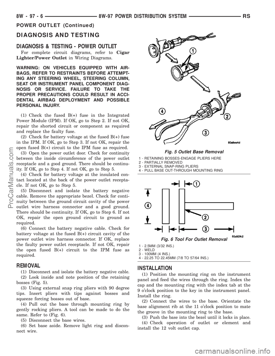
(1)Disconnect and isolate the battery negative cable.
(2) Look inside and note position of the retaining
bosses (Fig. 5).
(3) Using external snap ring pliers with 90 degree
tips. Insert pliers with tips against bosses and
squeeze forcing bosses out of base.
(4) Pull out the base through mounting ring by
gently rocking pliers. A tool can be made to do the
same. Refer to (Fig. 6).
(5) Disconnect the base wires.
(6) Set base aside. Remove light ring and discon-
nect wire.
INSTALLATION
(1) Position the mounting ring on the instrument
panel and feed the wires through the ring. Index the
cap and the mounting ring with the index tab at the
9 o'clock position to the key in the instrument panel.
Install the ring.
(2) Connect the wires to the base. Orientate the
base alignment rib at the 11 o'clock position to mate
the groove in the mounting ring to the base.
(3)
Push the base into the bezel until it locks in place.
(4) Check operation of outlet or element and
install the 12 volt outlet cap.
Fig. 5 Outlet Base Removal
1 - RETAINING BOSSES-ENGAGE PLIERS HERE
2 - PARTIALLY REMOVED
3 - EXTERNAL SNAP-RING PLIERS
4 - PULL BASE OUT-THROUGH MOUNTING RING
Fig. 6 Tool For Outlet Removal
1 - 2.5MM (3/32 INS.)
2 - WELD
3 - 100MM (4 INS.)
4 - 22.25 TO 22.45MM (7/8 TO 57/64 INS.)
8W - 97 - 6 8W-97 POWER DISTRIBUTION SYSTEMRS
POWER OUTLET (Continued)
ProCarManuals.com
Page 1232 of 2177
OIL
STANDARD PROCEDURE
ENGINE OIL LEVEL CHECK
The best time to check engine oil level is after it
has sat overnight, or if the engine has been running,
allow the engine to be shut off for at least 5 minutes
before checking oil level.
Checking the oil while the vehicle is on level
ground will improve the accuracy of the oil level
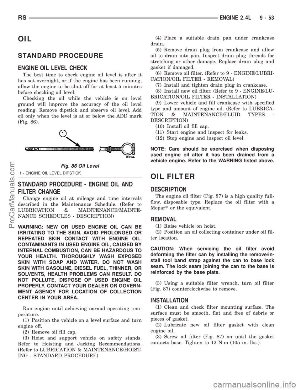
reading. Remove dipstick and observe oil level. Add
oil only when the level is at or below the ADD mark
(Fig. 86).
STANDARD PROCEDURE - ENGINE OIL AND
FILTER CHANGE
Change engine oil at mileage and time intervals
described in the Maintenance Schedule. (Refer to
LUBRICATION & MAINTENANCE/MAINTE-
NANCE SCHEDULES - DESCRIPTION)
WARNING: NEW OR USED ENGINE OIL CAN BE
IRRITATING TO THE SKIN. AVOID PROLONGED OR
REPEATED SKIN CONTACT WITH ENGINE OIL.
CONTAMINANTS IN USED ENGINE OIL, CAUSED BY
INTERNAL COMBUSTION, CAN BE HAZARDOUS TO
YOUR HEALTH. THOROUGHLY WASH EXPOSED
SKIN WITH SOAP AND WATER. DO NOT WASH
SKIN WITH GASOLINE, DIESEL FUEL, THINNER, OR
SOLVENTS, HEALTH PROBLEMS CAN RESULT. DO
NOT POLLUTE, DISPOSE OF USED ENGINE OIL
PROPERLY. CONTACT YOUR DEALER OR GOVERN-
MENT AGENCY FOR LOCATION OF COLLECTION
CENTER IN YOUR AREA.
Run engine until achieving normal operating tem-
perature.
(1) Position the vehicle on a level surface and turn
engine off.
(2) Remove oil fill cap.
(3) Hoist and support vehicle on safety stands.
Refer to Hoisting and Jacking Recommendations.
(Refer to LUBRICATION & MAINTENANCE/HOIST-
ING - STANDARD PROCEDURE)(4) Place a suitable drain pan under crankcase
drain.
(5) Remove drain plug from crankcase and allow
oil to drain into pan. Inspect drain plug threads for
stretching or other damage. Replace drain plug and
gasket if damaged.
(6) Remove oil filter. (Refer to 9 - ENGINE/LUBRI-
CATION/OIL FILTER - REMOVAL)
(7) Install and tighten drain plug in crankcase.
(8) Install new oil filter. (Refer to 9 - ENGINE/LU-
BRICATION/OIL FILTER - INSTALLATION)
(9) Lower vehicle and fill crankcase with specified
type and amount of engine oil. (Refer to LUBRICA-
TION & MAINTENANCE/FLUID TYPES -
DESCRIPTION)
(10) Install oil fill cap.
(11) Start engine and inspect for leaks.
(12) Stop engine and inspect oil level.
NOTE: Care should be exercised when disposing
used engine oil after it has been drained from a
vehicle engine. Refer to the WARNING listed above.
OIL FILTER
DESCRIPTION
The engine oil filter (Fig. 87) is a high quality full-
flow, disposable type. Replace the oil filter with a
Mopartor the equivalent.
REMOVAL
(1) Raise vehicle on hoist.
(2) Position an oil collecting container under oil fil-
ter location.
CAUTION: When servicing the oil filter avoid
deforming the filter can by installing the remove/in-
stall tool band strap against the can to base lock
seam. The lock seam joining the can to the base is
reinforced by the base plate.
(3) Using a suitable filter wrench, turn oil filter
(Fig. 87) counterclockwise to remove.
INSTALLATION
(1) Clean and check filter mounting surface. The
surface must be smooth, flat and free of debris or
pieces of gasket.
(2) Lubricate new oil filter gasket with clean
engine oil.
(3) Screw oil filter (Fig. 87) on until the gasket
contacts base. Tighten to 12 N´m (105 in. lbs.).
Fig. 86 Oil Level
1 - ENGINE OIL LEVEL DIPSTICK
RSENGINE 2.4L9-53
ProCarManuals.com
Page 1243 of 2177
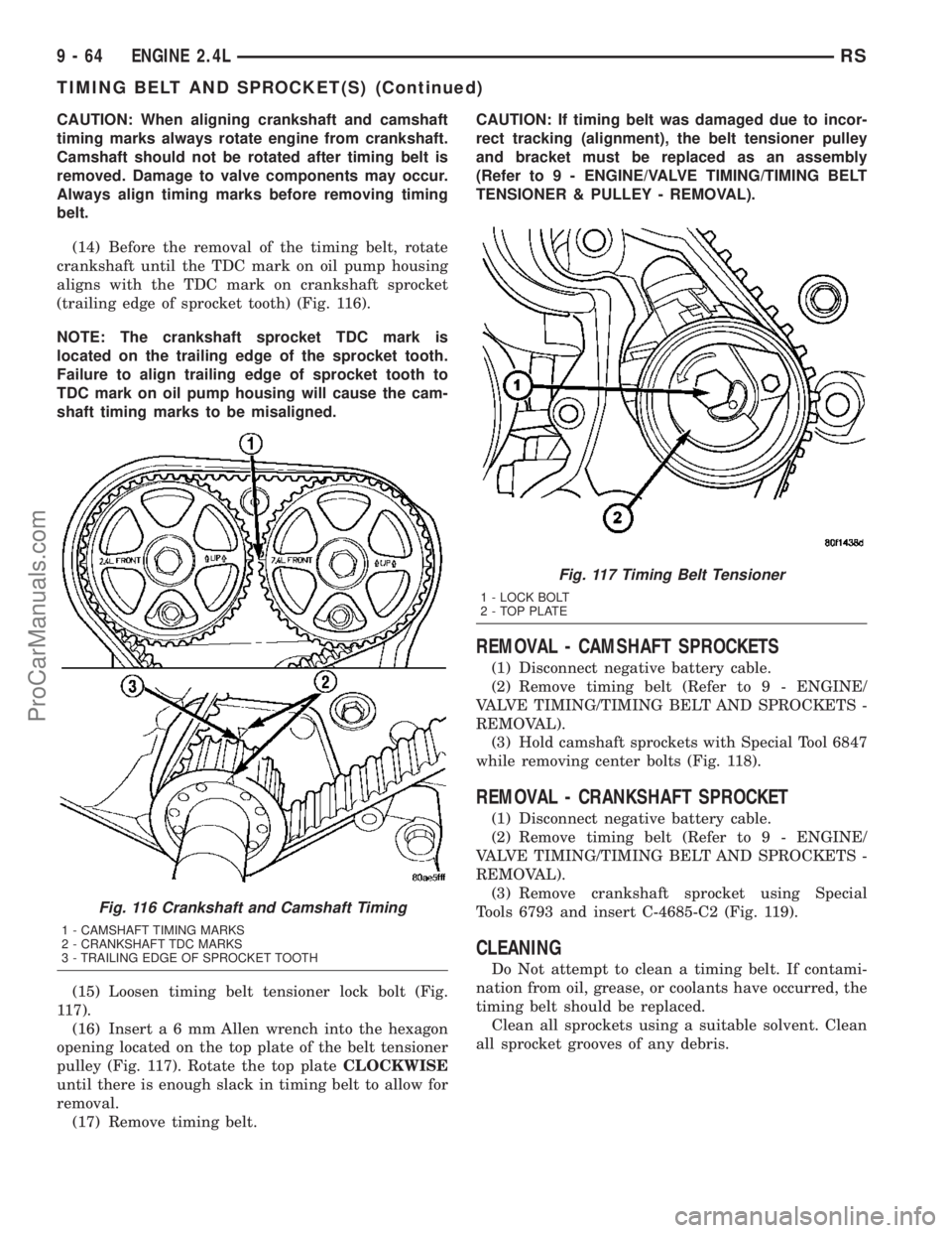
CAUTION: When aligning crankshaft and camshaft
timing marks always rotate engine from crankshaft.
Camshaft should not be rotated after timing belt is
removed. Damage to valve components may occur.
Always align timing marks before removing timing
belt.
(14) Before the removal of the timing belt, rotate
crankshaft until the TDC mark on oil pump housing
aligns with the TDC mark on crankshaft sprocket
(trailing edge of sprocket tooth) (Fig. 116).
NOTE: The crankshaft sprocket TDC mark is
located on the trailing edge of the sprocket tooth.
Failure to align trailing edge of sprocket tooth to
TDC mark on oil pump housing will cause the cam-
shaft timing marks to be misaligned.
(15) Loosen timing belt tensioner lock bolt (Fig.
117).
(16) Inserta6mmAllen wrench into the hexagon
opening located on the top plate of the belt tensioner
pulley (Fig. 117). Rotate the top plateCLOCKWISE
until there is enough slack in timing belt to allow for
removal.
(17) Remove timing belt.CAUTION: If timing belt was damaged due to incor-
rect tracking (alignment), the belt tensioner pulley
and bracket must be replaced as an assembly
(Refer to 9 - ENGINE/VALVE TIMING/TIMING BELT
TENSIONER & PULLEY - REMOVAL).
REMOVAL - CAMSHAFT SPROCKETS
(1) Disconnect negative battery cable.
(2) Remove timing belt (Refer to 9 - ENGINE/
VALVE TIMING/TIMING BELT AND SPROCKETS -
REMOVAL).
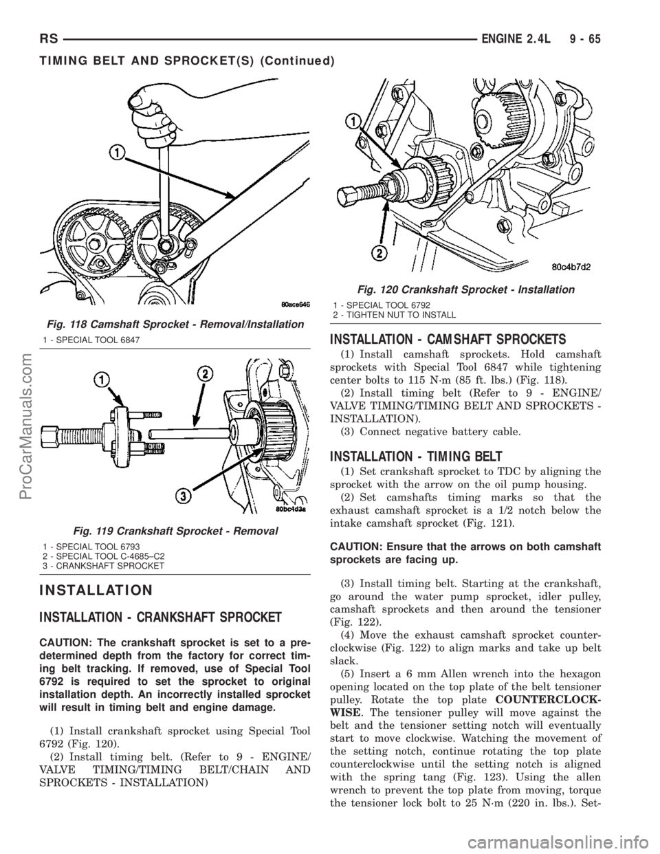
(3) Hold camshaft sprockets with Special Tool 6847
while removing center bolts (Fig. 118).
REMOVAL - CRANKSHAFT SPROCKET
(1) Disconnect negative battery cable.
(2) Remove timing belt (Refer to 9 - ENGINE/
VALVE TIMING/TIMING BELT AND SPROCKETS -
REMOVAL).
(3) Remove crankshaft sprocket using Special
Tools 6793 and insert C-4685-C2 (Fig. 119).
CLEANING
Do Not attempt to clean a timing belt. If contami-
nation from oil, grease, or coolants have occurred, the
timing belt should be replaced.
Clean all sprockets using a suitable solvent. Clean
all sprocket grooves of any debris.
Fig. 116 Crankshaft and Camshaft Timing
1 - CAMSHAFT TIMING MARKS
2 - CRANKSHAFT TDC MARKS
3 - TRAILING EDGE OF SPROCKET TOOTH
Fig. 117 Timing Belt Tensioner
1 - LOCK BOLT
2 - TOP PLATE
9 - 64 ENGINE 2.4LRS
TIMING BELT AND SPROCKET(S) (Continued)
ProCarManuals.com
Page 1244 of 2177
INSTALLATION
INSTALLATION - CRANKSHAFT SPROCKET
CAUTION: The crankshaft sprocket is set to a pre-
determined depth from the factory for correct tim-
ing belt tracking. If removed, use of Special Tool
6792 is required to set the sprocket to original
installation depth. An incorrectly installed sprocket
will result in timing belt and engine damage.
(1) Install crankshaft sprocket using Special Tool
6792 (Fig. 120).
(2) Install timing belt. (Refer to 9 - ENGINE/
VALVE TIMING/TIMING BELT/CHAIN AND
SPROCKETS - INSTALLATION)
INSTALLATION - CAMSHAFT SPROCKETS
(1) Install camshaft sprockets. Hold camshaft
sprockets with Special Tool 6847 while tightening
center bolts to 115 N´m (85 ft. lbs.) (Fig. 118).
(2) Install timing belt (Refer to 9 - ENGINE/
VALVE TIMING/TIMING BELT AND SPROCKETS -
INSTALLATION).
(3) Connect negative battery cable.
INSTALLATION - TIMING BELT
(1) Set crankshaft sprocket to TDC by aligning the
sprocket with the arrow on the oil pump housing.
(2) Set camshafts timing marks so that the
exhaust camshaft sprocket is a 1/2 notch below the
intake camshaft sprocket (Fig. 121).
CAUTION: Ensure that the arrows on both camshaft
sprockets are facing up.
(3) Install timing belt. Starting at the crankshaft,
go around the water pump sprocket, idler pulley,
camshaft sprockets and then around the tensioner
(Fig. 122).
(4) Move the exhaust camshaft sprocket counter-
clockwise (Fig. 122) to align marks and take up belt
slack.
(5) Inserta6mmAllen wrench into the hexagon
opening located on the top plate of the belt tensioner
pulley. Rotate the top plateCOUNTERCLOCK-
WISE. The tensioner pulley will move against the
belt and the tensioner setting notch will eventually
start to move clockwise. Watching the movement of
the setting notch, continue rotating the top plate
counterclockwise until the setting notch is aligned
with the spring tang (Fig. 123). Using the allen
wrench to prevent the top plate from moving, torque
the tensioner lock bolt to 25 N´m (220 in. lbs.). Set-
Fig. 118 Camshaft Sprocket - Removal/Installation
1 - SPECIAL TOOL 6847
Fig. 119 Crankshaft Sprocket - Removal
1 - SPECIAL TOOL 6793
2 - SPECIAL TOOL C-4685±C2
3 - CRANKSHAFT SPROCKET
Fig. 120 Crankshaft Sprocket - Installation
1 - SPECIAL TOOL 6792
2 - TIGHTEN NUT TO INSTALL
RSENGINE 2.4L9-65
TIMING BELT AND SPROCKET(S) (Continued)
ProCarManuals.com
Page 1245 of 2177
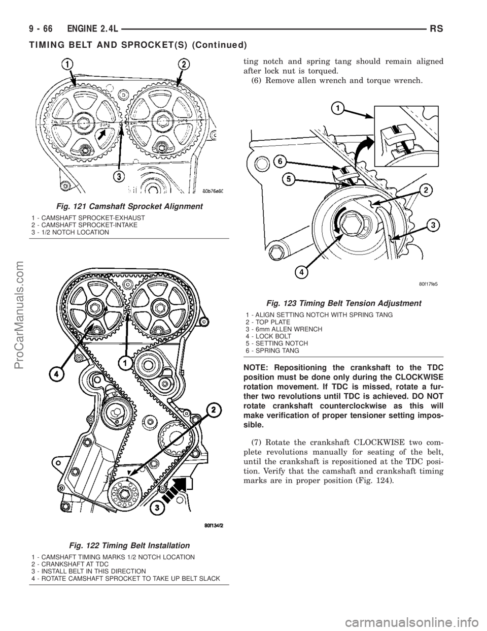
ting notch and spring tang should remain aligned
after lock nut is torqued.
(6) Remove allen wrench and torque wrench.
NOTE: Repositioning the crankshaft to the TDC
position must be done only during the CLOCKWISE
rotation movement. If TDC is missed, rotate a fur-
ther two revolutions until TDC is achieved. DO NOT
rotate crankshaft counterclockwise as this will
make verification of proper tensioner setting impos-
sible.
(7) Rotate the crankshaft CLOCKWISE two com-
plete revolutions manually for seating of the belt,
until the crankshaft is repositioned at the TDC posi-
tion. Verify that the camshaft and crankshaft timing
marks are in proper position (Fig. 124).
Fig. 121 Camshaft Sprocket Alignment
1 - CAMSHAFT SPROCKET-EXHAUST
2 - CAMSHAFT SPROCKET-INTAKE
3 - 1/2 NOTCH LOCATION
Fig. 122 Timing Belt Installation
1 - CAMSHAFT TIMING MARKS 1/2 NOTCH LOCATION
2 - CRANKSHAFT AT TDC
3 - INSTALL BELT IN THIS DIRECTION
4 - ROTATE CAMSHAFT SPROCKET TO TAKE UP BELT SLACK
Fig. 123 Timing Belt Tension Adjustment
1 - ALIGN SETTING NOTCH WITH SPRING TANG
2 - TOP PLATE
3 - 6mm ALLEN WRENCH
4 - LOCK BOLT
5 - SETTING NOTCH
6 - SPRING TANG
9 - 66 ENGINE 2.4LRS
TIMING BELT AND SPROCKET(S) (Continued)
ProCarManuals.com
Page 1252 of 2177
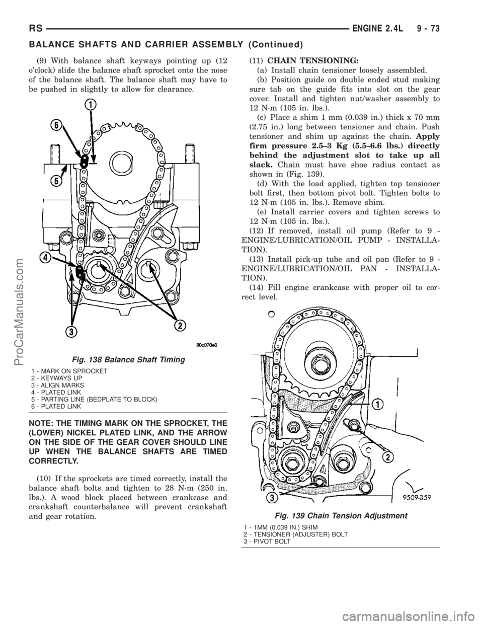
(9) With balance shaft keyways pointing up (12
o'clock) slide the balance shaft sprocket onto the nose
of the balance shaft. The balance shaft may have to
be pushed in slightly to allow for clearance.
NOTE: THE TIMING MARK ON THE SPROCKET, THE
(LOWER) NICKEL PLATED LINK, AND THE ARROW
ON THE SIDE OF THE GEAR COVER SHOULD LINE
UP WHEN THE BALANCE SHAFTS ARE TIMED
CORRECTLY.
(10) If the sprockets are timed correctly, install the
balance shaft bolts and tighten to 28 N´m (250 in.
lbs.). A wood block placed between crankcase and
crankshaft counterbalance will prevent crankshaft
and gear rotation.(11)CHAIN TENSIONING:
(a) Install chain tensioner loosely assembled.
(b) Position guide on double ended stud making
sure tab on the guide fits into slot on the gear
cover. Install and tighten nut/washer assembly to
12 N´m (105 in. lbs.).
(c) Place a shim 1 mm (0.039 in.) thick x 70 mm
(2.75 in.) long between tensioner and chain. Push
tensioner and shim up against the chain.Apply
firm pressure 2.5±3 Kg (5.5±6.6 lbs.) directly
behind the adjustment slot to take up all
slack.Chain must have shoe radius contact as
shown in (Fig. 139).
(d) With the load applied, tighten top tensioner
bolt first, then bottom pivot bolt. Tighten bolts to
12 N´m (105 in. lbs.). Remove shim.
(e) Install carrier covers and tighten screws to
12 N´m (105 in. lbs.).
(12) If removed, install oil pump (Refer to 9 -
ENGINE/LUBRICATION/OIL PUMP - INSTALLA-
TION).
(13) Install pick-up tube and oil pan (Refer to 9 -
ENGINE/LUBRICATION/OIL PAN - INSTALLA-
TION).
(14) Fill engine crankcase with proper oil to cor-
rect level.
Fig. 138 Balance Shaft Timing
1 - MARK ON SPROCKET
2 - KEYWAYS UP
3 - ALIGN MARKS
4 - PLATED LINK
5 - PARTING LINE (BEDPLATE TO BLOCK)
6 - PLATED LINK
Fig. 139 Chain Tension Adjustment
1 - 1MM (0.039 IN.) SHIM
2 - TENSIONER (ADJUSTER) BOLT
3 - PIVOT BOLT
RSENGINE 2.4L9-73
BALANCE SHAFTS AND CARRIER ASSEMBLY (Continued)
ProCarManuals.com