location CHRYSLER CARAVAN 2005 Owner's Guide
[x] Cancel search | Manufacturer: CHRYSLER, Model Year: 2005, Model line: CARAVAN, Model: CHRYSLER CARAVAN 2005Pages: 2339, PDF Size: 59.69 MB
Page 274 of 2339
CAUTION: Pulling the antenna cable straight out of
the radio without pulling on the locking antenna
connector could damage the cable or radio.
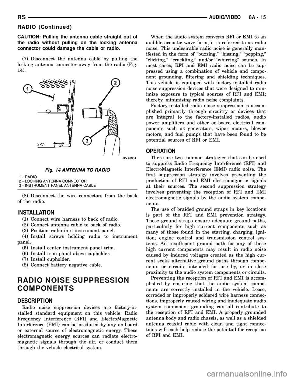
(7) Disconnect the antenna cable by pulling the
locking antenna connector away from the radio (Fig.
14).
(8) Disconnect the wire connectors from the back
of the radio.
INSTALLATION
(1) Connect wire harness to back of radio.
(2) Connect antenna cable to back of radio.
(3) Position radio into instrument panel.
(4) Install screws holding radio to instrument
panel.
(5) Install center instrument panel trim.
(6) Install trim panel above cupholder.
(7) Install cupholder.
(8) Connect battery negative cable.
RADIO NOISE SUPPRESSION
COMPONENTS
DESCRIPTION
Radio noise suppression devices are factory-in-
stalled standard equipment on this vehicle. Radio
Frequency Interference (RFI) and ElectroMagnetic
Interference (EMI) can be produced by any on-board
or external source of electromagnetic energy. These
electromagnetic energy sources can radiate electro-
magnetic signals through the air, or conduct them
through the vehicle electrical system.When the audio system converts RFI or EMI to an
audible acoustic wave form, it is referred to as radio
noise. This undesirable radio noise is generally man-
ifested in the form of ªbuzzing,º ªhissing,º ªpopping,º
ªclicking,º ªcrackling,º and/or ªwhirringº sounds. In
most cases, RFI and EMI radio noise can be sup-
pressed using a combination of vehicle and compo-
nent grounding, filtering and shielding techniques.
This vehicle is equipped with factory-installed radio
noise suppression devices that were designed to min-
imize exposure to typical sources of RFI and EMI;
thereby, minimizing radio noise complaints.
Factory-installed radio noise suppression is accom-
plished primarily through circuitry or devices that
are integral to the factory-installed radios, audio
power amplifiers and other on-board electrical com-
ponents such as generators, wiper motors, blower
motors, and fuel pumps that have been found to be
potential sources of RFI or EMI.
OPERATION
There are two common strategies that can be used
to suppress Radio Frequency Interference (RFI) and
ElectroMagnetic Interference (EMI) radio noise. The
first suppression strategy involves preventing the
production of RFI and EMI electromagnetic signals
at their sources. The second suppression strategy
involves preventing the reception of RFI and EMI
electromagnetic signals by the audio system compo-
nents.
The use of braided ground straps in key locations
is part of the RFI and EMI prevention strategy.
These ground straps ensure adequate ground paths,
particularly for high current components such as
many of those found in the starting, charging, igni-
tion, engine control and transmission control sys-
tems. An insufficient ground path for any of these
high current components may result in radio noise
caused by induced voltages created as the high cur-
rent seeks alternative ground paths through compo-
nents or circuits intended for use by, or in close
proximity to the audio system components or circuits.
Preventing the reception of RFI and EMI is accom-
plished by ensuring that the audio system compo-
nents are correctly installed in the vehicle. Loose,
corroded or improperly soldered wire harness connec-
tions, improperly routed wiring and inadequate audio
system component grounding can all contribute to
the reception of RFI and EMI. A properly grounded
antenna body and radio chassis, as well as a shielded
antenna coaxial cable with clean and tight connec-
tions will each help reduce the potential for reception
of RFI and EMI.
Fig. 14 ANTENNA TO RADIO
1 - RADIO
2 - LOCKING ANTENNA CONNECTOR
3 - INSTRUMENT PANEL ANTENNA CABLE
RSAUDIO/VIDEO8A-15
RADIO (Continued)
Page 277 of 2339
SPEAKER
DIAGNOSIS AND TESTING
SPEAKER
WARNING: DISABLE THE AIRBAG SYSTEM
BEFORE ATTEMPTING ANY STEERING WHEEL,
STEERING COLUMN, SEAT BELT TENSIONER, SIDE
AIRBAG, OR INSTRUMENT PANEL COMPONENT
DIAGNOSIS OR SERVICE. DISCONNECT AND ISO-
LATE THE BATTERY NEGATIVE (GROUND) CABLE,
THEN WAIT TWO MINUTES FOR THE AIRBAG SYS-
TEM CAPACITOR TO DISCHARGE BEFORE PER-
FORMING FURTHER DIAGNOSIS OR SERVICE. THIS
IS THE ONLY SURE WAY TO DISABLE THE AIRBAG
SYSTEM. FAILURE TO TAKE THE PROPER PRE-
CAUTIONS COULD RESULT IN ACCIDENTAL AIR-
BAG DEPLOYMENT AND POSSIBLE PERSONAL
INJURY.
Any diagnosis of the Audio system should
begin with the use of the DRB IIItdiagnostic
tool. For information on the use of the DRB
IIIt, refer to the appropriate Diagnostic Service
Manual.
(1) If all speakers are inoperative, check the radio
fuses in the Junction Block (JB). If OK, go to Step 2.
If not OK, repair the shorted circuit or component as
required and replace the faulty fuse.
(2) Check the amplifier fuse (if equipped) in the
junction block. If OK, go to Step 3. If not OK, repair
the shorted circuit or component as required and
replace the faulty fuse.
(3) Turn the ignition switch to the ON position.
Turn the radio receiver ON. Adjust the balance and
fader control controls to check the performance of
each individual speaker. Note the speaker locations
that are not performing correctly. Go to Step 4.
(4) Turn the radio receiver OFF. Turn the ignition
OFF. Disconnect and isolate the battery negative
cable. If vehicle isnotequipped with a amplifier,
remove the radio receiver. If vehicle is equipped with
an amplifier. disconnect wire harness connector at
output side of amplifier. Go to Step 4.
(5) Check both the speaker feed (+) circuit and
return (-) circuit cavities for the inoperative speaker
at the radio receiver wire harness connector for con-
tinuity to ground. There should be no continuity. If
OK, go to Step 5. If not OK, repair the shorted
speaker feed (+) and/or return (-) circuits(s) to the
speaker as required.(6) Disconnect wire harness connector at the inop-
erative speaker. Check for continuity between the
speaker feed (+) circuit cavities of the radio receiver
wire harness connector or if equipped, the amplifier
wire harness connector and the speaker wire harness
connector. Repeat the check between the speaker
return (-) circuit cavities of the radio receiver wire
harness connector and the speaker wire harness con-
nector. In each case, there should be continuity. If
OK, replace the faulty speaker. If not OK, repair the
open speaker feed (+) and/or return (-) circuits(s) as
required.
REMOVAL
D-PILLAR SPEAKER
(1) Disconnect and isolate the battery negative
cable.
(2) Remove rear header trim (right side speaker).
(3) Remove jack cover (left side speaker).
(4) Remove liftgate scuff plate.
(5) Remove upper seat belt bolt. (Refer to 8 -
ELECTRICAL/RESTRAINTS/SEAT BELT OUT-
BOARD FRONT - REMOVAL).
(6) Partially remove quarter trim panel to access
the D-pillar speaker.
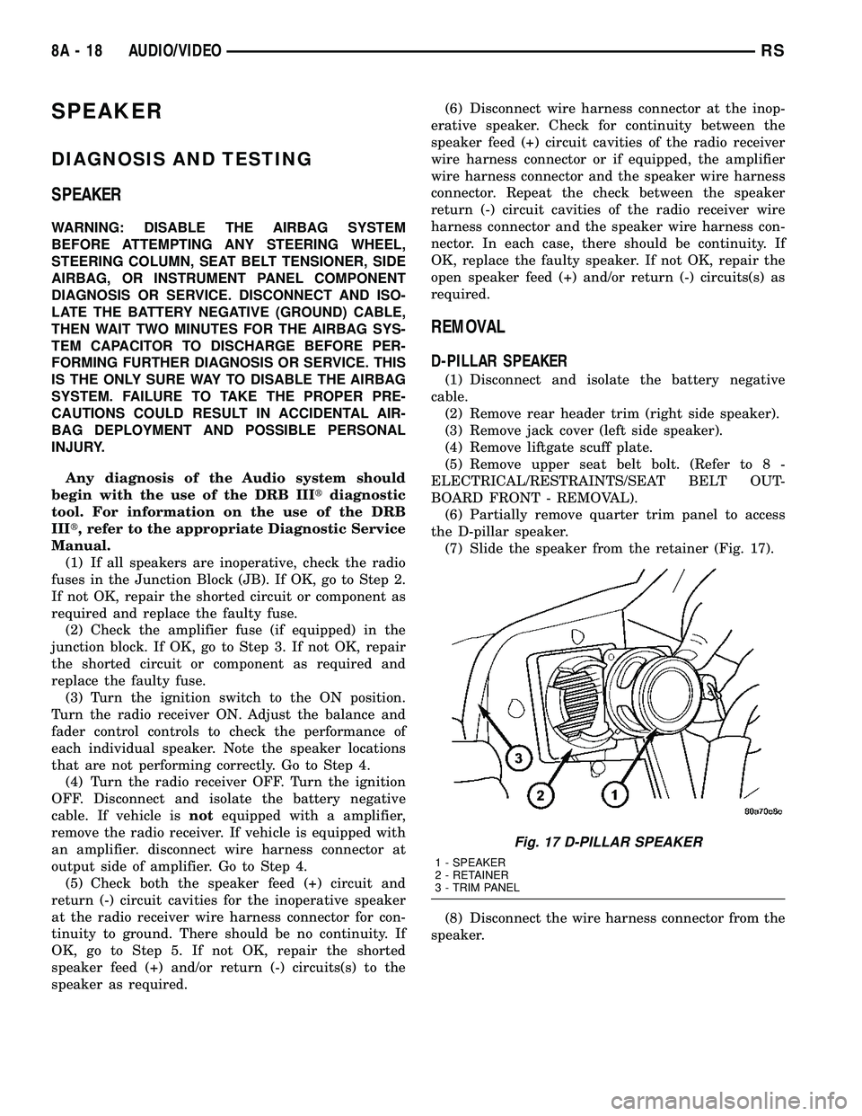
(7) Slide the speaker from the retainer (Fig. 17).
(8) Disconnect the wire harness connector from the
speaker.
Fig. 17 D-PILLAR SPEAKER
1 - SPEAKER
2 - RETAINER
3 - TRIM PANEL
8A - 18 AUDIO/VIDEORS
Page 281 of 2339
PARK ASSIST SYSTEM
The Park Assist System display activates an audi-
ble tone that changes from intermittent to continu-
ous as the final two Light Emitting Diodes (LED's)
are illuminated on one side or both sides of the dis-
play.
The system detection length from the rear of the
vehicle is 0.3 meters to 1.5 meters. This area extends
around the rear side of the vehicle. The system detec-
tion height from the ground is 0.2 meters to about
1.5 meters. The radio mutes when the system acti-
vates its audible tone.
When the driver selects Reverse the system scans
for objects behind the vehicle using four sensors
located in the rear bumper. A warning display above
the rear window provides both visible and audible
warnings indicating the range of the object.
The system is active only when the transmission
gear selector is in reverse for vehicle speeds less than
16 Km/h (10 mph). If the vehicle's Parking/Emer-
gency Brake is applied, the system is deactivated.
The display contains two sets of yellow and red
Light Emitting Diode's (LED's) that the driver can
see as they look over their shoulder while backing
up. Each side of the vehicle has its own warning
LED's. The system provides a visual warning by illu-
minating one or more yellow LED's as the vehicle
gets closer to the object. As the vehicle continues to
approach the object, one red LED is illuminated and
the system emits a series of short beeps. The tone
will remain constant and both red LED's are illumi-
nated once the vehicle is within 12 inches (30.5 cm)
of the object.
The system can be turned ON or OFF through the
Electronic Vehicle Information Center (EVIC) when
the vehicle is in PARK. If the park assist system is
turned OFF, a single chime will sound and the EVIC
will display the following message ªREAR PARK
ASSIST OFFº, when the vehicle is in reverse.
²Ensure that the rear bumper is free of dirt and
debris to keep the system operating properly.
²Jackhammers, large trucks, and other vibrations
could affect the performance of the system.
²Ensure that the parking brake is not applied.
If ªService Park Assist Systemº appears in the
EVIC after making sure the rear bumper is clean,
proceed to diagnose the system using a scan tool and
the appropriate diagnostic information.
WARNING
On vehicles equipped with airbags, disable
the airbag system before attempting any steer-
ing wheel, steering column, or instrument
panel component diagnosis or service. Discon-
nect and isolate the battery negative (ground)
cable, then wait two minutes for the airbag sys-
tem capacitor to discharge before performing
further diagnosis or service. This is the only
sure way to disable the airbag system. Failure
to take the proper precautions could result in
accidental airbag deployment, personal injury,
or death.
DIAGNOSIS AND TESTING - CHIME SYSTEM
Refer to the proper Body Diagnostic Procedures
manual for complete Diagnosis and Testing of the
Chime System.
NO TONE WHEN IGNITION SWITCH IS TURNED ON
AND DRIVER'S SEAT BELT IS NOT BUCKLED.
(1) Using a DRB llltscan tool, actuate chime
(BCM actuates).
(2) Using a voltmeter, check for voltage:
(a) BCM has two battery feeds at pin 1 and pin
5 of the 6±way connector.
(b) Pin 5 of the (BX2) 32 way connector of the
BCM for ignition feed.
(c) Check voltage (PX2) connector, pin 34 for 12v.
(d) If voltage OK, go to step Step 3
(e) If NO voltage repair as necessary. Refer to
the appropriate wiring information. The wiring
information includes wiring diagrams, proper wire
and connector repair procedures, further details on
wire harness routing and retention, as well as pin-
out and location views for the various wire harness
connectors, splices and grounds.
(3) Check drivers seat belt buckle switch input
(from Occupant Restraint Controller (ORC) for a
closed circuit when not buckled. If input not seen,
look for open in wiring or switch. The switch is
grounded when belt is not buckled.
(4) Verify Programmable Communication Interface
(PCI) data bus communication between ORC and
BCM.
8B - 2 CHIME/BUZZERRS
CHIME/BUZZER (Continued)
Page 284 of 2339
²System diagnostics - diagnosis and error han-
dling (sensors, display, module).
²Data exchange over the Programmable Commu-
nication Interface (PCI) data bus.
OPERATION
The module has a number of functions:
²Supply voltage to the sensors and display.
²Disconnection of the display with bus idle and
over voltage Vmax.
²Triggering the sensors.
²Analyze echo delay times and calculate obstacle
distances.
²Bi-directional data communication to the display
for diagnosis.
²System diagnostics - diagnosis and error han-
dling (sensors, display, module).
²Data exchange over the Programmable Commu-
nication Interface (PCI) data bus.
The system detection length from the rear of the
vehicle is 0.3 meters to 1.5 meters. This area extends
around the rear side of the vehicle. The system detec-
tion height from the ground is 0.2 meters to about
1.5 meters. The radio mutes when the system acti-
vates its audible tone.When the driver selects Reverse, the system scans
for objects behind the vehicle using four sensors
located in the rear bumper. Objects can be detected
from up to 1.5 meters. A warning display above the
rear window provides both visible and audible warn-
ings indicating the range of the object.
The system is active only when the vehicle is in
reverse for vehicle speeds less than 16 Km/h (10
mph). If the vehicles Parking/Emergency Brake is
applied, the system is deactivated.
The display contains two sets of yellow and red
Light Emitting Diode's (LED's) that the driver can
see as they look over their shoulder while backing
up. Each side of the vehicle has its own warning
LED's. The system provides a visual warning by illu-
minating one or more yellow LED's as the vehicle
gets closer to the object. As the vehicle continues to
approaches the object, one red LED is illuminated
and the system emits a series of short beeps. The
tone will remain constant and both red LED's are
illuminated once the vehicle is within 12 inches (30.5
cm) of the object.
The system can be turned ON or OFF through the
Electronic Vehicle Information Center (EVIC) when
the vehicle is in PARK. If the park assist system is
turned OFF, a single chime will sound and the EVIC
will display the following message ªREAR PARK
ASSIST OFFº, when the vehicle is in reverse.
²Ensure that the rear bumper is free of dirt and
debris to keep the system operating properly.
²Jackhammers, large trucks, and other vibrations
could affect the performance of the system.
²Ensure that the parking brake is not applied.
If ªService Park Assist Systemº appears in the
EVIC after making sure the rear bumper is clean,
proceed to diagnose the system using a scan tool and
the appropriate diagnostic information.
To diagnose the Park Assist Module, use a scan
tool and the appropriate body diagnostic information.
REMOVAL
(1) Open hood.
(2)
Disconnect and isolate the battery negative cable.
(3) Remove the left quarter trim panel (Refer to 23
- BODY/INTERIOR/QUARTER TRIM PANEL -
REMOVAL).
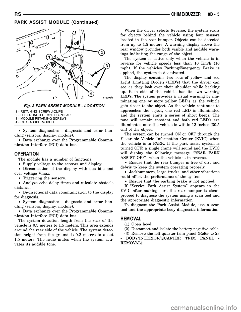
Fig. 3 PARK ASSIST MODULE - LOCATION
1 - RETAINING SCREW J-CLIPS
2 - LEFT QUARTER PANEL/C-PILLAR
3 - MODULE RETAINING SCREWS
4 - PARK ASSIST MODULE
RSCHIME/BUZZER8B-5
PARK ASSIST MODULE (Continued)
Page 285 of 2339
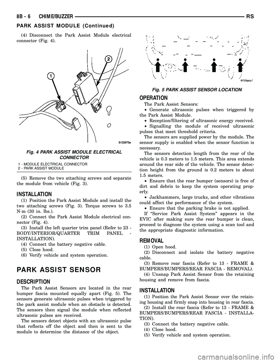
(4) Disconnect the Park Assist Module electrical
connector (Fig. 4).
(5) Remove the two attaching screws and separate
the module from vehicle (Fig. 3).
INSTALLATION
(1) Position the Park Assist Module and install the
two attaching screws (Fig. 3). Torque screws to 3.5
N´m (30 in. lbs.).
(2) Connect the Park Assist Module electrical con-
nector (Fig. 4).
(3) Install the left quarter trim panel (Refer to 23 -
BODY/INTERIOR/QUARTER TRIM PANEL -
INSTALLATION).
(4) Connect the battery negative cable.
(5) Close hood.
(6) Verify vehicle and system operation.
PARK ASSIST SENSOR
DESCRIPTION
The Park Assist Sensors are located in the rear
bumper fascia mounted equally apart (Fig. 5). The
sensors generate ultrasonic pulses when triggered by
the park assist module when an obstacle is detected.
The sensors then signal the module when reflected
ultrasonic pulses are received.
The sensors detect objects with an ultrasonic pulse
that reflects off the object and then is sent to the
module to determine the distance of the object.
OPERATION
The Park Assist Sensors:
²Generate ultrasonic pulses when triggered by
the Park Assist Module.
²Reception/filtering of ultrasonic energy received.
²Signalling the module of received ultrasonic
pulses that meet threshold criteria.
The sensors are supplied power by the module. The
sensor supply is enabled when the sensor function is
necessary.
The sensors detection length from the rear of the
vehicle is 0.3 meters to 1.5 meters. This area extends
around the rear side of the vehicle. The sensor detec-
tion height from the ground is 0.2 meters to about
1.5 meters.
²Ensure that the rear bumper (sensors) is free of
dirt and debris to keep the system operating prop-
erly.
²Jackhammers, large trucks, and other vibrations
could affect the performance of the system.
²Ensure that the parking brake is not applied.
If ªService Park Assist Systemº appears in the
EVIC after making sure the rear bumper is clean,
proceed to diagnose the system using a scan tool and
the appropriate diagnostic information.
REMOVAL
(1) Open hood.
(2) Disconnect and isolate the battery negative
cable.
(3) Remove rear fascia (Refer to 13 - FRAME &
BUMPERS/BUMPERS/REAR FASCIA - REMOVAL).
(4) Unsnap Park Assist Sensor from the retaining
housing and remove from fascia.
INSTALLATION
(1)Position the Park Assist Sensor over the retain-
ing housing and firmly snap into housing in rear fascia.
(2) Install the rear fascia (Refer to 13 - FRAME &
BUMPERS/BUMPERS/REAR FASCIA - INSTALLA-
TION).
(3) Connect the battery negative cable.
(4) Close hood.
(5) Verify vehicle and system operation.
Fig. 4 PARK ASSIST MODULE ELECTRICAL
CONNECTOR
1 - MODULE ELECTRICAL CONNECTOR
2 - PARK ASSIST MODULE
Fig. 5 PARK ASSIST SENSOR LOCATION
8B - 6 CHIME/BUZZERRS
PARK ASSIST MODULE (Continued)
Page 301 of 2339
(1) Plug the DRBIIItscan tool into the diagnostic
connector. The connector is located under the instru-
ment panel.
(2) Go to the Transmission screen.
(3) Go to the Miscellaneous screen.
(4) Select Quick Learn Procedure. Follow the
instructions of the DRBIIItto perform the Quick
Learn Procedure.
REMOVAL
REMOVAL - SBEC CONTROLLER
(1) Disconnect the negative battery cable.
(2) Remove the battery shield, refer to the Battery
section for more information.
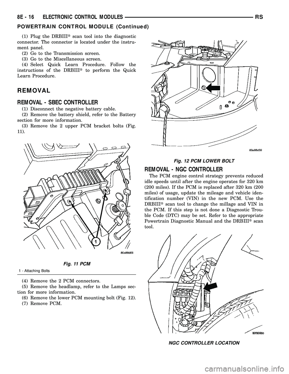
(3) Remove the 2 upper PCM bracket bolts (Fig.
11).
(4) Remove the 2 PCM connectors.
(5) Remove the headlamp, refer to the Lamps sec-
tion for more information.
(6) Remove the lower PCM mounting bolt (Fig. 12).
(7) Remove PCM.
REMOVAL - NGC CONTROLLER
The PCM engine control strategy prevents reduced
idle speeds until after the engine operates for 320 km
(200 miles). If the PCM is replaced after 320 km (200
miles) of usage, update the mileage and vehicle iden-
tification number (VIN) in the new PCM. Use the
DRBIIItscan tool to change the millage and VIN in
the PCM. If this step is not done a Diagnostic Trou-
ble Code (DTC) may be set. Refer to the appropriate
Powertrain Diagnostic Manual and the DRBIIItscan
tool.
Fig. 11 PCM
1 - Attaching Bolts
Fig. 12 PCM LOWER BOLT
NGC CONTROLLER LOCATION
8E - 16 ELECTRONIC CONTROL MODULESRS
POWERTRAIN CONTROL MODULE (Continued)
Page 306 of 2339
ENGINE SYSTEMS
TABLE OF CONTENTS
page page
BATTERY SYSTEM......................... 1
CHARGING.............................. 21STARTING............................... 31
BATTERY SYSTEM
TABLE OF CONTENTS
page page
BATTERY SYSTEM
DESCRIPTION..........................1
OPERATION............................2
DIAGNOSIS AND TESTING
BATTERY SYSTEM.....................2
CLEANING.............................5
INSPECTION...........................5
SPECIFICATIONS
BATTERY............................6
SPECIAL TOOLS
BATTERY SYSTEM SPECIAL TOOLS.......7
BATTERY
DESCRIPTION..........................7
OPERATION............................9
DIAGNOSIS AND TESTING
BATTERY............................9
STANDARD PROCEDURE
SPIRAL PLATE BATTERY CHARGING......10
CONVENTIONAL BATTERY CHARGING....11
OPEN-CIRCUIT VOLTAGE TEST..........13IGNITION-OFF DRAW TEST.............13
CHECKING BATTERY ELECTROLYTE
LEVEL..............................14
MICRO 420 BATTERY TESTER...........15
REMOVAL - BATTERY...................16
INSTALLATION.........................16
BATTERY HOLDDOWN
REMOVAL.............................16
INSTALLATION.........................16
BATTERY CABLES
DESCRIPTION.........................16
OPERATION...........................17
DIAGNOSIS AND TESTING
BATTERY CABLES....................17
REMOVAL.............................19
INSTALLATION.........................19
BATTERY TRAY
DESCRIPTION.........................19
REMOVAL.............................19
INSTALLATION.........................20
BATTERY SYSTEM
DESCRIPTION
This vehicle is equipped with a single 12-volt bat-
tery. All of the components of the battery system are
located within the engine compartment. The battery
system for this vehicle contains the following related
components:
²Battery- The storage battery provides a reli-
able means of storing a renewable source of electrical
energy within the vehicle.
²Battery Cable- The battery cables connect the
battery terminal posts to the vehicle electrical sys-
tem.²Battery Holddown- The battery holddown
hardware secures the battery in the battery tray in
the engine compartment.
²Battery Thermowrap- The battery thermow-
rap insulates the battery to protect it from engine
compartment temperature extremes.
²Battery Tray- The battery tray provides a
secure mounting location in the vehicle for the bat-
tery and an anchor point for the battery holddown
hardware.
RSENGINE SYSTEMS8F-1
Page 320 of 2339
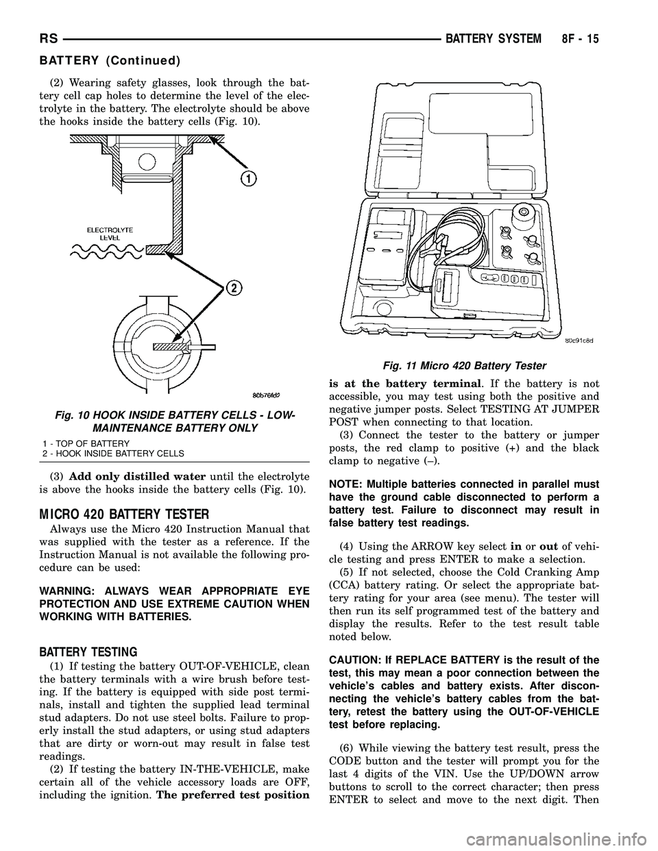
(2) Wearing safety glasses, look through the bat-
tery cell cap holes to determine the level of the elec-
trolyte in the battery. The electrolyte should be above
the hooks inside the battery cells (Fig. 10).
(3)Add only distilled wateruntil the electrolyte
is above the hooks inside the battery cells (Fig. 10).
MICRO 420 BATTERY TESTER
Always use the Micro 420 Instruction Manual that
was supplied with the tester as a reference. If the
Instruction Manual is not available the following pro-
cedure can be used:
WARNING: ALWAYS WEAR APPROPRIATE EYE
PROTECTION AND USE EXTREME CAUTION WHEN
WORKING WITH BATTERIES.
BATTERY TESTING
(1) If testing the battery OUT-OF-VEHICLE, clean
the battery terminals with a wire brush before test-
ing. If the battery is equipped with side post termi-
nals, install and tighten the supplied lead terminal
stud adapters. Do not use steel bolts. Failure to prop-
erly install the stud adapters, or using stud adapters
that are dirty or worn-out may result in false test
readings.
(2) If testing the battery IN-THE-VEHICLE, make
certain all of the vehicle accessory loads are OFF,
including the ignition.The preferred test positionis at the battery terminal. If the battery is not
accessible, you may test using both the positive and
negative jumper posts. Select TESTING AT JUMPER
POST when connecting to that location.
(3) Connect the tester to the battery or jumper
posts, the red clamp to positive (+) and the black
clamp to negative (±).
NOTE: Multiple batteries connected in parallel must
have the ground cable disconnected to perform a
battery test. Failure to disconnect may result in
false battery test readings.
(4) Using the ARROW key selectinoroutof vehi-
cle testing and press ENTER to make a selection.
(5) If not selected, choose the Cold Cranking Amp
(CCA) battery rating. Or select the appropriate bat-
tery rating for your area (see menu). The tester will
then run its self programmed test of the battery and
display the results. Refer to the test result table
noted below.
CAUTION: If REPLACE BATTERY is the result of the
test, this may mean a poor connection between the
vehicle's cables and battery exists. After discon-
necting the vehicle's battery cables from the bat-
tery, retest the battery using the OUT-OF-VEHICLE
test before replacing.
(6) While viewing the battery test result, press the
CODE button and the tester will prompt you for the
last 4 digits of the VIN. Use the UP/DOWN arrow
buttons to scroll to the correct character; then press
ENTER to select and move to the next digit. Then
Fig. 10 HOOK INSIDE BATTERY CELLS - LOW-
MAINTENANCE BATTERY ONLY
1 - TOP OF BATTERY
2 - HOOK INSIDE BATTERY CELLS
Fig. 11 Micro 420 Battery Tester
RSBATTERY SYSTEM8F-15
BATTERY (Continued)
Page 322 of 2339
are installed at the open end of the female battery
terminal clamp. Large eyelet type terminals are
crimped onto the opposite end of the battery cable
wire and then solder-dipped. The battery positive
cable wires have a red insulating jacket to provide
visual identification and feature a larger female bat-
tery terminal clamp to allow connection to the larger
battery positive terminal post. The battery negative
cable wires have a black insulating jacket and a
smaller female battery terminal clamp.
The battery cables cannot be repaired and, if dam-
aged or faulty they must be replaced. Both the bat-
tery positive and negative cables are available for
service replacement only as a unit with the battery
wire harness, which may include portions of the wir-
ing circuits for the generator and other components
on some vehicles. Refer to the appropriate wiring
information for complete circuit schematic or connec-
tor pin-out information.
OPERATION
The battery cables connect the battery terminal
posts to the vehicle electrical system. These cables
also provide a path back to the battery for electrical
current generated by the charging system for restor-
ing the voltage potential of the battery. The female
battery terminal clamps on the ends of the battery
cable wires provide a strong and reliable connection
of the battery cable to the battery terminal posts.
The terminal pinch bolts allow the female terminal
clamps to be tightened around the male terminal
posts on the top of the battery. The eyelet terminals
secured to the opposite ends of the battery cable
wires from the female battery terminal clamps pro-
vide secure and reliable connection of the battery
cables to the vehicle electrical system.
The battery positive cable terminal clamp is
attached to the ends of two wires. One wire has an
eyelet terminal that connects the battery positive
cable to the B(+) terminal stud of the Integrated
Power Module (IPM), and the other wire has an eye-
let terminal that connects the battery positive cable
to the B(+) terminal stud of the engine starter motor
solenoid. The battery negative cable terminal clamp
is also attached to the ends of two wires. One wire
has an eyelet terminal that connects the battery neg-
ative cable to the vehicle powertrain through a stud
on the left side of the engine cylinder block. The
other wire has an eyelet terminal that connects the
battery negative cable to the vehicle body through a
ground screw on the left front fender inner shield,
near the battery.
DIAGNOSIS AND TESTING
BATTERY CABLES
A voltage drop test will determine if there is exces-
sive resistance in the battery cable terminal connec-
tions or the battery cable. If excessive resistance is
found in the battery cable connections, the connec-
tion point should be disassembled, cleaned of all cor-
rosion or foreign material, then reassembled.
Following reassembly, check the voltage drop for the
battery cable connection and the battery cable again
to confirm repair.
When performing the voltage drop test, it is impor-
tant to remember that the voltage drop is giving an
indication of the resistance between the two points at
which the voltmeter probes are attached.EXAM-
PLE:When testing the resistance of the battery pos-
itive cable, touch the voltmeter leads to the battery
positive cable terminal clamp and to the battery pos-
itive cable eyelet terminal at the starter solenoid
B(+) terminal stud. If you probe the battery positive
terminal post and the battery positive cable eyelet
terminal at the starter solenoid B(+) terminal stud,
you are reading the combined voltage drop in the
battery positive cable terminal clamp-to-terminal
post connection and the battery positive cable.
VOLTAGE DROP TEST
The following operation will require a voltmeter
accurate to 1/10 (0.10) volt. Before performing this
test, be certain that the following procedures are
accomplished:
²The battery is fully-charged and load tested.
(Refer to 8 - ELECTRICAL/BATTERY SYSTEM/BAT-
TERY - STANDARD PROCEDURE - BATTERY
CHARGING) for the proper battery charging and
load test procedures.
²Fully engage the parking brake.
²If the vehicle is equipped with an automatic
transmission, place the gearshift selector lever in the
Park position. If the vehicle is equipped with a man-
ual transmission, place the gearshift selector lever in
the Neutral position and block the clutch pedal in the
fully depressed position.
²Verify that all lamps and accessories are turned
off.
²To prevent the engine from starting, remove the
Automatic Shut Down (ASD) relay. The ASD relay is
located in the Intelligent Power Module (IPM), in the
engine compartment. See the fuse and relay layout
label affixed to the underside of the IPM cover for
ASD relay identification and location.
RSBATTERY SYSTEM8F-17
BATTERY CABLES (Continued)
Page 338 of 2339
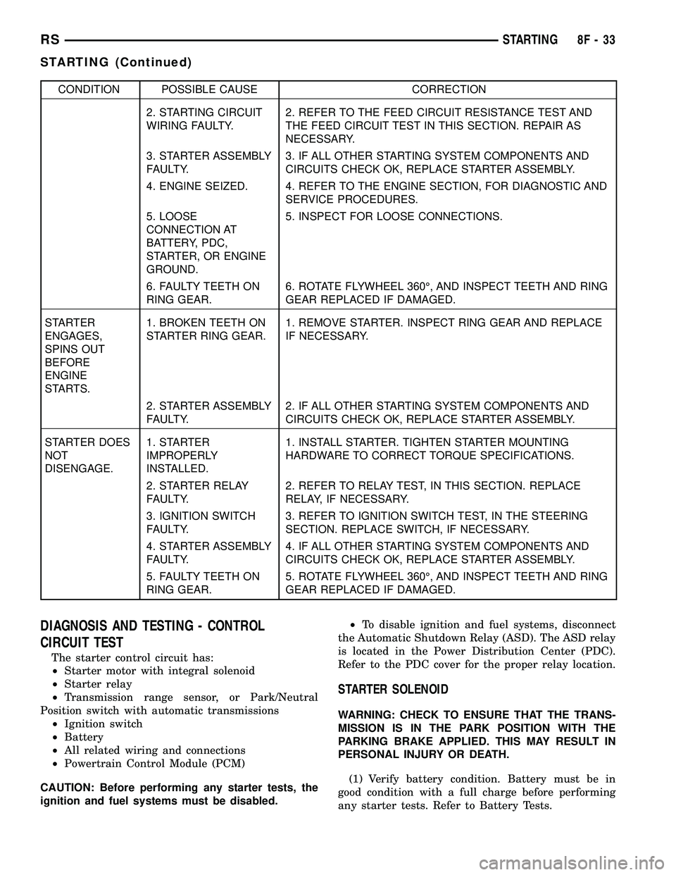
CONDITION POSSIBLE CAUSE CORRECTION
2. STARTING CIRCUIT
WIRING FAULTY.2. REFER TO THE FEED CIRCUIT RESISTANCE TEST AND
THE FEED CIRCUIT TEST IN THIS SECTION. REPAIR AS
NECESSARY.
3. STARTER ASSEMBLY
FAULTY.3. IF ALL OTHER STARTING SYSTEM COMPONENTS AND
CIRCUITS CHECK OK, REPLACE STARTER ASSEMBLY.
4. ENGINE SEIZED. 4. REFER TO THE ENGINE SECTION, FOR DIAGNOSTIC AND
SERVICE PROCEDURES.
5. LOOSE
CONNECTION AT
BATTERY, PDC,
STARTER, OR ENGINE
GROUND.5. INSPECT FOR LOOSE CONNECTIONS.
6. FAULTY TEETH ON
RING GEAR.6. ROTATE FLYWHEEL 360É, AND INSPECT TEETH AND RING
GEAR REPLACED IF DAMAGED.
STARTER
ENGAGES,
SPINS OUT
BEFORE
ENGINE
STARTS.1. BROKEN TEETH ON
STARTER RING GEAR.1. REMOVE STARTER. INSPECT RING GEAR AND REPLACE
IF NECESSARY.
2. STARTER ASSEMBLY
FAULTY.2. IF ALL OTHER STARTING SYSTEM COMPONENTS AND
CIRCUITS CHECK OK, REPLACE STARTER ASSEMBLY.
STARTER DOES
NOT
DISENGAGE.1. STARTER
IMPROPERLY
INSTALLED.1. INSTALL STARTER. TIGHTEN STARTER MOUNTING
HARDWARE TO CORRECT TORQUE SPECIFICATIONS.
2. STARTER RELAY
FAULTY.2. REFER TO RELAY TEST, IN THIS SECTION. REPLACE
RELAY, IF NECESSARY.
3. IGNITION SWITCH
FAULTY.3. REFER TO IGNITION SWITCH TEST, IN THE STEERING
SECTION. REPLACE SWITCH, IF NECESSARY.
4. STARTER ASSEMBLY
FAULTY.4. IF ALL OTHER STARTING SYSTEM COMPONENTS AND
CIRCUITS CHECK OK, REPLACE STARTER ASSEMBLY.
5. FAULTY TEETH ON
RING GEAR.5. ROTATE FLYWHEEL 360É, AND INSPECT TEETH AND RING
GEAR REPLACED IF DAMAGED.
DIAGNOSIS AND TESTING - CONTROL
CIRCUIT TEST
The starter control circuit has:
²Starter motor with integral solenoid
²Starter relay
²Transmission range sensor, or Park/Neutral
Position switch with automatic transmissions
²Ignition switch
²Battery
²All related wiring and connections
²Powertrain Control Module (PCM)
CAUTION: Before performing any starter tests, the
ignition and fuel systems must be disabled.²To disable ignition and fuel systems, disconnect
the Automatic Shutdown Relay (ASD). The ASD relay
is located in the Power Distribution Center (PDC).
Refer to the PDC cover for the proper relay location.
STARTER SOLENOID
WARNING: CHECK TO ENSURE THAT THE TRANS-
MISSION IS IN THE PARK POSITION WITH THE
PARKING BRAKE APPLIED. THIS MAY RESULT IN
PERSONAL INJURY OR DEATH.
(1) Verify battery condition. Battery must be in
good condition with a full charge before performing
any starter tests. Refer to Battery Tests.
RSSTARTING8F-33
STARTING (Continued)