timing belt CHRYSLER CARAVAN 2005 Service Manual
[x] Cancel search | Manufacturer: CHRYSLER, Model Year: 2005, Model line: CARAVAN, Model: CHRYSLER CARAVAN 2005Pages: 2339, PDF Size: 59.69 MB
Page 28 of 2339
![CHRYSLER CARAVAN 2005 Service Manual Kilometers 156 000 160 000 168 000 180 000 192 000
(Miles) (97,500) (100,000) (105,000) (112,500) (120,000)
[Months] [78] [84] [90] [96]
Inspect the tie rod ends and boot seals. X
Inspect and adjust t CHRYSLER CARAVAN 2005 Service Manual Kilometers 156 000 160 000 168 000 180 000 192 000
(Miles) (97,500) (100,000) (105,000) (112,500) (120,000)
[Months] [78] [84] [90] [96]
Inspect the tie rod ends and boot seals. X
Inspect and adjust t](/img/25/56862/w960_56862-27.png)
Kilometers 156 000 160 000 168 000 180 000 192 000
(Miles) (97,500) (100,000) (105,000) (112,500) (120,000)
[Months] [78] [84] [90] [96]
Inspect the tie rod ends and boot seals. X
Inspect and adjust the power steering pump
belt tension on 2.4 liter engines.XX
Inspect the generator belt on 2.4 liter
engines, replace if necessary.XX
Check and replace thePCV valve,if
necessary.*X
Inspect the serpentine drive belt on 3.3 liter
engines, replace if necessary. ³XX
Replace thespark plugs3.3 liter engines. X
Replace theignition cables3.3 liter
engines.X
Flush and replace the engine coolant at
100,000 miles, if not done at 60 months.X
Replace theengine timing belton 2.4 liter
engines only.X
Replace the air conditioning filter. X
* This maintenance is recommended by the manu-
facture to the owner but is not required to maintain
the emissions warranty.
³ This maintenance is not required if previously
replaced.Inspection and service should also be performed
anytime a malfunction is observed or suspected.
Retain all receipts.
RSLUBRICATION & MAINTENANCE0-15
MAINTENANCE SCHEDULES (Continued)
Page 32 of 2339
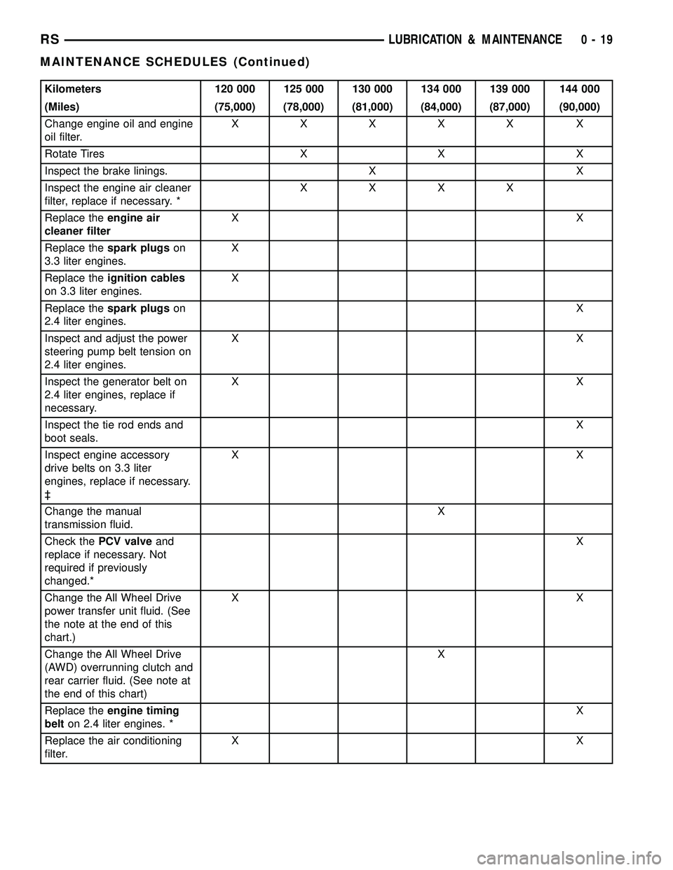
Kilometers 120 000 125 000 130 000 134 000 139 000 144 000
(Miles) (75,000) (78,000) (81,000) (84,000) (87,000) (90,000)
Change engine oil and engine
oil filter.XXXXX X
Rotate Tires X X X
Inspect the brake linings. X X
Inspect the engine air cleaner
filter, replace if necessary. *XXXX
Replace theengine air
cleaner filterXX
Replace thespark plugson
3.3 liter engines.X
Replace theignition cables
on 3.3 liter engines.X
Replace thespark plugson
2.4 liter engines.X
Inspect and adjust the power
steering pump belt tension on
2.4 liter engines.XX
Inspect the generator belt on
2.4 liter engines, replace if
necessary.XX
Inspect the tie rod ends and
boot seals.X
Inspect engine accessory
drive belts on 3.3 liter
engines, replace if necessary.
³XX
Change the manual
transmission fluid.X
Check thePCV valveand
replace if necessary. Not
required if previously
changed.*X
Change the All Wheel Drive
power transfer unit fluid. (See
the note at the end of this
chart.)XX
Change the All Wheel Drive
(AWD) overrunning clutch and
rear carrier fluid. (See note at
the end of this chart)X
Replace theengine timing
belton 2.4 liter engines. *X
Replace the air conditioning
filter.XX
RSLUBRICATION & MAINTENANCE0-19
MAINTENANCE SCHEDULES (Continued)
Page 35 of 2339
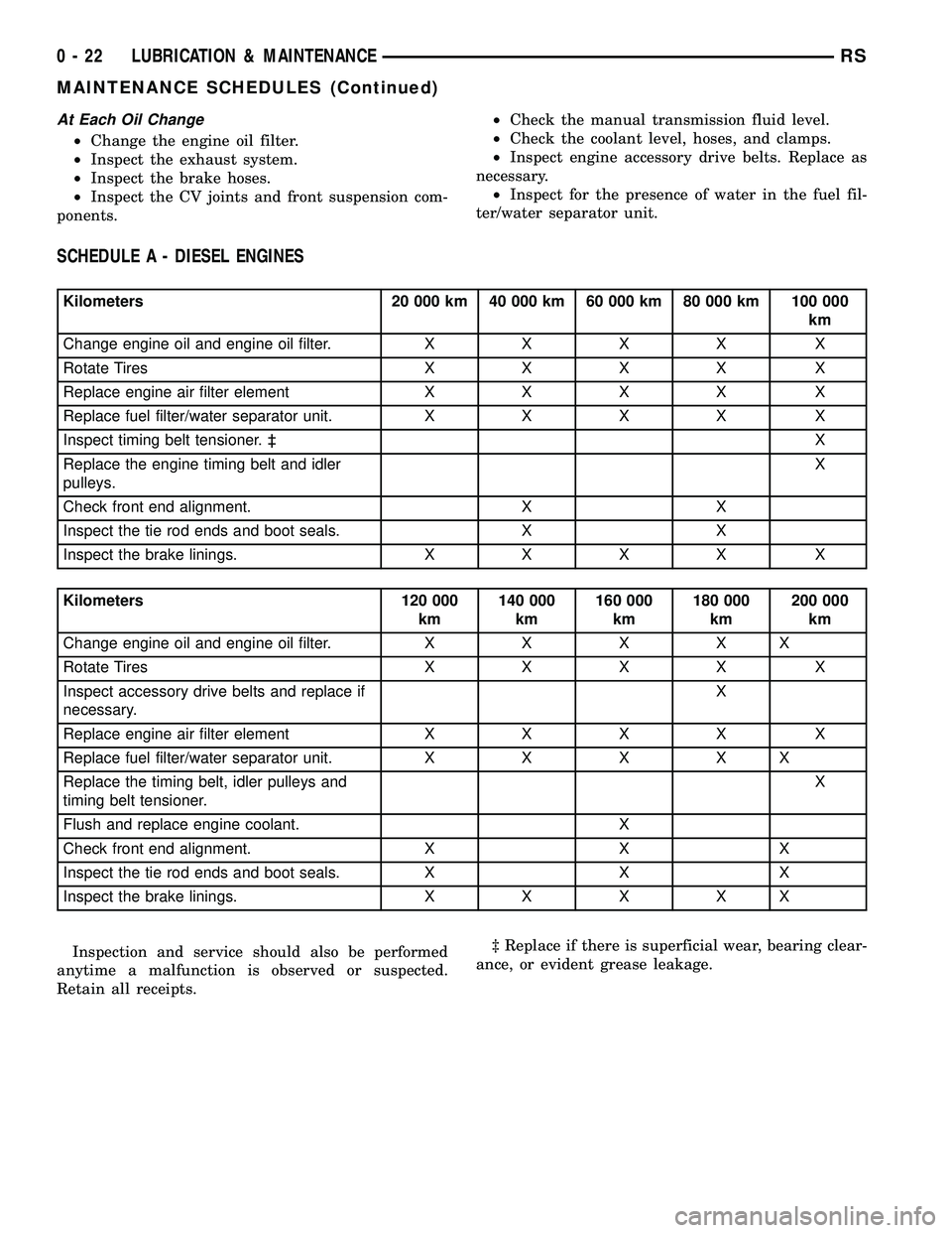
At Each Oil Change
²Change the engine oil filter.
²Inspect the exhaust system.
²Inspect the brake hoses.
²Inspect the CV joints and front suspension com-
ponents.²Check the manual transmission fluid level.
²Check the coolant level, hoses, and clamps.
²Inspect engine accessory drive belts. Replace as
necessary.
²Inspect for the presence of water in the fuel fil-
ter/water separator unit.
SCHEDULE A - DIESEL ENGINES
Kilometers 20 000 km 40 000 km 60 000 km 80 000 km 100 000
km
Change engine oil and engine oil filter.XXXX X
Rotate TiresXXXX X
Replace engine air filter elementXXXX X
Replace fuel filter/water separator unit.XXXX X
Inspect timing belt tensioner. ³X
Replace the engine timing belt and idler
pulleys.X
Check front end alignment. X X
Inspect the tie rod ends and boot seals. X X
Inspect the brake linings.XXXX X
Kilometers 120 000
km140 000
km160 000
km180 000
km200 000
km
Change engine oil and engine oil filter.XXXXX
Rotate TiresXXXX X
Inspect accessory drive belts and replace if
necessary.X
Replace engine air filter elementXXXX X
Replace fuel filter/water separator unit.XXXXX
Replace the timing belt, idler pulleys and
timing belt tensioner.X
Flush and replace engine coolant. X
Check front end alignment. X X X
Inspect the tie rod ends and boot seals. X X X
Inspect the brake linings.XXXXX
Inspection and service should also be performed
anytime a malfunction is observed or suspected.
Retain all receipts.³ Replace if there is superficial wear, bearing clear-
ance, or evident grease leakage.
0 - 22 LUBRICATION & MAINTENANCERS
MAINTENANCE SCHEDULES (Continued)
Page 36 of 2339
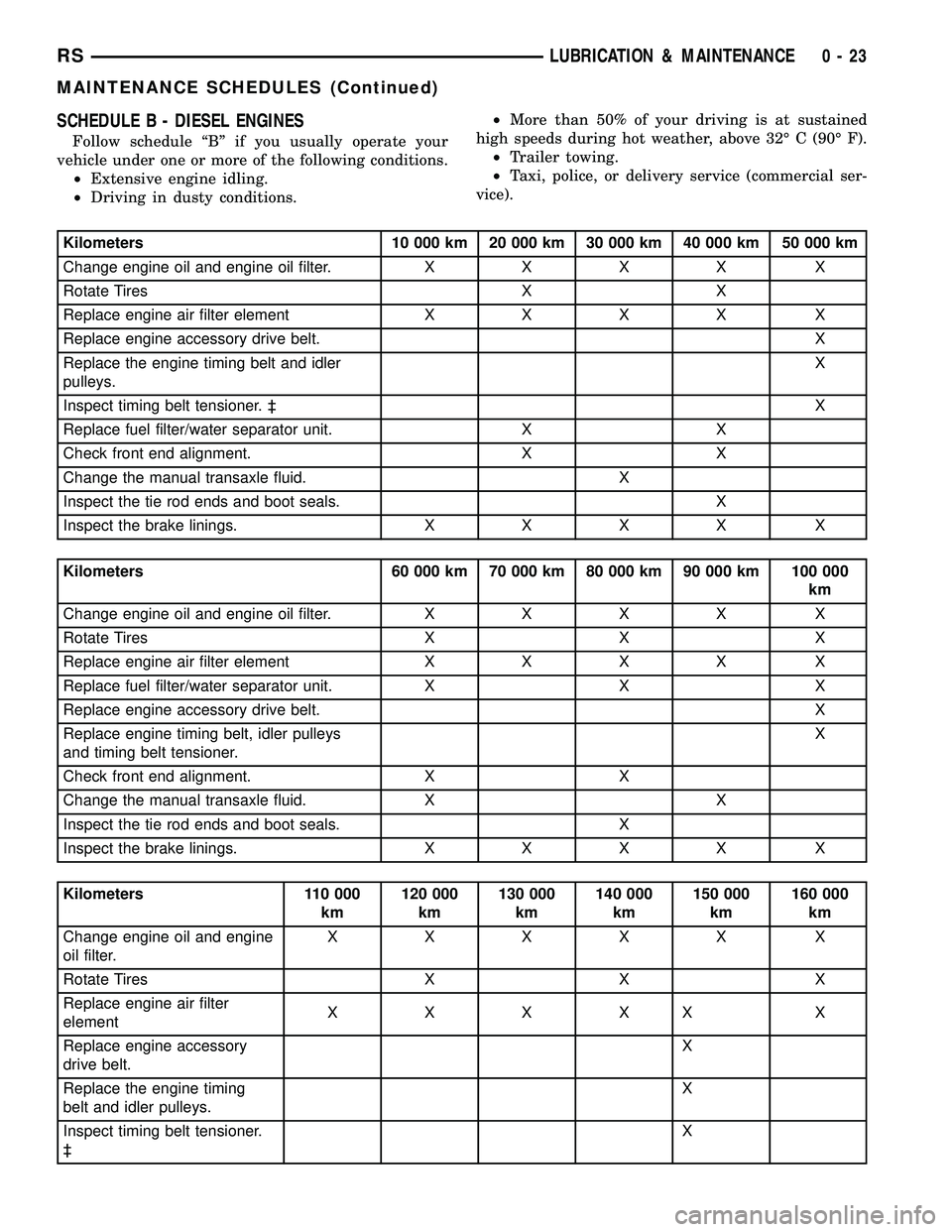
SCHEDULE B - DIESEL ENGINES
Follow schedule ªBº if you usually operate your
vehicle under one or more of the following conditions.
²Extensive engine idling.
²Driving in dusty conditions.²More than 50% of your driving is at sustained
high speeds during hot weather, above 32É C (90É F).
²Trailer towing.
²Taxi, police, or delivery service (commercial ser-
vice).
Kilometers 10 000 km 20 000 km 30 000 km 40 000 km 50 000 km
Change engine oil and engine oil filter.XXXX X
Rotate Tires X X
Replace engine air filter elementXXXX X
Replace engine accessory drive belt. X
Replace the engine timing belt and idler
pulleys.X
Inspect timing belt tensioner. ³X
Replace fuel filter/water separator unit. X X
Check front end alignment. X X
Change the manual transaxle fluid. X
Inspect the tie rod ends and boot seals. X
Inspect the brake linings.XXXX X
Kilometers 60 000 km 70 000 km 80 000 km 90 000 km 100 000
km
Change engine oil and engine oil filter.XXXX X
Rotate Tires X X X
Replace engine air filter elementXXXX X
Replace fuel filter/water separator unit. X X X
Replace engine accessory drive belt. X
Replace engine timing belt, idler pulleys
and timing belt tensioner.X
Check front end alignment. X X
Change the manual transaxle fluid. X X
Inspect the tie rod ends and boot seals. X
Inspect the brake linings.XXXX X
Kilometers 110 000
km120 000
km130 000
km140 000
km150 000
km160 000
km
Change engine oil and engine
oil filter.XXXXX X
Rotate Tires X X X
Replace engine air filter
elementXXXXX X
Replace engine accessory
drive belt.X
Replace the engine timing
belt and idler pulleys.X
Inspect timing belt tensioner.
³X
RSLUBRICATION & MAINTENANCE0-23
MAINTENANCE SCHEDULES (Continued)
Page 251 of 2339
WATER PUMP - 2.4L
DESCRIPTION
The water pump has a cast aluminum body and
housing with a stamped steel impeller. The water
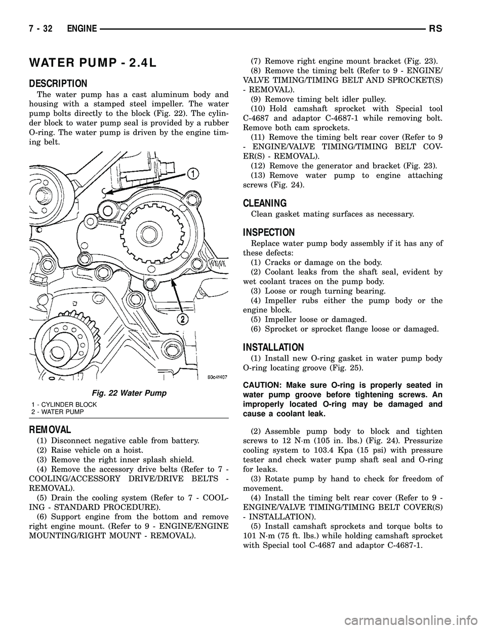
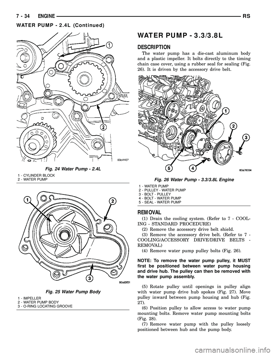
pump bolts directly to the block (Fig. 22). The cylin-
der block to water pump seal is provided by a rubber
O-ring. The water pump is driven by the engine tim-
ing belt.
REMOVAL
(1) Disconnect negative cable from battery.
(2) Raise vehicle on a hoist.
(3) Remove the right inner splash shield.
(4) Remove the accessory drive belts (Refer to 7 -
COOLING/ACCESSORY DRIVE/DRIVE BELTS -
REMOVAL).
(5) Drain the cooling system (Refer to 7 - COOL-
ING - STANDARD PROCEDURE).
(6) Support engine from the bottom and remove
right engine mount. (Refer to 9 - ENGINE/ENGINE
MOUNTING/RIGHT MOUNT - REMOVAL).(7) Remove right engine mount bracket (Fig. 23).
(8) Remove the timing belt (Refer to 9 - ENGINE/
VALVE TIMING/TIMING BELT AND SPROCKET(S)
- REMOVAL).
(9) Remove timing belt idler pulley.
(10) Hold camshaft sprocket with Special tool
C-4687 and adaptor C-4687-1 while removing bolt.
Remove both cam sprockets.
(11) Remove the timing belt rear cover (Refer to 9
- ENGINE/VALVE TIMING/TIMING BELT COV-
ER(S) - REMOVAL).
(12) Remove the generator and bracket (Fig. 23).
(13) Remove water pump to engine attaching
screws (Fig. 24).
CLEANING
Clean gasket mating surfaces as necessary.
INSPECTION
Replace water pump body assembly if it has any of
these defects:
(1) Cracks or damage on the body.
(2) Coolant leaks from the shaft seal, evident by
wet coolant traces on the pump body.
(3) Loose or rough turning bearing.
(4) Impeller rubs either the pump body or the
engine block.
(5) Impeller loose or damaged.
(6) Sprocket or sprocket flange loose or damaged.
INSTALLATION
(1) Install new O-ring gasket in water pump body
O-ring locating groove (Fig. 25).
CAUTION: Make sure O-ring is properly seated in
water pump groove before tightening screws. An
improperly located O-ring may be damaged and
cause a coolant leak.
(2) Assemble pump body to block and tighten
screws to 12 N´m (105 in. lbs.) (Fig. 24). Pressurize
cooling system to 103.4 Kpa (15 psi) with pressure
tester and check water pump shaft seal and O-ring
for leaks.
(3) Rotate pump by hand to check for freedom of
movement.
(4) Install the timing belt rear cover (Refer to 9 -
ENGINE/VALVE TIMING/TIMING BELT COVER(S)
- INSTALLATION).
(5) Install camshaft sprockets and torque bolts to
101 N´m (75 ft. lbs.) while holding camshaft sprocket
with Special tool C-4687 and adaptor C-4687-1.
Fig. 22 Water Pump
1 - CYLINDER BLOCK
2 - WATER PUMP
7 - 32 ENGINERS
Page 252 of 2339
(6) Install timing belt idler pulley and torque
mounting bolt to 61 N´m (45 ft. lbs.).
(7) Install the timing belt (Refer to 9 - ENGINE/
VALVE TIMING/TIMING BELT AND SPROCKET(S)
- INSTALLATION).
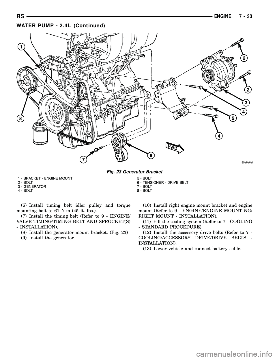
(8) Install the generator mount bracket. (Fig. 23)
(9) Install the generator.(10) Install right engine mount bracket and engine
mount (Refer to 9 - ENGINE/ENGINE MOUNTING/
RIGHT MOUNT - INSTALLATION).
(11) Fill the cooling system (Refer to 7 - COOLING
- STANDARD PROCEDURE).
(12) Install the accessory drive belts (Refer to 7 -
COOLING/ACCESSORY DRIVE/DRIVE BELTS -
INSTALLATION).
(13) Lower vehicle and connect battery cable.
Fig. 23 Generator Bracket
1 - BRACKET - ENGINE MOUNT 5 - BOLT
2 - BOLT 6 - TENSIONER - DRIVE BELT
3 - GENERATOR 7 - BOLT
4 - BOLT 8 - BOLT
RSENGINE7-33
WATER PUMP - 2.4L (Continued)
Page 253 of 2339
WATER PUMP - 3.3/3.8L
DESCRIPTION
The water pump has a die-cast aluminum body
and a plastic impeller. It bolts directly to the timing
chain case cover, using a rubber seal for sealing (Fig.
26). It is driven by the accessory drive belt.
REMOVAL
(1) Drain the cooling system. (Refer to 7 - COOL-
ING - STANDARD PROCEDURE)
(2) Remove the accessory drive belt shield.
(3) Remove the accessory drive belt. (Refer to 7 -
COOLING/ACCESSORY DRIVE/DRIVE BELTS -
REMOVAL)
(4) Remove water pump pulley bolts (Fig. 26).
NOTE: To remove the water pump pulley, it MUST
first be positioned between water pump housing
and drive hub. The pulley can then be removed with
the water pump assembly.
(5) Rotate pulley until openings in pulley align
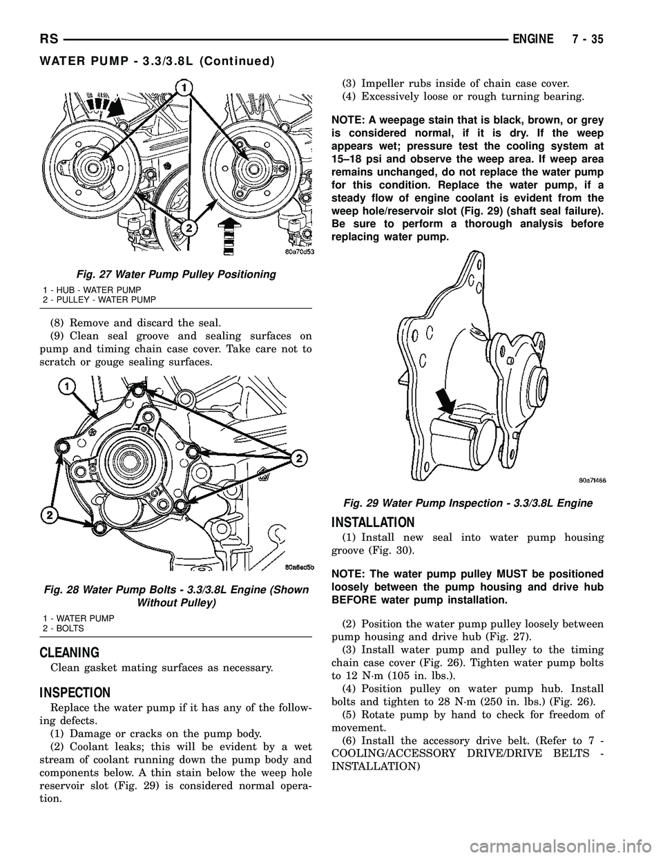
with water pump drive hub spokes (Fig. 27). Move
pulley inward between pump housing and hub (Fig.
27).
(6) Position pulley to allow access to water pump
mounting bolts. Remove water pump mounting bolts
(Fig. 28).
(7) Remove water pump with the pulley loosely
positioned between hub and the pump body.
Fig. 24 Water Pump - 2.4L
1 - CYLINDER BLOCK
2 - WATER PUMP
Fig. 25 Water Pump Body
1 - IMPELLER
2 - WATER PUMP BODY
3 - O-RING LOCATING GROOVE
Fig. 26 Water Pump - 3.3/3.8L Engine
1 - WATER PUMP
2 - PULLEY - WATER PUMP
3 - BOLT - PULLEY
4 - BOLT - WATER PUMP
5 - SEAL - WATER PUMP
7 - 34 ENGINERS
WATER PUMP - 2.4L (Continued)
Page 254 of 2339
(8) Remove and discard the seal.
(9) Clean seal groove and sealing surfaces on
pump and timing chain case cover. Take care not to
scratch or gouge sealing surfaces.
CLEANING
Clean gasket mating surfaces as necessary.
INSPECTION
Replace the water pump if it has any of the follow-
ing defects.
(1) Damage or cracks on the pump body.
(2) Coolant leaks; this will be evident by a wet
stream of coolant running down the pump body and
components below. A thin stain below the weep hole
reservoir slot (Fig. 29) is considered normal opera-
tion.(3) Impeller rubs inside of chain case cover.
(4) Excessively loose or rough turning bearing.
NOTE: A weepage stain that is black, brown, or grey
is considered normal, if it is dry. If the weep
appears wet; pressure test the cooling system at
15±18 psi and observe the weep area. If weep area
remains unchanged, do not replace the water pump
for this condition. Replace the water pump, if a
steady flow of engine coolant is evident from the
weep hole/reservoir slot (Fig. 29) (shaft seal failure).
Be sure to perform a thorough analysis before
replacing water pump.
INSTALLATION
(1) Install new seal into water pump housing
groove (Fig. 30).
NOTE: The water pump pulley MUST be positioned
loosely between the pump housing and drive hub
BEFORE water pump installation.
(2) Position the water pump pulley loosely between
pump housing and drive hub (Fig. 27).
(3) Install water pump and pulley to the timing
chain case cover (Fig. 26). Tighten water pump bolts
to 12 N´m (105 in. lbs.).
(4) Position pulley on water pump hub. Install
bolts and tighten to 28 N´m (250 in. lbs.) (Fig. 26).
(5) Rotate pump by hand to check for freedom of
movement.
(6) Install the accessory drive belt. (Refer to 7 -
COOLING/ACCESSORY DRIVE/DRIVE BELTS -
INSTALLATION)
Fig. 27 Water Pump Pulley Positioning
1 - HUB - WATER PUMP
2 - PULLEY - WATER PUMP
Fig. 28 Water Pump Bolts - 3.3/3.8L Engine (Shown
Without Pulley)
1 - WATER PUMP
2 - BOLTS
Fig. 29 Water Pump Inspection - 3.3/3.8L Engine
RSENGINE7-35
WATER PUMP - 3.3/3.8L (Continued)
Page 256 of 2339
WATER PUMP INLET TUBE -
3.3/3.8L
REMOVAL
(1) Drain the cooling system. (Refer to 7 - COOL-
ING - STANDARD PROCEDURE)
(2) Raise vehicle on hoist and remove the belt
splash shield.
(3) Remove the radiator lower hose from inlet tube
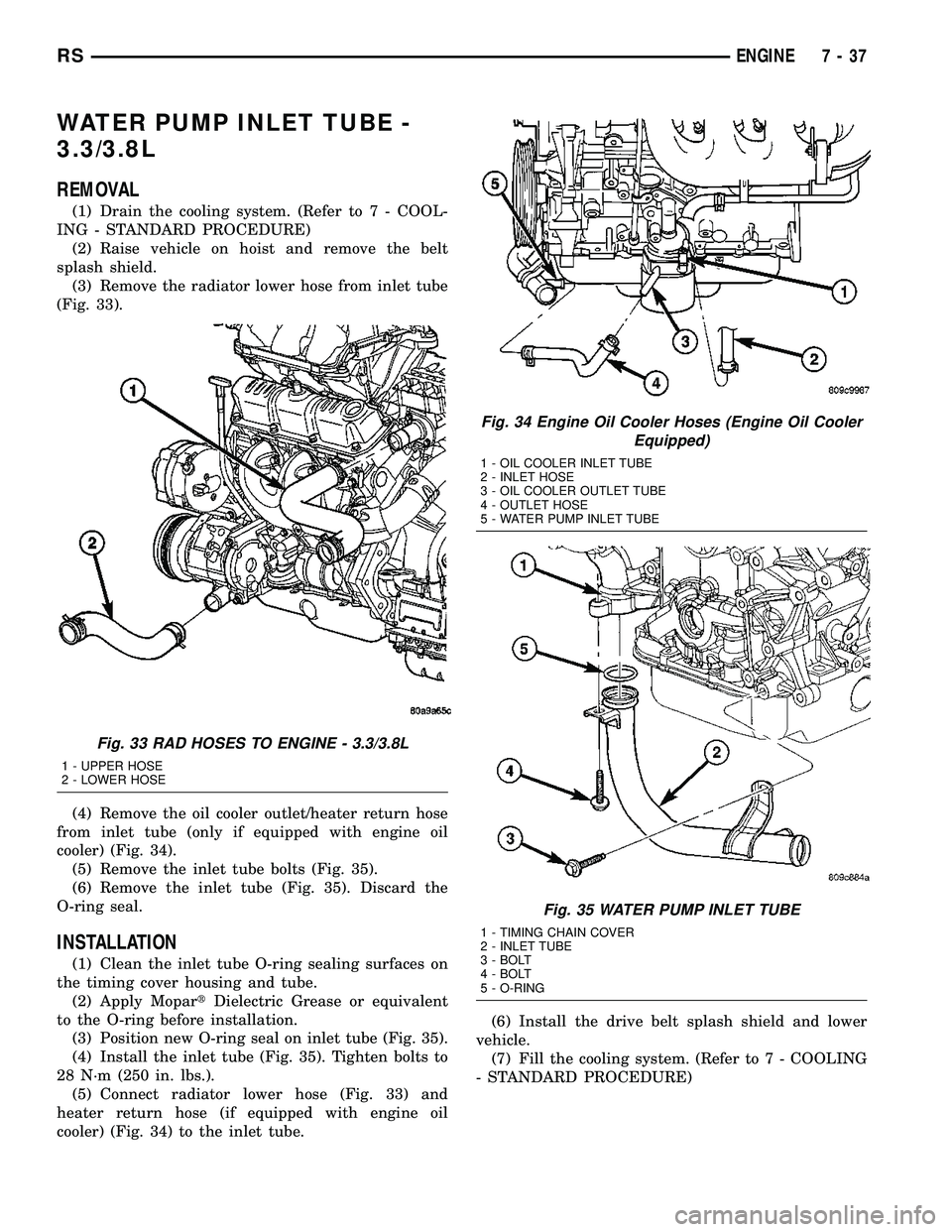
(Fig. 33).
(4) Remove the oil cooler outlet/heater return hose
from inlet tube (only if equipped with engine oil
cooler) (Fig. 34).
(5) Remove the inlet tube bolts (Fig. 35).
(6) Remove the inlet tube (Fig. 35). Discard the
O-ring seal.
INSTALLATION
(1) Clean the inlet tube O-ring sealing surfaces on
the timing cover housing and tube.
(2) Apply MopartDielectric Grease or equivalent
to the O-ring before installation.
(3) Position new O-ring seal on inlet tube (Fig. 35).
(4) Install the inlet tube (Fig. 35). Tighten bolts to
28 N´m (250 in. lbs.).
(5) Connect radiator lower hose (Fig. 33) and
heater return hose (if equipped with engine oil
cooler) (Fig. 34) to the inlet tube.(6) Install the drive belt splash shield and lower
vehicle.
(7) Fill the cooling system. (Refer to 7 - COOLING
- STANDARD PROCEDURE)
Fig. 33 RAD HOSES TO ENGINE - 3.3/3.8L
1 - UPPER HOSE
2 - LOWER HOSE
Fig. 34 Engine Oil Cooler Hoses (Engine Oil Cooler
Equipped)
1 - OIL COOLER INLET TUBE
2 - INLET HOSE
3 - OIL COOLER OUTLET TUBE
4 - OUTLET HOSE
5 - WATER PUMP INLET TUBE
Fig. 35 WATER PUMP INLET TUBE
1 - TIMING CHAIN COVER
2 - INLET TUBE
3 - BOLT
4 - BOLT
5 - O-RING
RSENGINE7-37
Page 1179 of 2339
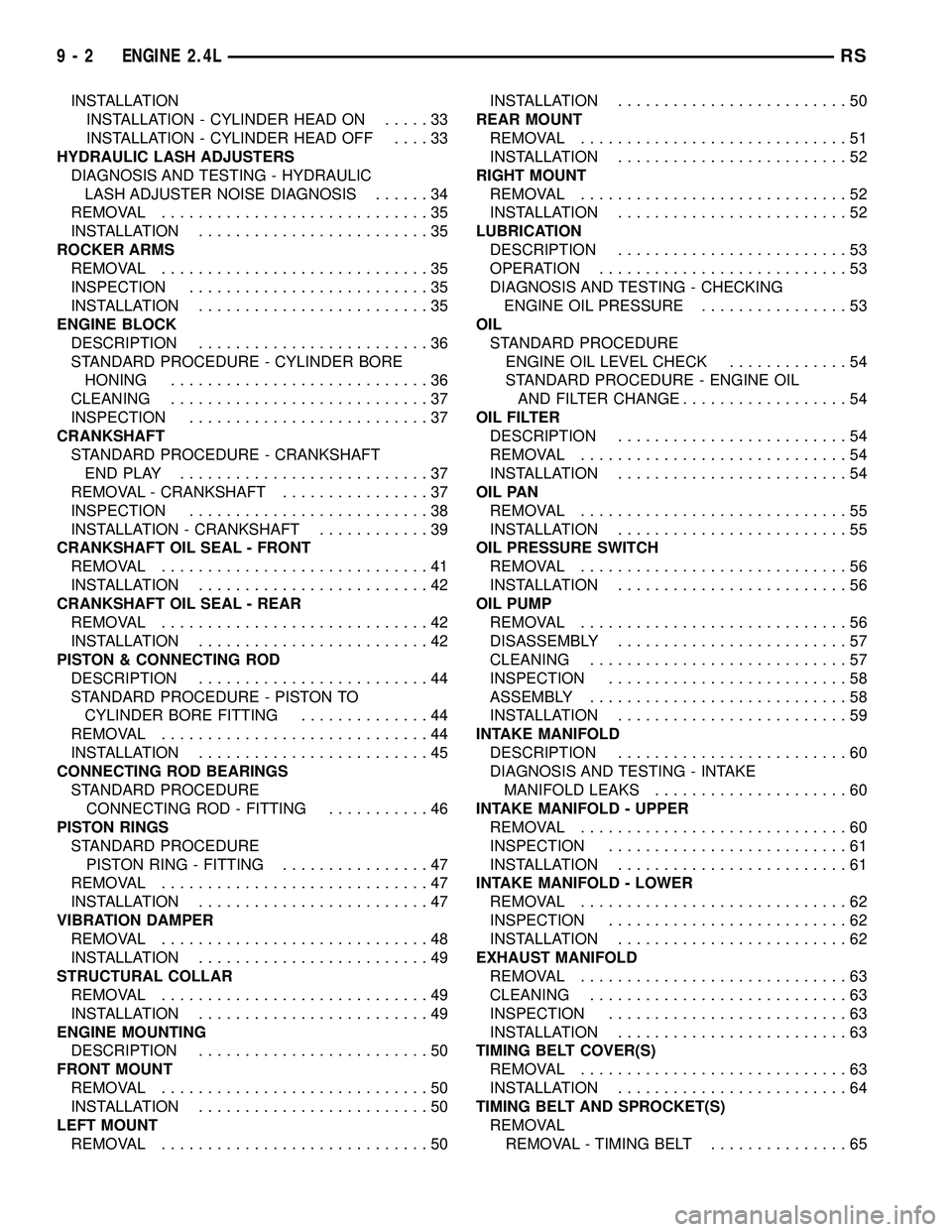
INSTALLATION
INSTALLATION - CYLINDER HEAD ON.....33
INSTALLATION - CYLINDER HEAD OFF....33
HYDRAULIC LASH ADJUSTERS
DIAGNOSIS AND TESTING - HYDRAULIC
LASH ADJUSTER NOISE DIAGNOSIS......34
REMOVAL.............................35
INSTALLATION.........................35
ROCKER ARMS
REMOVAL.............................35
INSPECTION..........................35
INSTALLATION.........................35
ENGINE BLOCK
DESCRIPTION.........................36
STANDARD PROCEDURE - CYLINDER BORE
HONING............................36
CLEANING............................37
INSPECTION..........................37
CRANKSHAFT
STANDARD PROCEDURE - CRANKSHAFT
ENDPLAY ...........................37
REMOVAL - CRANKSHAFT................37
INSPECTION..........................38
INSTALLATION - CRANKSHAFT............39
CRANKSHAFT OIL SEAL - FRONT
REMOVAL.............................41
INSTALLATION.........................42
CRANKSHAFT OIL SEAL - REAR
REMOVAL.............................42
INSTALLATION.........................42
PISTON & CONNECTING ROD
DESCRIPTION.........................44
STANDARD PROCEDURE - PISTON TO
CYLINDER BORE FITTING..............44
REMOVAL.............................44
INSTALLATION.........................45
CONNECTING ROD BEARINGS
STANDARD PROCEDURE
CONNECTING ROD - FITTING...........46
PISTON RINGS
STANDARD PROCEDURE
PISTON RING - FITTING................47
REMOVAL.............................47
INSTALLATION.........................47
VIBRATION DAMPER
REMOVAL.............................48
INSTALLATION.........................49
STRUCTURAL COLLAR
REMOVAL.............................49
INSTALLATION.........................49
ENGINE MOUNTING
DESCRIPTION.........................50
FRONT MOUNT
REMOVAL.............................50
INSTALLATION.........................50
LEFT MOUNT
REMOVAL.............................50INSTALLATION.........................50
REAR MOUNT
REMOVAL.............................51
INSTALLATION.........................52
RIGHT MOUNT
REMOVAL.............................52
INSTALLATION.........................52
LUBRICATION
DESCRIPTION.........................53
OPERATION...........................53
DIAGNOSIS AND TESTING - CHECKING
ENGINE OIL PRESSURE................53
OIL
STANDARD PROCEDURE
ENGINE OIL LEVEL CHECK.............54
STANDARD PROCEDURE - ENGINE OIL
AND FILTER CHANGE..................54
OIL FILTER
DESCRIPTION.........................54
REMOVAL.............................54
INSTALLATION.........................54
OIL PAN
REMOVAL.............................55
INSTALLATION.........................55
OIL PRESSURE SWITCH
REMOVAL.............................56
INSTALLATION.........................56
OIL PUMP
REMOVAL.............................56
DISASSEMBLY.........................57
CLEANING............................57
INSPECTION..........................58
ASSEMBLY............................58
INSTALLATION.........................59
INTAKE MANIFOLD
DESCRIPTION.........................60
DIAGNOSIS AND TESTING - INTAKE
MANIFOLD LEAKS.....................60
INTAKE MANIFOLD - UPPER
REMOVAL.............................60
INSPECTION..........................61
INSTALLATION.........................61
INTAKE MANIFOLD - LOWER
REMOVAL.............................62
INSPECTION..........................62
INSTALLATION.........................62
EXHAUST MANIFOLD
REMOVAL.............................63
CLEANING............................63
INSPECTION..........................63
INSTALLATION.........................63
TIMING BELT COVER(S)
REMOVAL.............................63
INSTALLATION.........................64
TIMING BELT AND SPROCKET(S)
REMOVAL
REMOVAL - TIMING BELT...............65
9 - 2 ENGINE 2.4LRS