clock CHRYSLER VOYAGER 1996 Owners Manual
[x] Cancel search | Manufacturer: CHRYSLER, Model Year: 1996, Model line: VOYAGER, Model: CHRYSLER VOYAGER 1996Pages: 1938, PDF Size: 55.84 MB
Page 1389 of 1938
three injection pump mounting flanges while
gear is being removed.
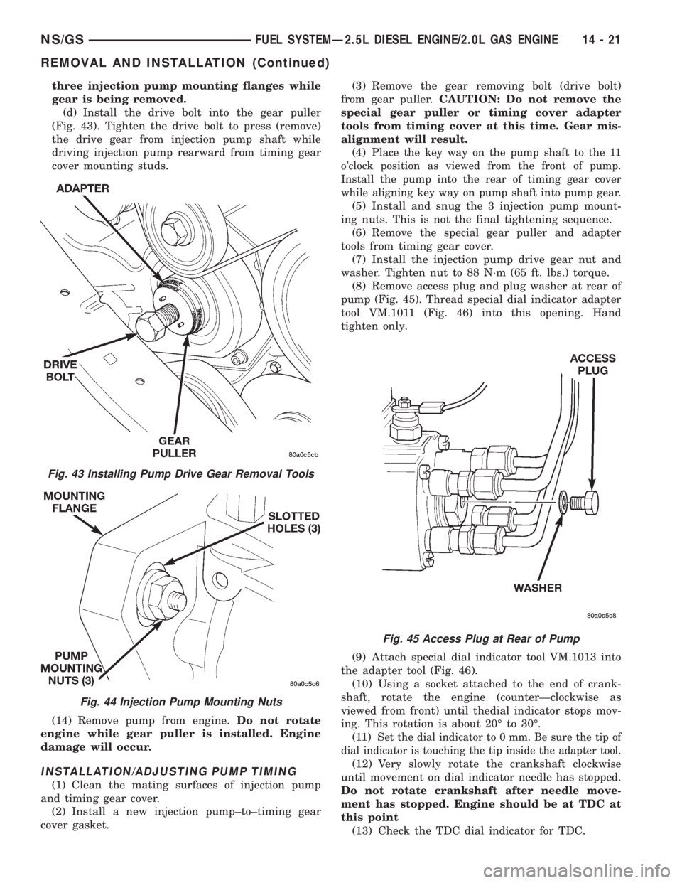
(d) Install the drive bolt into the gear puller
(Fig. 43). Tighten the drive bolt to press (remove)
the drive gear from injection pump shaft while
driving injection pump rearward from timing gear
cover mounting studs.
(14) Remove pump from engine.Do not rotate
engine while gear puller is installed. Engine
damage will occur.
INSTALLATION/ADJUSTING PUMP TIMING
(1) Clean the mating surfaces of injection pump
and timing gear cover.
(2) Install a new injection pump±to±timing gear
cover gasket.(3) Remove the gear removing bolt (drive bolt)
from gear puller.CAUTION: Do not remove the
special gear puller or timing cover adapter
tools from timing cover at this time. Gear mis-
alignment will result.
(4) P
lace the key way on the pump shaft to the 11
o'clock position as viewed from the front of pump.
Install the pump into the rear of timing gear cover
while aligning key way on pump shaft into pump gear.
(5) Install and snug the 3 injection pump mount-
ing nuts. This is not the final tightening sequence.
(6) Remove the special gear puller and adapter
tools from timing gear cover.
(7) Install the injection pump drive gear nut and
washer. Tighten nut to 88 N´m (65 ft. lbs.) torque.
(8) Remove access plug and plug washer at rear of
pump (Fig. 45). Thread special dial indicator adapter
tool VM.1011 (Fig. 46) into this opening. Hand
tighten only.
(9) Attach special dial indicator tool VM.1013 into
the adapter tool (Fig. 46).
(10) Using a socket attached to the end of crank-
shaft, rotate the engine (counterÐclockwise as
viewed from front) until thedial indicator stops mov-
ing. This rotation is about 20É to 30É.
(11) S
et the dial indicator to 0 mm. Be sure the tip of
dial indicator is touching the tip inside the adapter tool.
(12) Very slowly rotate the crankshaft clockwise
until movement on dial indicator needle has stopped.
Do not rotate crankshaft after needle move-
ment has stopped. Engine should be at TDC at
this point
(13) Check the TDC dial indicator for TDC.
Fig. 43 Installing Pump Drive Gear Removal Tools
Fig. 44 Injection Pump Mounting Nuts
Fig. 45 Access Plug at Rear of Pump
NS/GSFUEL SYSTEMÐ2.5L DIESEL ENGINE/2.0L GAS ENGINE 14 - 21
REMOVAL AND INSTALLATION (Continued)
Page 1390 of 1938

(14) Gauge reading should be at 0.60 mm. If not,
the pump must be rotated for adjustment:
(a) Loosen the three injection pump mounting
nuts at the mounting flanges. These flanges are
equipped with slotted holes. The slotted holes are
used to rotate and position the injection pump for
fuel timing. Loosen the three nuts just enough to
rotate the pump.
(b) Rotate the pumpclockwise(as viewed from
front) until .60 mm is indicated on the dial indica-
tor gauge.
(c) Tighten the three pump mounting nuts to 30
N´m (22 ft. lbs.) torque.
(d) Recheck the dial indicator after tightening
the pump mounting nuts. Gauge should still be
reading 0.60 mm. Loosen pump mounting nuts and
readjust if necessary.
(15) Remove dial indicator and adapter tools.
(16) Install access plug and washer to rear of
injection pump.
(17) Install plug at timing gear cover.
(18) Remove dial indicator from valve stem.
(19) Install valve spring and keepers.
(20) Install rocker arm assembly and tighten nuts.
(21) Install and connect the four high±pressure
fuel lines to the fuel injection pump. Also connect
fuel lines at the fuel injectors. For procedures, refer
to High±Pressure Fuel Lines in this group.
(22) Install electrical connector at engine coolant
temperature sensor.
(23) Connect electrical connector at fuel shutdown
solenoid.(24) Connect the main engine wiring harness to
the glow plugs.
(25) Connect the fuel timing solenoid pigtail har-
ness to the engine wiring harness.
(26) Connect the overflow valve/banjo fitting (fuel
return line assembly). Replace copper gaskets before
installing.
(27) Connect the rubber fuel return and supply
hoses to metal lines at pump. Tighten hose clamps to
2 N´m (20 in. lbs.) torque.
(28) Install generator assembly.
(29) Install engine accessory drive belt. Refer to
Group 7, Cooling System for procedures.
(30) Install negative battery cable to battery.
(31) Start the engine and bring to normal operat-
ing temperature.
(32) Check for fuel leaks.
FUEL INJECTORS
Four fuel injectors are used on each engine. Of these
four, two different types are used. The fuel injector used
on cylinder number one is equipped with a fuel injector
sensor (Fig. 47). The other three fuel injectors are iden-
tical.
Do not place the fuel injector equipped with
the fuel injector sensor into any other location
except the cylinder number one position.
REMOVAL
(1) Disconnect negative battery cable at battery.
(2) Thoroughly clean the area around the injector
with compressed air.
(3) Remove the fuel drain hoses (tubes) at each
injector (Fig. 48) being serviced. Each of these hoses
is slip±fit to the fitting on injector.
(4) Remove the high±pressure fuel line at injector
being removed. Refer to High±Pressure Fuel Lines in
this group for procedures.
(5) Remove the injector using special socket tool
number VM.1012A. When removing cylinder number
Fig. 46 Installing Dial Indicator and Special Adapter
Tools
Fig. 47 Fuel Injector SensorÐNumber±1 Cylinder
14 - 22 FUEL SYSTEMÐ2.5L DIESEL ENGINE/2.0L GAS ENGINENS/GS
REMOVAL AND INSTALLATION (Continued)
Page 1393 of 1938
fuel fitting. Refer to Tube/Fitting Assembly in the
Fuel Delivery section of this Group.
(7) Attach filler line to filler tube. Pull on connec-
tor to make sure of connection.
(8) Fill fuel tank, replace cap, and connect battery
negative cable.
FUEL RESERVOIR MODULE
REMOVAL
WARNING: THE FUEL RESERVOIR OF THE FUEL
MODULE DOES NOT EMPTY OUT WHEN THE TANK
IS DRAINED. THE FUEL IN THE RESERVOIR WILL
SPILL OUT WHEN THE MODULE IS REMOVED.
(1) Disconnect negative cable from battery.
(2) Insert fuel siphon hose into fuel filler neck and
push it into the tank.
(3) Drain fuel tank dry into holding tank or a
properly labeleddieselsafety container.
(4) Raise vehicle on hoist.
(5) Use a transmission jack to support the fuel
tank. Remove bolts from fuel tank straps. Lower
tank slightly.
(6) Clean area around fuel reservoir module and
tank to keep dirt and foreign material out of tank.
(7) Disconnect fuel lines from fuel module by
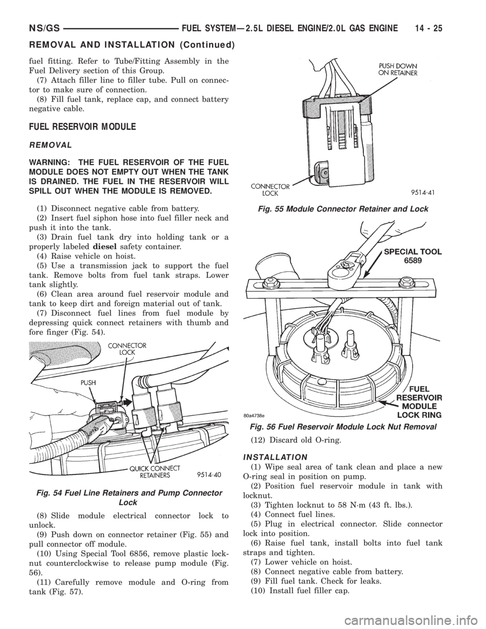
depressing quick connect retainers with thumb and
fore finger (Fig. 54).
(8) Slide module electrical connector lock to
unlock.
(9) Push down on connector retainer (Fig. 55) and
pull connector off module.
(10) Using Special Tool 6856, remove plastic lock-
nut counterclockwise to release pump module (Fig.
56).
(11) Carefully remove module and O-ring from
tank (Fig. 57).(12) Discard old O-ring.
INSTALLATION
(1) Wipe seal area of tank clean and place a new
O-ring seal in position on pump.
(2) Position fuel reservoir module in tank with
locknut.
(3) Tighten locknut to 58 N´m (43 ft. lbs.).
(4) Connect fuel lines.
(5) Plug in electrical connector. Slide connector
lock into position.
(6) Raise fuel tank, install bolts into fuel tank
straps and tighten.
(7) Lower vehicle on hoist.
(8) Connect negative cable from battery.
(9) Fill fuel tank. Check for leaks.
(10) Install fuel filler cap.
Fig. 54 Fuel Line Retainers and Pump Connector
Lock
Fig. 55 Module Connector Retainer and Lock
Fig. 56 Fuel Reservoir Module Lock Nut Removal
NS/GSFUEL SYSTEMÐ2.5L DIESEL ENGINE/2.0L GAS ENGINE 14 - 25
REMOVAL AND INSTALLATION (Continued)
Page 1429 of 1938
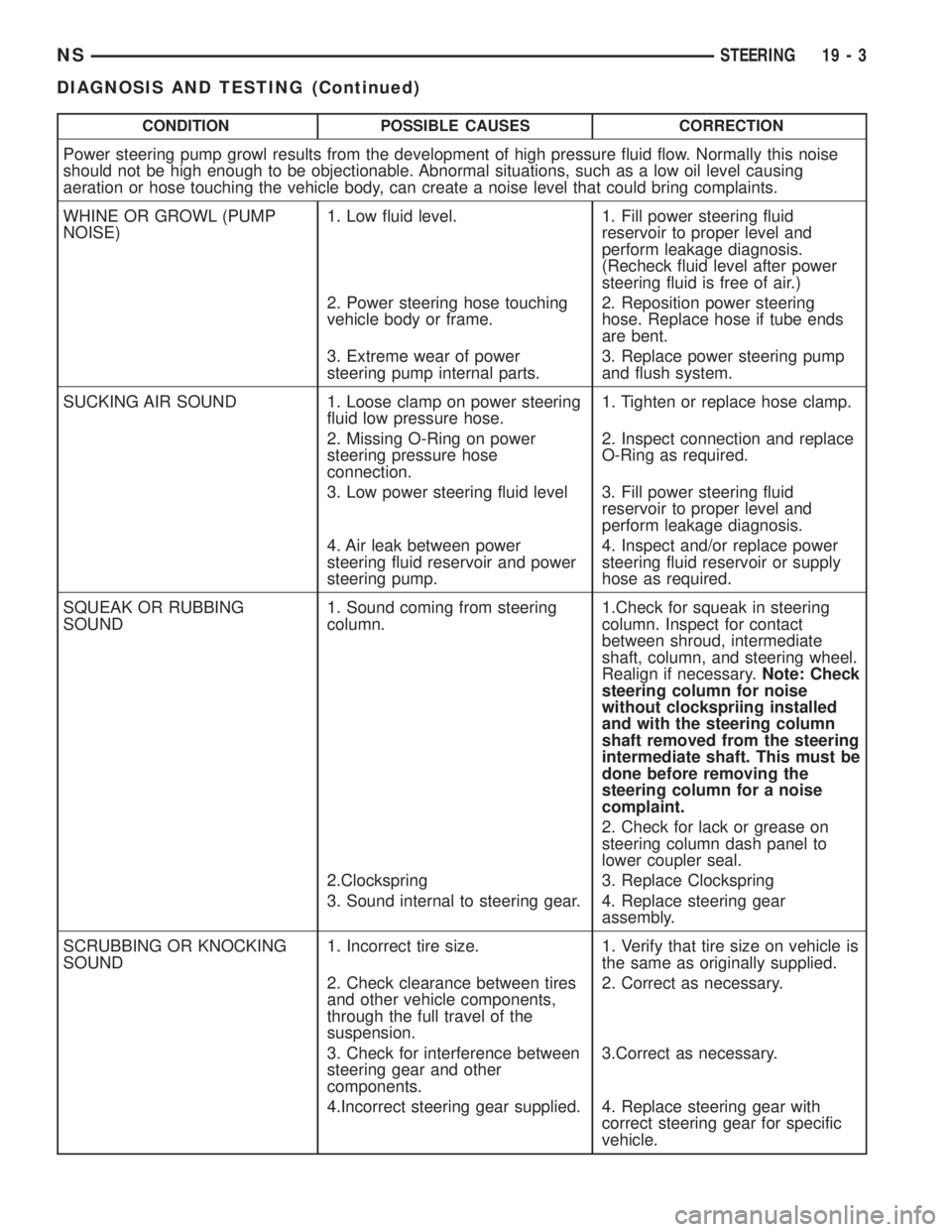
CONDITION POSSIBLE CAUSES CORRECTION
Power steering pump growl results from the development of high pressure fluid flow. Normally this noise
should not be high enough to be objectionable. Abnormal situations, such as a low oil level causing
aeration or hose touching the vehicle body, can create a noise level that could bring complaints.
WHINE OR GROWL (PUMP
NOISE)1. Low fluid level. 1. Fill power steering fluid
reservoir to proper level and
perform leakage diagnosis.
(Recheck fluid level after power
steering fluid is free of air.)
2. Power steering hose touching
vehicle body or frame.2. Reposition power steering
hose. Replace hose if tube ends
are bent.
3. Extreme wear of power
steering pump internal parts.3. Replace power steering pump
and flush system.
SUCKING AIR SOUND 1. Loose clamp on power steering
fluid low pressure hose.1. Tighten or replace hose clamp.
2. Missing O-Ring on power
steering pressure hose
connection.2. Inspect connection and replace
O-Ring as required.
3. Low power steering fluid level 3. Fill power steering fluid
reservoir to proper level and
perform leakage diagnosis.
4. Air leak between power
steering fluid reservoir and power
steering pump.4. Inspect and/or replace power
steering fluid reservoir or supply
hose as required.
SQUEAK OR RUBBING
SOUND1. Sound coming from steering
column.1.Check for squeak in steering
column. Inspect for contact
between shroud, intermediate
shaft, column, and steering wheel.
Realign if necessary.Note: Check
steering column for noise
without clockspriing installed
and with the steering column
shaft removed from the steering
intermediate shaft. This must be
done before removing the
steering column for a noise
complaint.
2. Check for lack or grease on
steering column dash panel to
lower coupler seal.
2.Clockspring 3. Replace Clockspring
3. Sound internal to steering gear. 4. Replace steering gear
assembly.
SCRUBBING OR KNOCKING
SOUND1. Incorrect tire size. 1. Verify that tire size on vehicle is
the same as originally supplied.
2. Check clearance between tires
and other vehicle components,
through the full travel of the
suspension.2. Correct as necessary.
3. Check for interference between
steering gear and other
components.3.Correct as necessary.
4.Incorrect steering gear supplied. 4. Replace steering gear with
correct steering gear for specific
vehicle.
NSSTEERING 19 - 3
DIAGNOSIS AND TESTING (Continued)
Page 1431 of 1938
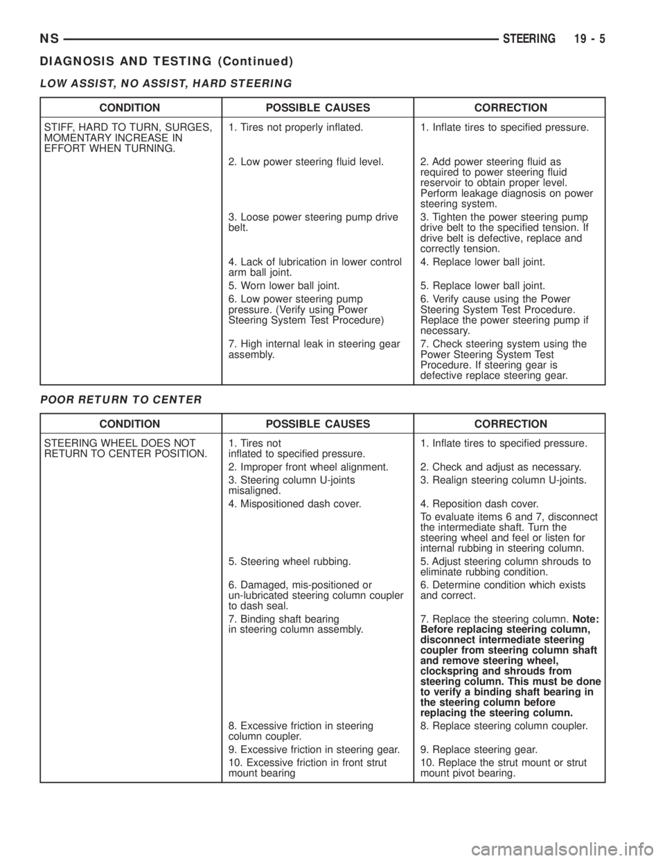
LOW ASSIST, NO ASSIST, HARD STEERING
POOR RETURN TO CENTER
CONDITION POSSIBLE CAUSES CORRECTION
STIFF, HARD TO TURN, SURGES,
MOMENTARY INCREASE IN
EFFORT WHEN TURNING.1. Tires not properly inflated. 1. Inflate tires to specified pressure.
2. Low power steering fluid level. 2. Add power steering fluid as
required to power steering fluid
reservoir to obtain proper level.
Perform leakage diagnosis on power
steering system.
3. Loose power steering pump drive
belt.3. Tighten the power steering pump
drive belt to the specified tension. If
drive belt is defective, replace and
correctly tension.
4. Lack of lubrication in lower control
arm ball joint.4. Replace lower ball joint.
5. Worn lower ball joint. 5. Replace lower ball joint.
6. Low power steering pump
pressure. (Verify using Power
Steering System Test Procedure)6. Verify cause using the Power
Steering System Test Procedure.
Replace the power steering pump if
necessary.
7. High internal leak in steering gear
assembly.7. Check steering system using the
Power Steering System Test
Procedure. If steering gear is
defective replace steering gear.
CONDITION POSSIBLE CAUSES CORRECTION
STEERING WHEEL DOES NOT
RETURN TO CENTER POSITION.1. Tires not
inflated to specified pressure.1. Inflate tires to specified pressure.
2. Improper front wheel alignment. 2. Check and adjust as necessary.
3. Steering column U-joints
misaligned.3. Realign steering column U-joints.
4. Mispositioned dash cover. 4. Reposition dash cover.
To evaluate items 6 and 7, disconnect
the intermediate shaft. Turn the
steering wheel and feel or listen for
internal rubbing in steering column.
5. Steering wheel rubbing. 5. Adjust steering column shrouds to
eliminate rubbing condition.
6. Damaged, mis-positioned or
un-lubricated steering column coupler
to dash seal.6. Determine condition which exists
and correct.
7. Binding shaft bearing
in steering column assembly.7. Replace the steering column.Note:
Before replacing steering column,
disconnect intermediate steering
coupler from steering column shaft
and remove steering wheel,
clockspring and shrouds from
steering column. This must be done
to verify a binding shaft bearing in
the steering column before
replacing the steering column.
8. Excessive friction in steering
column coupler.8. Replace steering column coupler.
9. Excessive friction in steering gear. 9. Replace steering gear.
10. Excessive friction in front strut
mount bearing10. Replace the strut mount or strut
mount pivot bearing.
NSSTEERING 19 - 5
DIAGNOSIS AND TESTING (Continued)
Page 1453 of 1938
The drive tangs on the pinion mate loosely with a
stub shaft to permit manual steering control to be
maintained if the drive belt on the power steering
pump should break. However, under these conditions,
steering effort will be increased.
DIAGNOSIS AND TESTING
POWER STEERING GEAR
The following procedure can be used to test the
operation of the power steering system on this vehi-
cle. This test will provide the flow rate for the power
steering system along with the maximum relief pres-
sure of the power steering pump. This test is to be
performed any time a power steering system problem
is present to determine if the power steering pump or
power steering gear is not functioning properly. The
following pressure and flow test is performed using
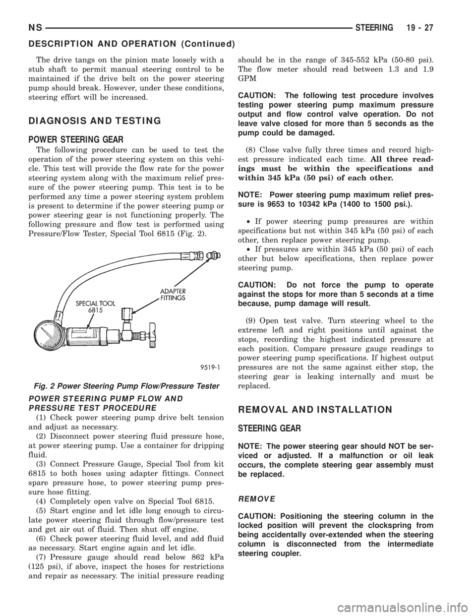
Pressure/Flow Tester, Special Tool 6815 (Fig. 2).
POWER STEERING PUMP FLOW AND
PRESSURE TEST PROCEDURE
(1) Check power steering pump drive belt tension
and adjust as necessary.
(2) Disconnect power steering fluid pressure hose,
at power steering pump. Use a container for dripping
fluid.
(3) Connect Pressure Gauge, Special Tool from kit
6815 to both hoses using adapter fittings. Connect
spare pressure hose, to power steering pump pres-
sure hose fitting.
(4) Completely open valve on Special Tool 6815.
(5) Start engine and let idle long enough to circu-
late power steering fluid through flow/pressure test
and get air out of fluid. Then shut off engine.
(6) Check power steering fluid level, and add fluid
as necessary. Start engine again and let idle.
(7) Pressure gauge should read below 862 kPa
(125 psi), if above, inspect the hoses for restrictions
and repair as necessary. The initial pressure readingshould be in the range of 345-552 kPa (50-80 psi).
The flow meter should read between 1.3 and 1.9
GPM
CAUTION: The following test procedure involves
testing power steering pump maximum pressure
output and flow control valve operation. Do not
leave valve closed for more than 5 seconds as the
pump could be damaged.
(8) Close valve fully three times and record high-
est pressure indicated each time.All three read-
ings must be within the specifications and
within 345 kPa (50 psi) of each other.
NOTE: Power steering pump maximum relief pres-
sure is 9653 to 10342 kPa (1400 to 1500 psi.).
²If power steering pump pressures are within
specifications but not within 345 kPa (50 psi) of each
other, then replace power steering pump.
²If pressures are within 345 kPa (50 psi) of each
other but below specifications, then replace power
steering pump.
CAUTION: Do not force the pump to operate
against the stops for more than 5 seconds at a time
because, pump damage will result.
(9) Open test valve. Turn steering wheel to the
extreme left and right positions until against the
stops, recording the highest indicated pressure at
each position. Compare pressure gauge readings to
power steering pump specifications. If highest output
pressures are not the same against either stop, the
steering gear is leaking internally and must be
replaced.REMOVAL AND INSTALLATION
STEERING GEAR
NOTE: The power steering gear should NOT be ser-
viced or adjusted. If a malfunction or oil leak
occurs, the complete steering gear assembly must
be replaced.
REMOVE
CAUTION: Positioning the steering column in the
locked position will prevent the clockspring from
being accidentally over-extended when the steering
column is disconnected from the intermediate
steering coupler.
Fig. 2 Power Steering Pump Flow/Pressure Tester
NSSTEERING 19 - 27
DESCRIPTION AND OPERATION (Continued)
Page 1462 of 1938
STEERING COLUMN
INDEX
page page
DESCRIPTION AND OPERATION
STEERING COLUMN DESCRIPTION......... 36
DIAGNOSIS AND TESTING
STEERING COLUMN..................... 38
SERVICE PROCEDURES
STEERING COLUMN SERVICE PROCEDURE
WARNINGS........................... 38REMOVAL AND INSTALLATION
STEERING COLUMN ASSEMBLY............ 38
SPECIFICATIONS
STEERING COLUMN FASTENER TORQUE
SPECIFICATIONS...................... 45
DESCRIPTION AND OPERATION
STEERING COLUMN DESCRIPTION
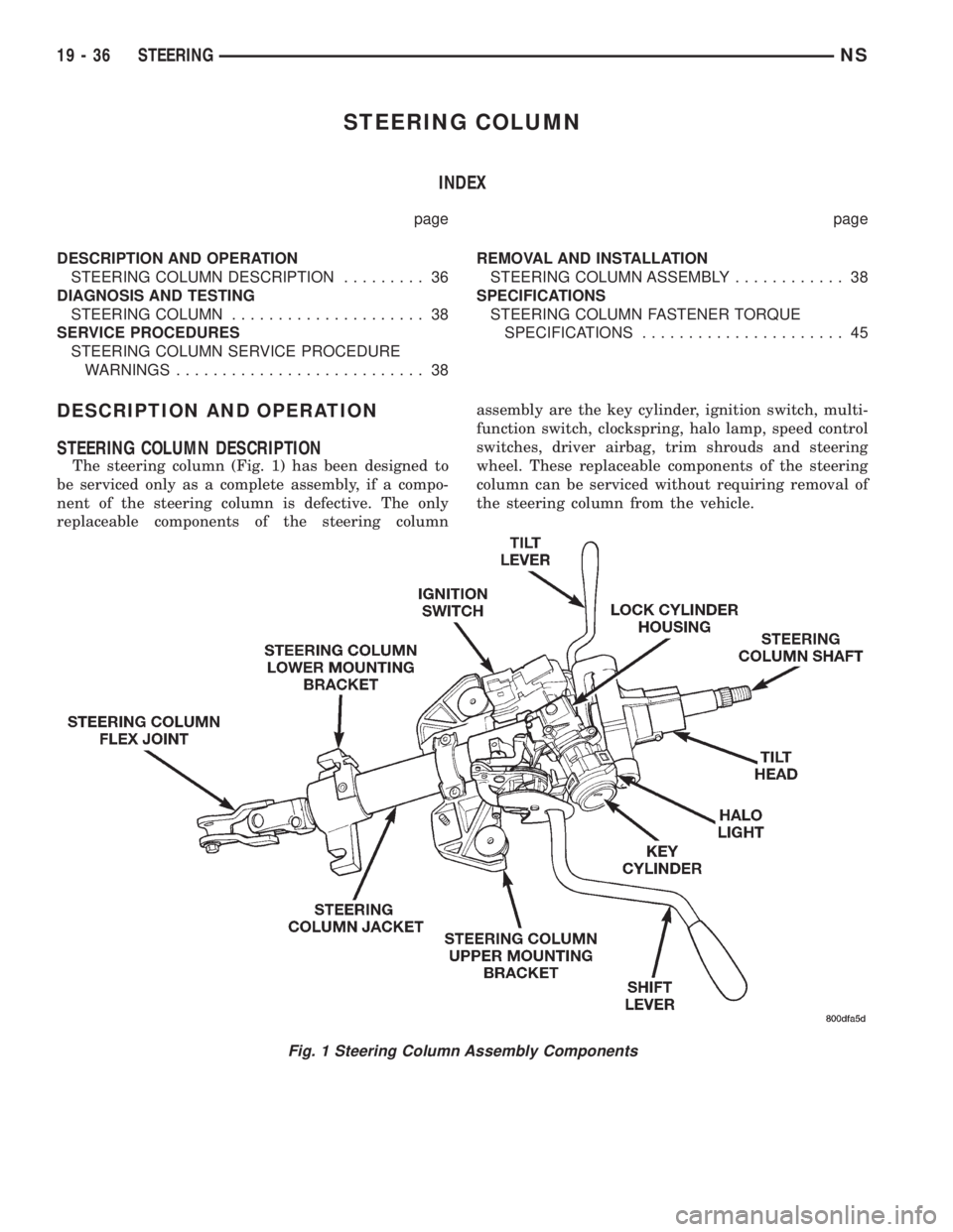
The steering column (Fig. 1) has been designed to
be serviced only as a complete assembly, if a compo-
nent of the steering column is defective. The only
replaceable components of the steering columnassembly are the key cylinder, ignition switch, multi-
function switch, clockspring, halo lamp, speed control
switches, driver airbag, trim shrouds and steering
wheel. These replaceable components of the steering
column can be serviced without requiring removal of
the steering column from the vehicle.
Fig. 1 Steering Column Assembly Components
19 - 36 STEERINGNS
Page 1466 of 1938
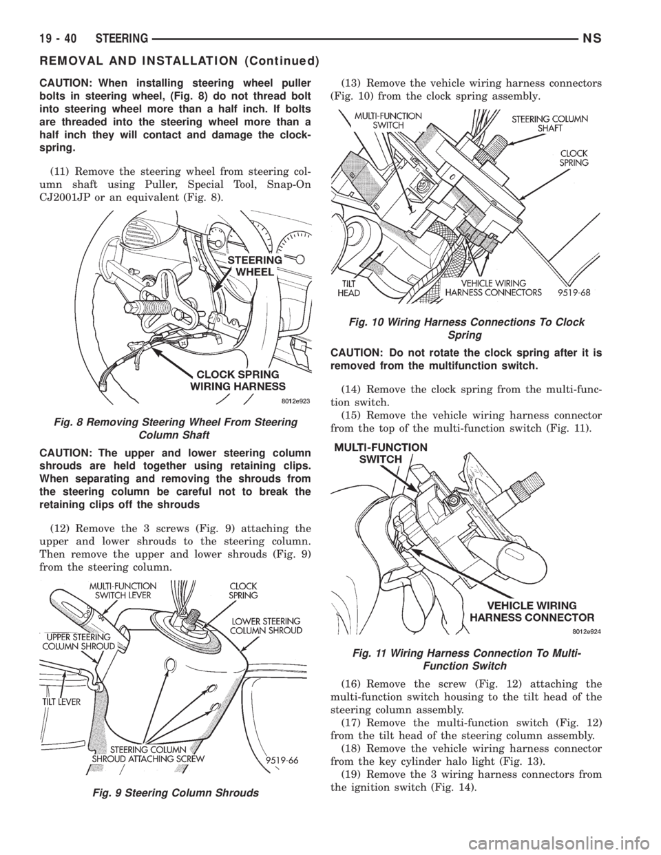
CAUTION: When installing steering wheel puller
bolts in steering wheel, (Fig. 8) do not thread bolt
into steering wheel more than a half inch. If bolts
are threaded into the steering wheel more than a
half inch they will contact and damage the clock-
spring.
(11) Remove the steering wheel from steering col-
umn shaft using Puller, Special Tool, Snap-On
CJ2001JP or an equivalent (Fig. 8).
CAUTION: The upper and lower steering column
shrouds are held together using retaining clips.
When separating and removing the shrouds from
the steering column be careful not to break the
retaining clips off the shrouds
(12) Remove the 3 screws (Fig. 9) attaching the
upper and lower shrouds to the steering column.
Then remove the upper and lower shrouds (Fig. 9)
from the steering column.(13) Remove the vehicle wiring harness connectors
(Fig. 10) from the clock spring assembly.
CAUTION: Do not rotate the clock spring after it is
removed from the multifunction switch.
(14) Remove the clock spring from the multi-func-
tion switch.
(15) Remove the vehicle wiring harness connector
from the top of the multi-function switch (Fig. 11).
(16) Remove the screw (Fig. 12) attaching the
multi-function switch housing to the tilt head of the
steering column assembly.
(17) Remove the multi-function switch (Fig. 12)
from the tilt head of the steering column assembly.
(18) Remove the vehicle wiring harness connector
from the key cylinder halo light (Fig. 13).
(19) Remove the 3 wiring harness connectors from
the ignition switch (Fig. 14).
Fig. 8 Removing Steering Wheel From Steering
Column Shaft
Fig. 9 Steering Column Shrouds
Fig. 10 Wiring Harness Connections To Clock
Spring
Fig. 11 Wiring Harness Connection To Multi-
Function Switch
19 - 40 STEERINGNS
REMOVAL AND INSTALLATION (Continued)
Page 1469 of 1938
(28) Remove steering column assembly from vehi-
cle. Use care to avoid damage to paint or interior
trim.
INSTALL
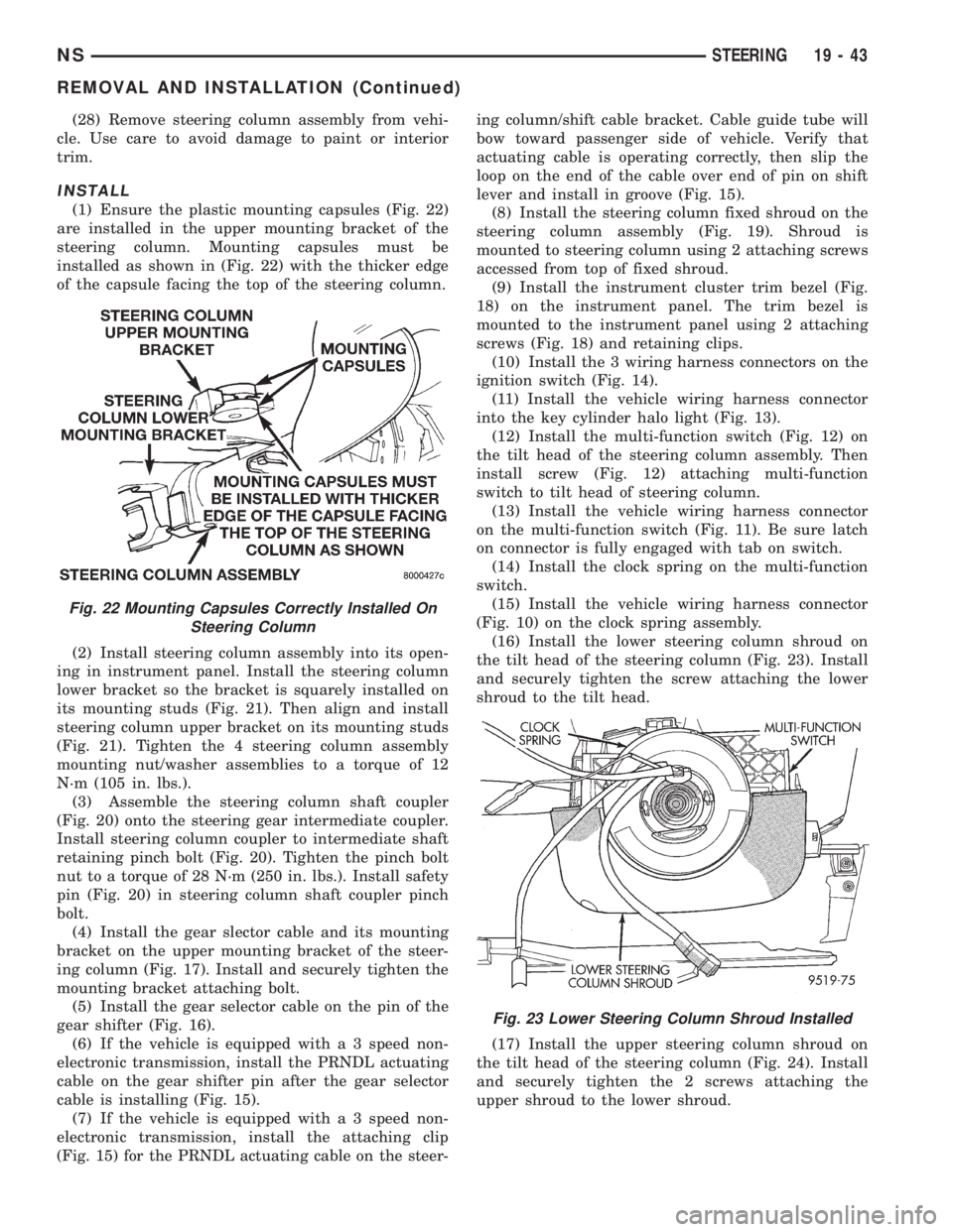
(1) Ensure the plastic mounting capsules (Fig. 22)
are installed in the upper mounting bracket of the
steering column. Mounting capsules must be
installed as shown in (Fig. 22) with the thicker edge
of the capsule facing the top of the steering column.
(2) Install steering column assembly into its open-
ing in instrument panel. Install the steering column
lower bracket so the bracket is squarely installed on
its mounting studs (Fig. 21). Then align and install
steering column upper bracket on its mounting studs
(Fig. 21). Tighten the 4 steering column assembly
mounting nut/washer assemblies to a torque of 12
N´m (105 in. lbs.).
(3) Assemble the steering column shaft coupler
(Fig. 20) onto the steering gear intermediate coupler.
Install steering column coupler to intermediate shaft
retaining pinch bolt (Fig. 20). Tighten the pinch bolt
nut to a torque of 28 N´m (250 in. lbs.). Install safety
pin (Fig. 20) in steering column shaft coupler pinch
bolt.
(4) Install the gear slector cable and its mounting
bracket on the upper mounting bracket of the steer-
ing column (Fig. 17). Install and securely tighten the
mounting bracket attaching bolt.
(5) Install the gear selector cable on the pin of the
gear shifter (Fig. 16).
(6) If the vehicle is equipped with a 3 speed non-
electronic transmission, install the PRNDL actuating
cable on the gear shifter pin after the gear selector
cable is installing (Fig. 15).
(7) If the vehicle is equipped with a 3 speed non-
electronic transmission, install the attaching clip
(Fig. 15) for the PRNDL actuating cable on the steer-ing column/shift cable bracket. Cable guide tube will
bow toward passenger side of vehicle. Verify that
actuating cable is operating correctly, then slip the
loop on the end of the cable over end of pin on shift
lever and install in groove (Fig. 15).
(8) Install the steering column fixed shroud on the
steering column assembly (Fig. 19). Shroud is
mounted to steering column using 2 attaching screws
accessed from top of fixed shroud.
(9) Install the instrument cluster trim bezel (Fig.
18) on the instrument panel. The trim bezel is
mounted to the instrument panel using 2 attaching
screws (Fig. 18) and retaining clips.
(10) Install the 3 wiring harness connectors on the
ignition switch (Fig. 14).
(11) Install the vehicle wiring harness connector
into the key cylinder halo light (Fig. 13).
(12) Install the multi-function switch (Fig. 12) on
the tilt head of the steering column assembly. Then
install screw (Fig. 12) attaching multi-function
switch to tilt head of steering column.
(13) Install the vehicle wiring harness connector
on the multi-function switch (Fig. 11). Be sure latch
on connector is fully engaged with tab on switch.
(14) Install the clock spring on the multi-function
switch.
(15) Install the vehicle wiring harness connector
(Fig. 10) on the clock spring assembly.
(16) Install the lower steering column shroud on
the tilt head of the steering column (Fig. 23). Install
and securely tighten the screw attaching the lower
shroud to the tilt head.
(17) Install the upper steering column shroud on
the tilt head of the steering column (Fig. 24). Install
and securely tighten the 2 screws attaching the
upper shroud to the lower shroud.
Fig. 22 Mounting Capsules Correctly Installed On
Steering Column
Fig. 23 Lower Steering Column Shroud Installed
NSSTEERING 19 - 43
REMOVAL AND INSTALLATION (Continued)
Page 1470 of 1938
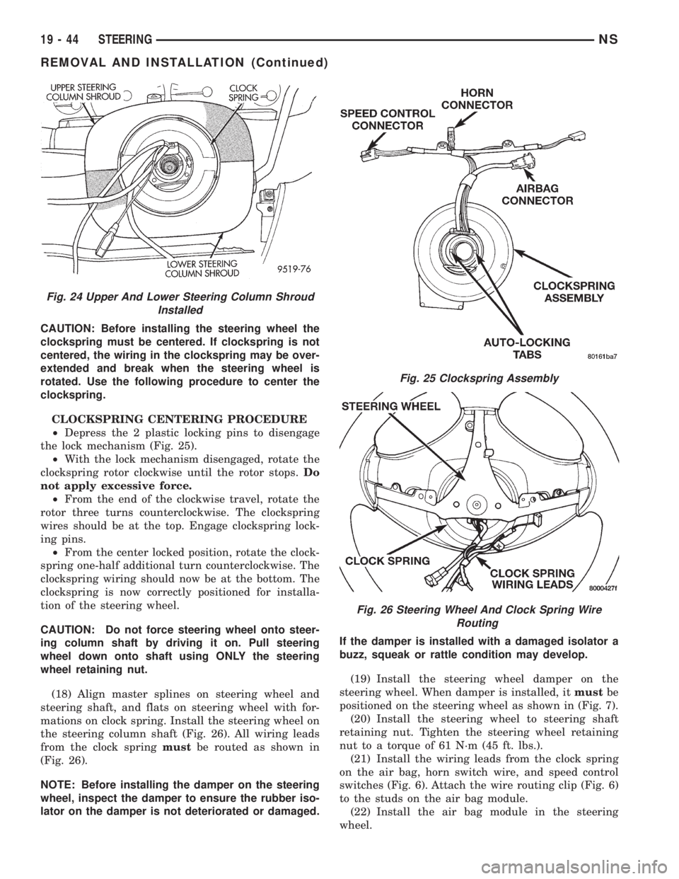
CAUTION: Before installing the steering wheel the
clockspring must be centered. If clockspring is not
centered, the wiring in the clockspring may be over-
extended and break when the steering wheel is
rotated. Use the following procedure to center the
clockspring.
CLOCKSPRING CENTERING PROCEDURE
²Depress the 2 plastic locking pins to disengage
the lock mechanism (Fig. 25).
²With the lock mechanism disengaged, rotate the
clockspring rotor clockwise until the rotor stops.Do
not apply excessive force.
²From the end of the clockwise travel, rotate the
rotor three turns counterclockwise. The clockspring
wires should be at the top. Engage clockspring lock-
ing pins.
²From the center locked position, rotate the clock-
spring one-half additional turn counterclockwise. The
clockspring wiring should now be at the bottom. The
clockspring is now correctly positioned for installa-
tion of the steering wheel.
CAUTION: Do not force steering wheel onto steer-
ing column shaft by driving it on. Pull steering
wheel down onto shaft using ONLY the steering
wheel retaining nut.
(18) Align master splines on steering wheel and
steering shaft, and flats on steering wheel with for-
mations on clock spring. Install the steering wheel on
the steering column shaft (Fig. 26). All wiring leads
from the clock springmustbe routed as shown in
(Fig. 26).
NOTE: Before installing the damper on the steering
wheel, inspect the damper to ensure the rubber iso-
lator on the damper is not deteriorated or damaged.If the damper is installed with a damaged isolator a
buzz, squeak or rattle condition may develop.
(19) Install the steering wheel damper on the
steering wheel. When damper is installed, itmustbe
positioned on the steering wheel as shown in (Fig. 7).
(20) Install the steering wheel to steering shaft
retaining nut. Tighten the steering wheel retaining
nut to a torque of 61 N´m (45 ft. lbs.).
(21) Install the wiring leads from the clock spring
on the air bag, horn switch wire, and speed control
switches (Fig. 6). Attach the wire routing clip (Fig. 6)
to the studs on the air bag module.
(22) Install the air bag module in the steering
wheel.
Fig. 24 Upper And Lower Steering Column Shroud
Installed
Fig. 25 Clockspring Assembly
Fig. 26 Steering Wheel And Clock Spring Wire
Routing
19 - 44 STEERINGNS
REMOVAL AND INSTALLATION (Continued)