clock CHRYSLER VOYAGER 1996 Service Manual
[x] Cancel search | Manufacturer: CHRYSLER, Model Year: 1996, Model line: VOYAGER, Model: CHRYSLER VOYAGER 1996Pages: 1938, PDF Size: 55.84 MB
Page 1487 of 1938
may not be detected. Practically any condition can be
caused by leaking hydraulic circuits or sticking
valves.
Therefore, unless the condition is obvious, the tran-
saxle should never be disassembled until hydraulic
pressure tests have been performed.
HYDRAULIC PRESSURE TESTS
Pressure testing is a very important step in the
diagnostic procedure. These tests usually reveal the
cause of most transaxle problems.
Before performing pressure tests, be certain that
fluid level and condition, and control cable adjust-
ments have been checked and approved. Fluid must
be at operating temperature (150 to 200 degrees F.).
Install an engine tachometer, raise vehicle on hoist
which allows front wheels to turn, and position
tachometer so it can be read.
Disconnect throttle cable and shift cable from tran-
saxle levers so they can be controlled from outside
the vehicle.
Attach 150 psi gauges to ports required for test
being conducted. A 300 psi gauge (C-3293) is required
for reverse pressure test at rear servo.
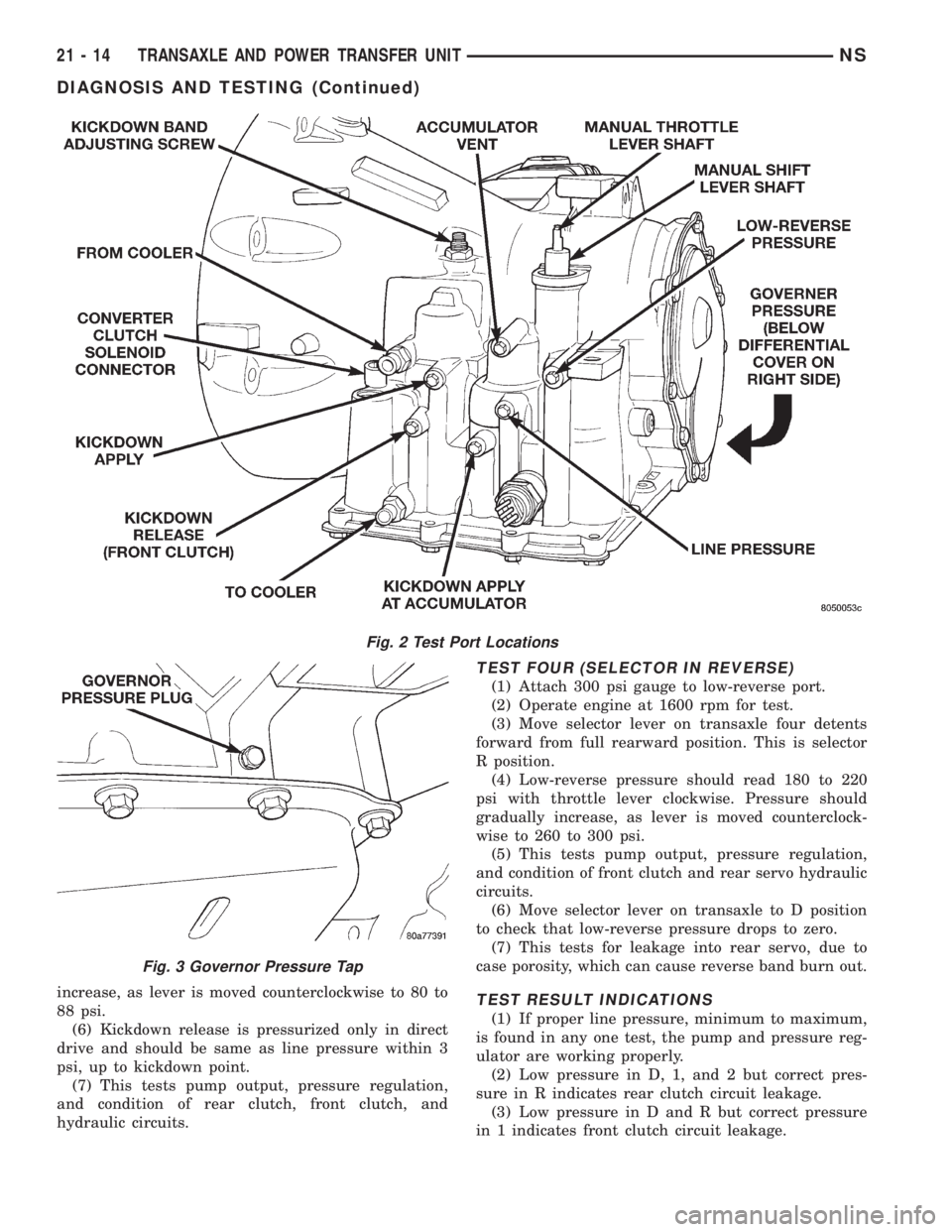
Test port locations are shown in (Fig. 2) .
TEST ONE (SELECTOR IN 1)
(1) Attach gauges to line and low-reverse ports.
(2) Operate engine at 1000 rpm for test.
(3) Move selector lever on transaxle all the way
rearward (1 position).
(4) Read pressures on both gauges as throttle lever
on transaxle is moved from full clockwise position to
full counterclockwise position.
(5) Line pressure should read 52 to 58 psi with
throttle lever clockwise. Pressure should gradually
increase, as lever is moved counterclockwise, to 80 to
88 psi.(6) Low-reverse pressure should read the same as
line pressure within 3 psi.
(7) This tests pump output, pressure regulation,
and condition of rear clutch and rear servo hydraulic
circuits.
TEST TWO (SELECTOR IN 2)
(1) Attach one gauge to line pressure port and tee
another gauge into lower cooler line fitting. This will
allow lubrication pressure readings to be taken..
(2) Operate engine at 1000 rpm for test.
(3) Move selector lever on transaxle one detent for-
ward from full rearward position. This is selector 2
position.
(4) Read pressures on both gauges as throttle lever
on transaxle is moved from full clockwise position to
full counterclockwise position.
(5) Line pressure should read 52 to 58 psi with
throttle lever clockwise. Pressure should gradually
increase, as lever is moved counterclockwise, to 80 to
88 psi.
(6) Lubrication pressure should be 10 to 25 psi
with lever clockwise and 10 to 35 psi with lever full
counterclockwise.
(7) This tests pump output, pressure regulation,
and condition of rear clutch and lubrication hydraulic
circuits.
TEST THREE (SELECTOR IN D)
(1) Attach gauges to line and kickdown release
ports.
(2) Operate engine at 1600 rpm for test.
(3) Move selector lever on transaxle two detents
forward from full rearward position. This is selector
D position.
(4) Read pressures on both gauges as throttle lever
on transaxle is moved from full clockwise position to
full counterclockwise position.
(5) Line pressure should read 52 to 58 psi with
throttle lever clockwise. Pressure should gradually
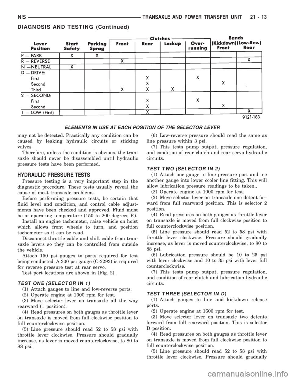
ELEMENTS IN USE AT EACH POSITION OF THE SELECTOR LEVER
NSTRANSAXLE AND POWER TRANSFER UNIT 21 - 13
DIAGNOSIS AND TESTING (Continued)
Page 1488 of 1938
increase, as lever is moved counterclockwise to 80 to
88 psi.
(6) Kickdown release is pressurized only in direct
drive and should be same as line pressure within 3
psi, up to kickdown point.
(7) This tests pump output, pressure regulation,
and condition of rear clutch, front clutch, and
hydraulic circuits.
TEST FOUR (SELECTOR IN REVERSE)
(1) Attach 300 psi gauge to low-reverse port.
(2) Operate engine at 1600 rpm for test.
(3) Move selector lever on transaxle four detents
forward from full rearward position. This is selector
R position.
(4) Low-reverse pressure should read 180 to 220
psi with throttle lever clockwise. Pressure should
gradually increase, as lever is moved counterclock-
wise to 260 to 300 psi.
(5) This tests pump output, pressure regulation,
and condition of front clutch and rear servo hydraulic
circuits.
(6) Move selector lever on transaxle to D position
to check that low-reverse pressure drops to zero.
(7) This tests for leakage into rear servo, due to
case porosity, which can cause reverse band burn out.
TEST RESULT INDICATIONS
(1) If proper line pressure, minimum to maximum,
is found in any one test, the pump and pressure reg-
ulator are working properly.
(2) Low pressure in D, 1, and 2 but correct pres-
sure in R indicates rear clutch circuit leakage.
(3) Low pressure in D and R but correct pressure
in 1 indicates front clutch circuit leakage.
Fig. 2 Test Port Locations
Fig. 3 Governor Pressure Tap
21 - 14 TRANSAXLE AND POWER TRANSFER UNITNS
DIAGNOSIS AND TESTING (Continued)
Page 1494 of 1938
(5) Continuity should exist only with transaxle in
Reverse position.
(6) No continuity should exist from either pin to
the case.
TRANSAXLE AND TORQUE CONVERTER REMOVAL
NOTE: Transaxle removal does NOT require engine
removal.
The transaxle and torque converter must be
removed as an assembly; otherwise, the torque con-
verter drive plate, pump bushing, or oil seal may be
damaged. The drive plate will not support a load;
therefore, none of the weight of the transaxle should
be allowed to rest on the plate during removal.
REMOVAL
(1) Disconnect negative battery cable.
(2) Remove air cleaner and hoses.
(3) Disconnect throttle linkage and shift linkage
from transaxle.
(4) Unplug torque converter clutch connector,
located near the dipstick. Unplug the gear position
switch.
(5) Remove transaxle dipstick tube.
(6) Remove the transaxle cooler lines and plug.
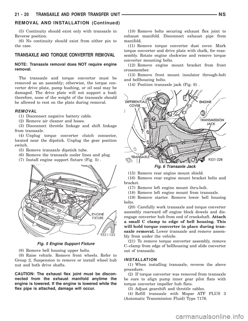
(7) Install engine support fixture (Fig. 5) .
(8) Remove bell housing upper bolts.
(9) Raise vehicle. Remove front wheels. Refer to
Group 2, Suspension to remove or install wheel hub
nut and both drive shafts.
CAUTION: The exhaust flex joint must be discon-
nected from the exhaust manifold anytime the
engine is lowered. If the engine is lowered while the
flex pipe is attached, damage will occur.(10) Remove bolts securing exhaust flex joint to
exhaust manifold. Disconnect exhaust pipe from
manifold.
(11) Remove torque converter dust cover. Mark
torque converter and drive plate with chalk, for reas-
sembly. Rotate engine clockwise and remove torque
converter mounting bolts.
(12) Remove engine mount bracket from front
crossmember.
(13) Remove front mount insulator through-bolt
and bellhousing bolts.
(14) Position transaxle jack (Fig. 6) .
(15) Remove rear engine mount shield.
(16) Remove rear engine mount bracket bolts and
bracket.
(17) Remove left engine mount thru-bolt.
(18) Remove left engine mount from transaxle.
(19) Remove starter. Remove lower bell housing
bolts.
(20) Carefully work transaxle and torque converter
assembly rearward off engine block dowels and dis-
engage converter hub from end of crankshaft.Attach
a small C clamp to edge of bell housing. This
will hold torque converter in place during tran-
saxle removal.Lower transaxle and remove assem-
bly from under the vehicle.
(21) To remove torque converter assembly, remove
C±clamp from edge of bellhousing and slide converter
out of transaxle.
INSTALLATION
(1) When installing transaxle, reverse the above
procedure.
(2) If torque converter was removed from transaxle
be sure to align pump inner gear pilot flats with
torque converter impeller hub flats.
(3) Adjust gearshift and throttle cables.
(4) Refill transaxle with Mopar ATF PLUS 3
(Automatic Transmission Fluid) Type 7176.
Fig. 5 Engine Support Fixture
Fig. 6 Transaxle Jack
21 - 20 TRANSAXLE AND POWER TRANSFER UNITNS
REMOVAL AND INSTALLATION (Continued)
Page 1526 of 1938

(3) Back off adjusting screw the number of turns
listed in Specifications. Hold adjusting screw in this
position and tighten locknut to 47 N´m (35ft. lbs.)
LOW/REVERSE BAND (REAR)
To adjust low-reverse band, proceed as follows:
(1) Loosen and back off locknut approximately 5
turns.
(2) Using an inch-pound torque wrench, tighten
adjusting screw to 5 N´m (41 in. lbs.) true torque.
(3) Back off adjusting screw the number of turns
listed under Specifications. This chart is located at
the rear of this section.
(4) Tighten locknut to 14 N´m (10 ft. lbs.).
HYDRAULIC CONTROL PRESSURE ADJUSTMENTS
LINE PRESSURE
An incorrect throttle pressure setting will cause
incorrect line pressure readings even though line
pressure adjustment is correct. Always inspect and
correct throttle pressure adjustment before adjusting
the line pressure.
The approximate adjustment for line pressure is
1-5/16 inches, measured from valve body to inner
edge of adjusting nut. However, due to manufactur-
ing tolerances, the adjustment can be varied to
obtain specified line pressure.
The adjusting screw may be turned with an Allen
wrench. One complete turn of adjusting screw
changes closed throttle line pressure approximately
1-2/3 psi. Turning adjusting screw counterclockwise
increases pressure, and clockwise decreases pressure.
THROTTLE PRESSURE
Throttle pressures cannot be tested accurately;
therefore, the adjustment should be measured if a
malfunction is evident.
(1) Insert gauge pin of Tool C-3763 between the
throttle lever cam and kickdown valve.
(2) By pushing in on tool, compress kickdown
valve against its spring so throttle valve is com-
pletely bottomed inside the valve body.
(3) While compressing spring, turn throttle lever
stop screw with adapter C-4553. Turn until head of
screw touches throttle lever tang, with throttle lever
cam touching tool and throttle valve bottomed. Be
sure adjustment is made with spring fully com-
pressed and valve bottomed in the valve body.
BEARING ADJUSTMENT PROCEDURES
(1) Take extreme care when removing and install-
ing bearing cups and cones.Use only an arbor
press for installation, as a hammer may not
properly align the bearing cup or cone.Burrs or
nicks on the bearing seat will give a false end play
reading, while gauging for proper shims. Improperlyseated bearing cup and cones are subject to low-mile-
age failure.
(2) Bearing cups and cones should be replaced if
they show signs of pitting or heat distress.
(3) If distress is seen on either the cup or bearing
rollers, both cup and cone must be replaced.
NOTE: Bearing end play and drag torque specifica-
tions must be maintained to avoid premature bear-
ing failures.
(4) Used (original) bearing may lose up to 50 per-
cent of the original drag torque after break-in.
NOTE: All bearing adjustments must be made with
no other component interference or gear inter-
mesh, except the transfer gear bearing.
(5) Refer to the conversion chart in specifications
to convert inches to millimeter measurements. Refer
to bearing shim chart for proper shim thicknesses.
OUTPUT SHAFT BEARING
(1) With output shaft gear removed, install a 13.65
mm (.537 inch) and a 1.34 mm (.053 inch) gauging
shims on the planetary rear annulus gear hub using
grease to hold the shims in place. The 13.65 mm
shim has a larger inside diameter and must be
installed over the output shaft first. The 1.34 mm
shim pilots on the output shaft.
(2) Install output shaft gear and bearing assembly,
torque to 271 N´m (200 ft. lbs.).
(3) To measure bearing end play:
(4) Attach Tool L-4432 to the output shaft gear.
(5) Mount a steel ball with grease into the end of
the output shaft.
(6) Push and pull the gear while rotating back and
forth to insure seating of the bearing rollers.
(7) Using a dial indicator, mounted to the tran-
saxle case, measure output shaft end play.
(8) Once bearing end play has been determined,
refer to the output shaft bearing shim chart.
(9) The 12.65 mm (.498 inch), 13.15 mm (.518
inch) or 13.65 mm (.537 inch) shims are always
installed first.These shims have lubrication slots
which are necessary for proper bearing lubrica-
tion.
(10) Shims thinner than 12.65 mm listed in the
chart are common to both the transfer shaft and out-
put shaft bearings.
(11) Use Tool L-4434 to remove the retaining nut
and washer. To remove the output shaft gear use Tool
L-4407.
(12) Remove the two gauging shims and install the
proper shim combination, making sure to install the
12.65, 13.15, or 13.65 mm shim first. Use grease to
21 - 52 TRANSAXLE AND POWER TRANSFER UNITNS
ADJUSTMENTS (Continued)
Page 1562 of 1938
VALVE BODY
REMOVAL
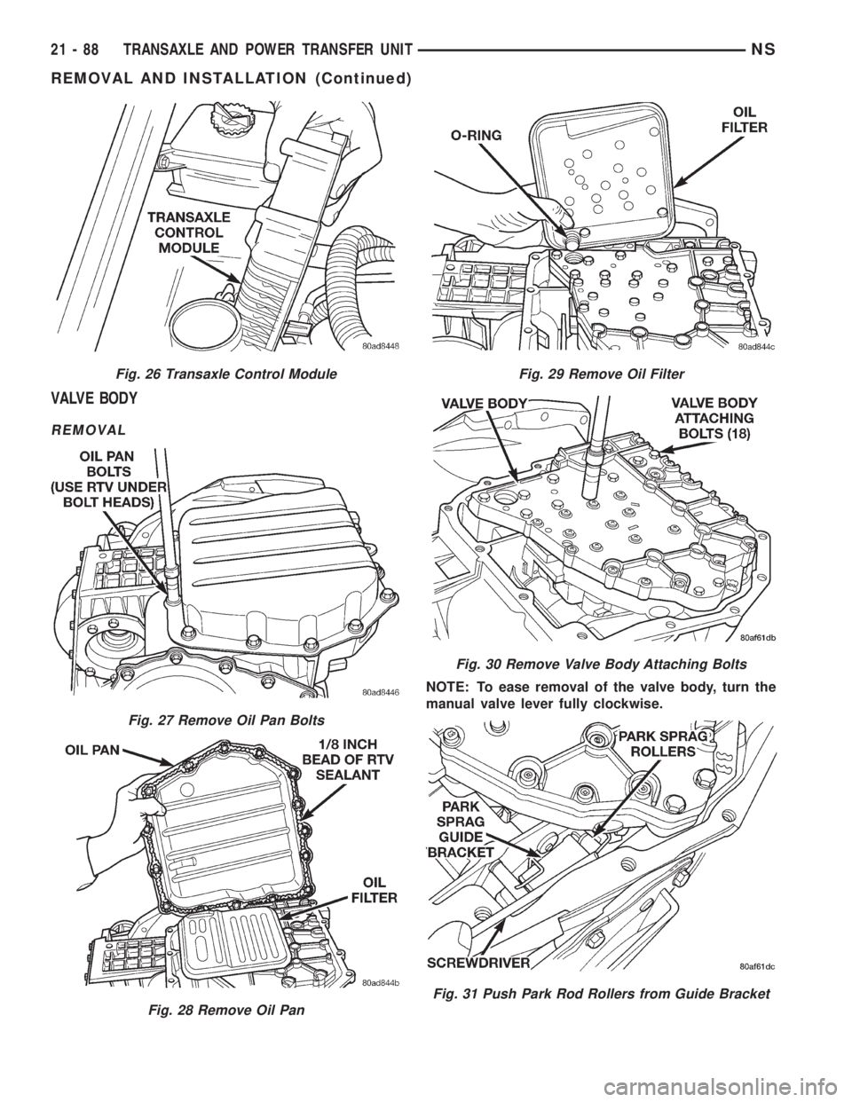
NOTE: To ease removal of the valve body, turn the
manual valve lever fully clockwise.
Fig. 26 Transaxle Control Module
Fig. 27 Remove Oil Pan Bolts
Fig. 28 Remove Oil Pan
Fig. 29 Remove Oil Filter
Fig. 30 Remove Valve Body Attaching Bolts
Fig. 31 Push Park Rod Rollers from Guide Bracket
21 - 88 TRANSAXLE AND POWER TRANSFER UNITNS
REMOVAL AND INSTALLATION (Continued)
Page 1563 of 1938
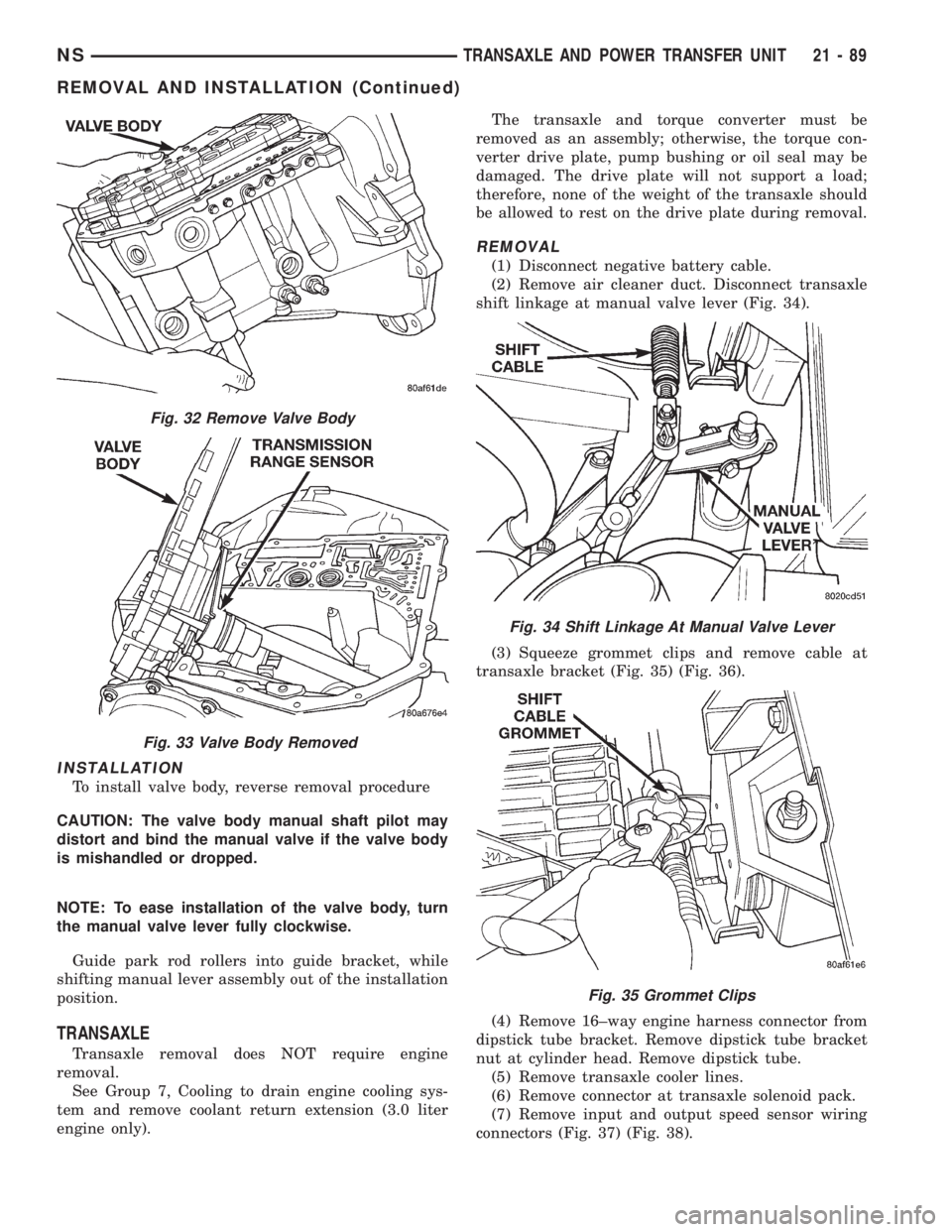
INSTALLATION
To install valve body, reverse removal procedure
CAUTION: The valve body manual shaft pilot may
distort and bind the manual valve if the valve body
is mishandled or dropped.
NOTE: To ease installation of the valve body, turn
the manual valve lever fully clockwise.
Guide park rod rollers into guide bracket, while
shifting manual lever assembly out of the installation
position.
TRANSAXLE
Transaxle removal does NOT require engine
removal.
See Group 7, Cooling to drain engine cooling sys-
tem and remove coolant return extension (3.0 liter
engine only).The transaxle and torque converter must be
removed as an assembly; otherwise, the torque con-
verter drive plate, pump bushing or oil seal may be
damaged. The drive plate will not support a load;
therefore, none of the weight of the transaxle should
be allowed to rest on the drive plate during removal.
REMOVAL
(1) Disconnect negative battery cable.
(2) Remove air cleaner duct. Disconnect transaxle
shift linkage at manual valve lever (Fig. 34).
(3) Squeeze grommet clips and remove cable at
transaxle bracket (Fig. 35) (Fig. 36).
(4) Remove 16±way engine harness connector from
dipstick tube bracket. Remove dipstick tube bracket
nut at cylinder head. Remove dipstick tube.
(5) Remove transaxle cooler lines.
(6) Remove connector at transaxle solenoid pack.
(7) Remove input and output speed sensor wiring
connectors (Fig. 37) (Fig. 38).
Fig. 32 Remove Valve Body
Fig. 33 Valve Body Removed
Fig. 34 Shift Linkage At Manual Valve Lever
Fig. 35 Grommet Clips
NSTRANSAXLE AND POWER TRANSFER UNIT 21 - 89
REMOVAL AND INSTALLATION (Continued)
Page 1565 of 1938
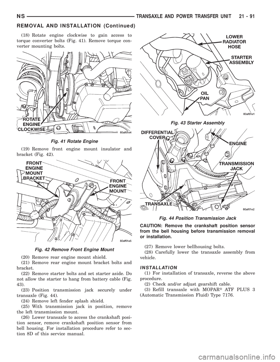
(18) Rotate engine clockwise to gain access to
torque converter bolts (Fig. 41). Remove torque con-
verter mounting bolts.
(19) Remove front engine mount insulator and
bracket (Fig. 42).
(20) Remove rear engine mount shield.
(21) Remove rear engine mount bracket bolts and
bracket.
(22) Remove starter bolts and set starter aside. Do
not allow the starter to hang from battery cable (Fig.
43).
(23) Position transmission jack securely under
transaxle (Fig. 44).
(24) Remove left fender splash shield.
(25) With transmission jack in position, remove
the left transmission mount.
(26) Lower transaxle to access the crankshaft posi-
tion sensor, remove crankshaft position sensor from
bell housing. For installation procedure refer to sec-
tion 8D of this service manual.CAUTION: Remove the crankshaft position sensor
from the bell housing before transmission removal
or installation.
(27) Remove lower bellhousing bolts.
(28) Carefully lower the transaxle assembly from
vehicle.
INSTALLATION
(1) For installation of transaxle, reverse the above
procedure.
(2) Check and/or adjust gearshift cable.
(3) Refill transaxle with MOPARtATF PLUS 3
(Automatic Transmission Fluid) Type 7176.
Fig. 41 Rotate Engine
Fig. 42 Remove Front Engine Mount
Fig. 43 Starter Assembly
Fig. 44 Position Transmission Jack
NSTRANSAXLE AND POWER TRANSFER UNIT 21 - 91
REMOVAL AND INSTALLATION (Continued)
Page 1570 of 1938
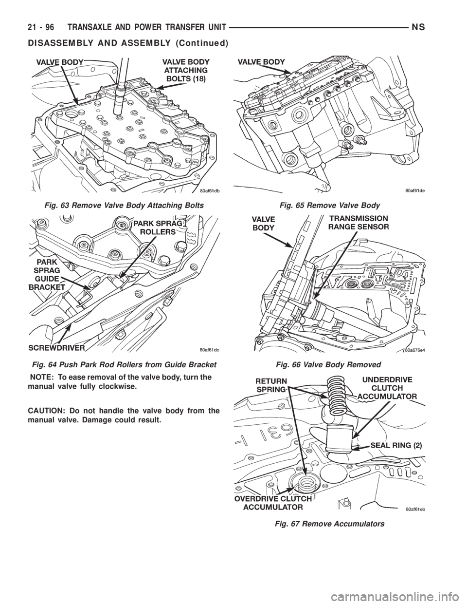
NOTE: To ease removal of the valve body, turn the
manual valve fully clockwise.
CAUTION: Do not handle the valve body from the
manual valve. Damage could result.
Fig. 63 Remove Valve Body Attaching Bolts
Fig. 64 Push Park Rod Rollers from Guide Bracket
Fig. 65 Remove Valve Body
Fig. 66 Valve Body Removed
Fig. 67 Remove Accumulators
21 - 96 TRANSAXLE AND POWER TRANSFER UNITNS
DISASSEMBLY AND ASSEMBLY (Continued)
Page 1602 of 1938

Fig. 231 Install Strap Bolts
Fig. 232 Turn Stirrup Clockwise Against Flats Of
Output Gear Retaining Bolt
Fig. 233 Tighten Stirrup Strap Bolts To 23 N´m
(200 in. lbs.)
Fig. 234 Bend Tabs On Strap Up Against Flats Of
Bolts
Fig. 235 Install Transfer Shaft Bearing Cone
Fig. 236 Install Bearing Cup To Shaft
21 - 128 TRANSAXLE AND POWER TRANSFER UNITNS
DISASSEMBLY AND ASSEMBLY (Continued)
Page 1611 of 1938
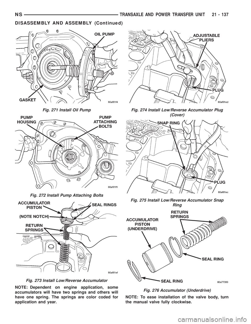
NOTE: Dependent on engine application, some
accumulators will have two springs and others will
have one spring. The springs are color coded for
application and year.NOTE: To ease installation of the valve body, turn
the manual valve fully clockwise.
Fig. 271 Install Oil Pump
Fig. 272 Install Pump Attaching Bolts
Fig. 273 Install Low/Reverse Accumulator
Fig. 274 Install Low/Reverse Accumulator Plug
(Cover)
Fig. 275 Install Low/Reverse Accumulator Snap
Ring
Fig. 276 Accumulator (Underdrive)
NSTRANSAXLE AND POWER TRANSFER UNIT 21 - 137
DISASSEMBLY AND ASSEMBLY (Continued)