clock CHRYSLER VOYAGER 1996 Manual Online
[x] Cancel search | Manufacturer: CHRYSLER, Model Year: 1996, Model line: VOYAGER, Model: CHRYSLER VOYAGER 1996Pages: 1938, PDF Size: 55.84 MB
Page 1163 of 1938
with the dot on the sprocket and install camshaft
sprocket into position.
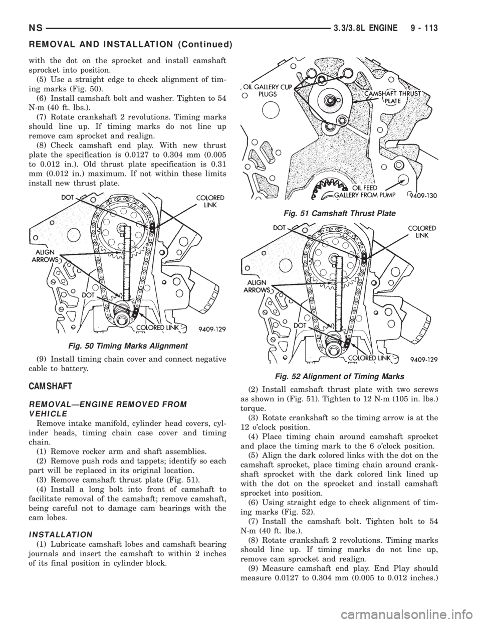
(5) Use a straight edge to check alignment of tim-
ing marks (Fig. 50).
(6) Install camshaft bolt and washer. Tighten to 54
N┬┤m (40 ft. lbs.).
(7) Rotate crankshaft 2 revolutions. Timing marks
should line up. If timing marks do not line up
remove cam sprocket and realign.
(8) Check camshaft end play. With new thrust
plate the specification is 0.0127 to 0.304 mm (0.005
to 0.012 in.). Old thrust plate specification is 0.31
mm (0.012 in.) maximum. If not within these limits
install new thrust plate.
(9) Install timing chain cover and connect negative
cable to battery.
CAMSHAFT
REMOVALÐENGINE REMOVED FROM
VEHICLE
Remove intake manifold, cylinder head covers, cyl-
inder heads, timing chain case cover and timing
chain.
(1) Remove rocker arm and shaft assemblies.
(2) Remove push rods and tappets; identify so each
part will be replaced in its original location.
(3) Remove camshaft thrust plate (Fig. 51).
(4) Install a long bolt into front of camshaft to
facilitate removal of the camshaft; remove camshaft,
being careful not to damage cam bearings with the
cam lobes.
INSTALLATION
(1) Lubricate camshaft lobes and camshaft bearing
journals and insert the camshaft to within 2 inches
of its final position in cylinder block.(2) Install camshaft thrust plate with two screws
as shown in (Fig. 51). Tighten to 12 N┬┤m (105 in. lbs.)
torque.
(3) Rotate crankshaft so the timing arrow is at the
12 o'clock position.
(4) Place timing chain around camshaft sprocket
and place the timing mark to the 6 o'clock position.
(5) Align the dark colored links with the dot on the
camshaft sprocket, place timing chain around crank-
shaft sprocket with the dark colored link lined up
with the dot on the sprocket and install camshaft
sprocket into position.
(6) Using straight edge to check alignment of tim-
ing marks (Fig. 52).
(7) Install the camshaft bolt. Tighten bolt to 54
N┬┤m (40 ft. lbs.).
(8) Rotate crankshaft 2 revolutions. Timing marks
should line up. If timing marks do not line up,
remove cam sprocket and realign.
(9) Measure camshaft end play. End Play should
measure 0.0127 to 0.304 mm (0.005 to 0.012 inches.)
Fig. 50 Timing Marks Alignment
Fig. 51 Camshaft Thrust Plate
Fig. 52 Alignment of Timing Marks
NS3.3/3.8L ENGINE 9 - 113
REMOVAL AND INSTALLATION (Continued)
Page 1167 of 1938
(3) Slowly rotate crankshaft clockwise, forcing out
upper half of bearing shell.
INSTALLATION
NOTE: Only one main bearing should be selec-
tively fitted while all other main bearing caps are
properly tightened.
When installing a new upper bearing shell, slightly
chamfer the sharp edges from the plain side.
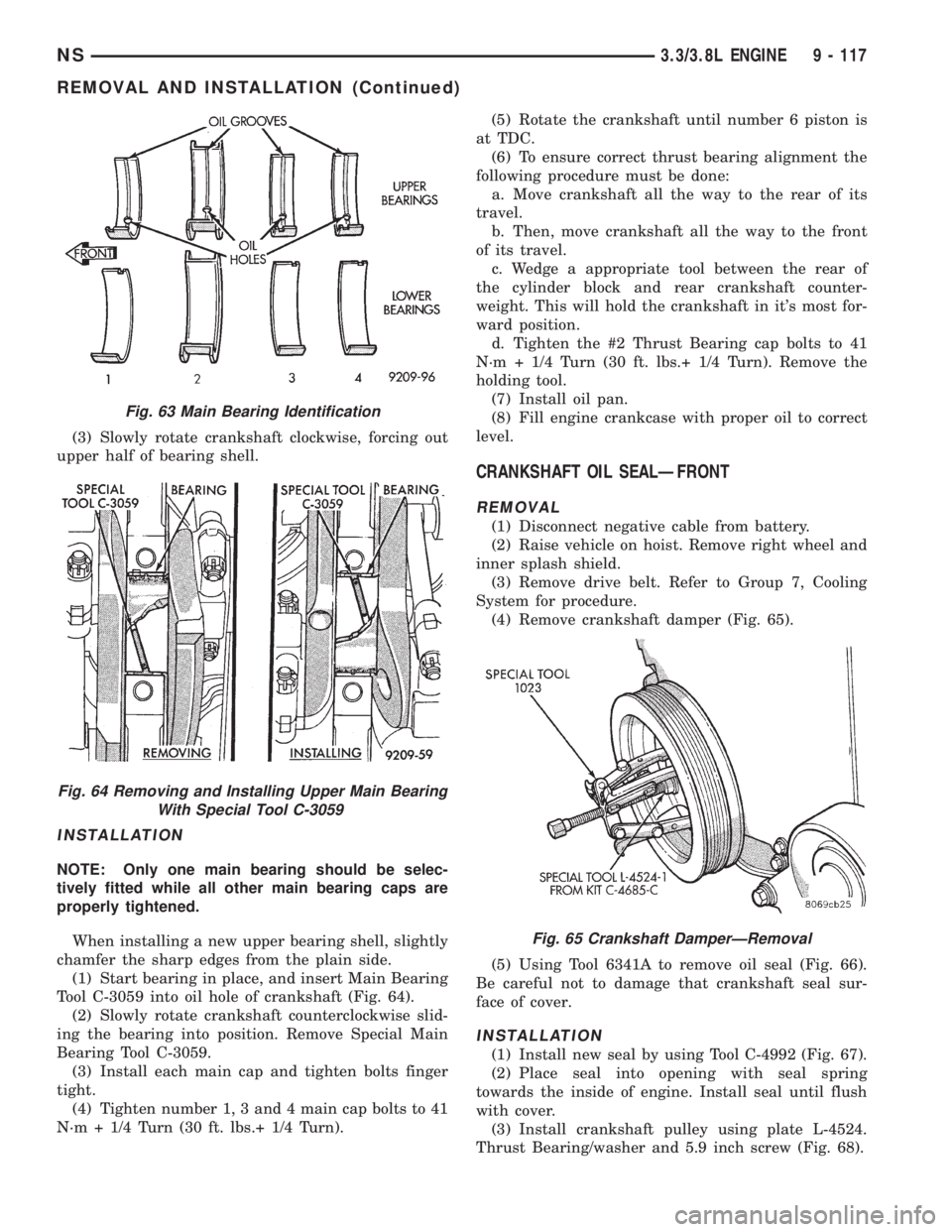
(1) Start bearing in place, and insert Main Bearing
Tool C-3059 into oil hole of crankshaft (Fig. 64).
(2) Slowly rotate crankshaft counterclockwise slid-
ing the bearing into position. Remove Special Main
Bearing Tool C-3059.
(3) Install each main cap and tighten bolts finger
tight.
(4) Tighten number 1, 3 and 4 main cap bolts to 41
N┬┤m + 1/4 Turn (30 ft. lbs.+ 1/4 Turn).(5) Rotate the crankshaft until number 6 piston is
at TDC.
(6) To ensure correct thrust bearing alignment the
following procedure must be done:
a. Move crankshaft all the way to the rear of its
travel.
b. Then, move crankshaft all the way to the front
of its travel.
c. Wedge a appropriate tool between the rear of
the cylinder block and rear crankshaft counter-
weight. This will hold the crankshaft in it's most for-
ward position.
d. Tighten the #2 Thrust Bearing cap bolts to 41
N┬┤m + 1/4 Turn (30 ft. lbs.+ 1/4 Turn). Remove the
holding tool.
(7) Install oil pan.
(8) Fill engine crankcase with proper oil to correct
level.
CRANKSHAFT OIL SEALÐFRONT
REMOVAL
(1) Disconnect negative cable from battery.
(2) Raise vehicle on hoist. Remove right wheel and
inner splash shield.
(3) Remove drive belt. Refer to Group 7, Cooling
System for procedure.
(4) Remove crankshaft damper (Fig. 65).
(5) Using Tool 6341A to remove oil seal (Fig. 66).
Be careful not to damage that crankshaft seal sur-
face of cover.
INSTALLATION
(1) Install new seal by using Tool C-4992 (Fig. 67).
(2) Place seal into opening with seal spring
towards the inside of engine. Install seal until flush
with cover.
(3) Install crankshaft pulley using plate L-4524.
Thrust Bearing/washer and 5.9 inch screw (Fig. 68).
Fig. 63 Main Bearing Identification
Fig. 64 Removing and Installing Upper Main Bearing
With Special Tool C-3059
Fig. 65 Crankshaft DamperÐRemoval
NS3.3/3.8L ENGINE 9 - 117
REMOVAL AND INSTALLATION (Continued)
Page 1169 of 1938
Install new gasket and tighten screws to 12 N┬┤m (105
in. lbs.).
OIL FILTER
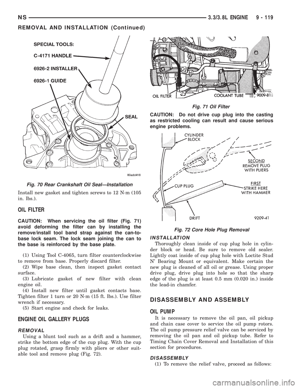
CAUTION: When servicing the oil filter (Fig. 71)
avoid deforming the filter can by installing the
remove/install tool band strap against the can-to-
base lock seam. The lock seam joining the can to
the base is reinforced by the base plate.
(1) Using Tool C-4065, turn filter counterclockwise
to remove from base. Properly discard filter.
(2) Wipe base clean, then inspect gasket contact
surface.
(3) Lubricate gasket of new filter with clean
engine oil.
(4) Install new filter until gasket contacts base.
Tighten filter 1 turn or 20 N┬┤m (15 ft. lbs.). Use filter
wrench if necessary.
(5) Start engine and check for leaks.
ENGINE OIL GALLERY PLUGS
REMOVAL
Using a blunt tool such as a drift and a hammer,
strike the bottom edge of the cup plug. With the cup
plug rotated, grasp firmly with pliers or other suit-
able tool and remove plug (Fig. 72).CAUTION: Do not drive cup plug into the casting
as restricted cooling can result and cause serious
engine problems.
INSTALLATION
Thoroughly clean inside of cup plug hole in cylin-
der block or head. Be sure to remove old sealer.
Lightly coat inside of cup plug hole with Loctite Stud
N' Bearing Mount or equivalent. Make certain the
new plug is cleaned of all oil or grease. Using proper
drive plug, drive plug into hole so that the sharp
edge of the plug is at least 0.5 mm (0.020 in.) inside
the lead-in chamfer.
DISASSEMBLY AND ASSEMBLY
OIL PUMP
It is necessary to remove the oil pan, oil pickup
and chain case cover to service the oil pump rotors.
The oil pump pressure relief valve can be serviced by
removing the oil pan and oil pickup tube. Refer to
Timing Chain Cover Removal and Installation of this
section for procedures.
DISASSEMBLY
(1) To remove the relief valve, proceed as follows:
Fig. 70 Rear Crankshaft Oil SealÐInstallation
Fig. 71 Oil Filter
Fig. 72 Core Hole Plug Removal
NS3.3/3.8L ENGINE 9 - 119
REMOVAL AND INSTALLATION (Continued)
Page 1194 of 1938

(14) Install crankshaft damper using M12-1.75 x
150 mm bolt, washer, thrust bearing and nut from
Special Tool 6792. Install crankshaft damper bolt and
tighten to 142 N┬┤m (105 ft. lbs.) (Fig. 39).
(15) Install accessory drive belts. Refer to Group 7,
Cooling System Accessory Drive section for proce-
dure.
(16) Perform camshaft and crankshaft timing
relearn. Refer to Group 25, Emission Control Sys-
tems for procedure.
TIMING BELTÐw/AUTO TENSIONERÐIF
EQUIPPED
CHECKING BELT TIMINGÐCOVER INSTALLED
┬▓Remove number one spark plug.
┬▓Using a dial indicator, set number one cylinder
to TDC on the compression stroke.
┬▓Remove the access plug from the outer timing
belt cover (Fig. 28).
┬▓Check the timing mark on the camshaft
sprocket, it should align with the arrow on the rear
belt cover (Fig. 29).
REMOVALÐTIMING BELT
(1) Remove accessory drive belts. Refer to Group 7,
Cooling System for procedure outlined in that sec-
tion.
(2) Raise vehicle on a hoist and remove right inner
splash shield (Fig. 42).
(3) Remove crankshaft damper bolt. Remove
damper using the large side of Special Tool 1026 and
insert 6827-A (Fig. 30).
(4) Lower vehicle and place a jack under engine.
(5) Remove right engine mount. Refer to procedure
outlined in this section.
(6) Remove right engine mount bracket (Fig. 44).
(7) Remove front timing belt cover (Fig. 31).CAUTION: Align camshaft and crankshaft timing
marks before removing the timing belt by rotating
the engine with the crankshaft.
(8) Inserta8mmAllen wrench into the belt ten-
sioner. Before rotating the tensioner insert the long
end of a 1/8┬║ or 3 mm Allen wrench into the pin hole
on the front of the tensioner (Fig. 33). Rotate the ten-
sioner counterclockwise with the Allen wrench, while
pushing in lightly on the 1/8 in. or 3 mm Allen
wrench, until it slides into the locking hole.
(9) Remove timing belt.
CAUTION: Do not rotate the camshafts once the
timing belt has been removed or damage to valve
components may occur.
CAMSHAFT AND CRANKSHAFT TIMING PROCEDURE AND
BELT INSTALLATION ÐSOHC ENGINE
(1) Set crankshaft sprocket to TDC by aligning the
sprocket with the arrow on the oil pump housing,
then back off to 3 notches before TDC (Fig. 35).
(2) Set camshaft to TDC by aligning mark on
sprocket with the arrow on the rear of timing belt
cover (Fig. 36).
(3) Move crankshaft to 1/2 mark before TDC (Fig.
37) for belt installation.
(4) Install timing belt. Starting at the crankshaft,
go around the water pump sprocket and then around
the camshaft sprocket.
(5) Move crankshaft sprocket to TDC to take up
belt slack.
(6) Remove the pin or 1/8┬║ or 3 mm Allen wrench
from belt tensioner.
(7) Rotate crankshaft 2 revolutions and check the
alignment of the timing marks (Fig. 50).
(8) Install front half of timing cover.
(9) Install engine mount bracket.
(10) Install Right engine mount. Refer to proce-
dure outlined in this section.
(11) Remove jack from under engine.
(12) Install crankshaft damper using M12-1.75 x
150 mm bolt, washer, thrust bearing and nut from
Special Tool 6792. Install crankshaft damper bolt and
tighten to 142 N┬┤m (105 ft. lbs.) (Fig. 39).
(13) Install accessory drive belts. Refer to Group 7,
Cooling System Accessory Drive section for proce-
dure.
(14) Raise vehicle on hoist and install right inner
splash shield.
(15) Perform camshaft and crankshaft timing
relearn procedure as follows:
┬▓Connect the DRB scan tool to the data link
(diagnostic) connector. This connector is located in
the passenger compartment; at the lower edge of
instrument panel; near the steering column.
Fig. 39 Crankshaft DamperÐInstallation
9 - 16 ENGINENS/GS
REMOVAL AND INSTALLATION (Continued)
Page 1202 of 1938
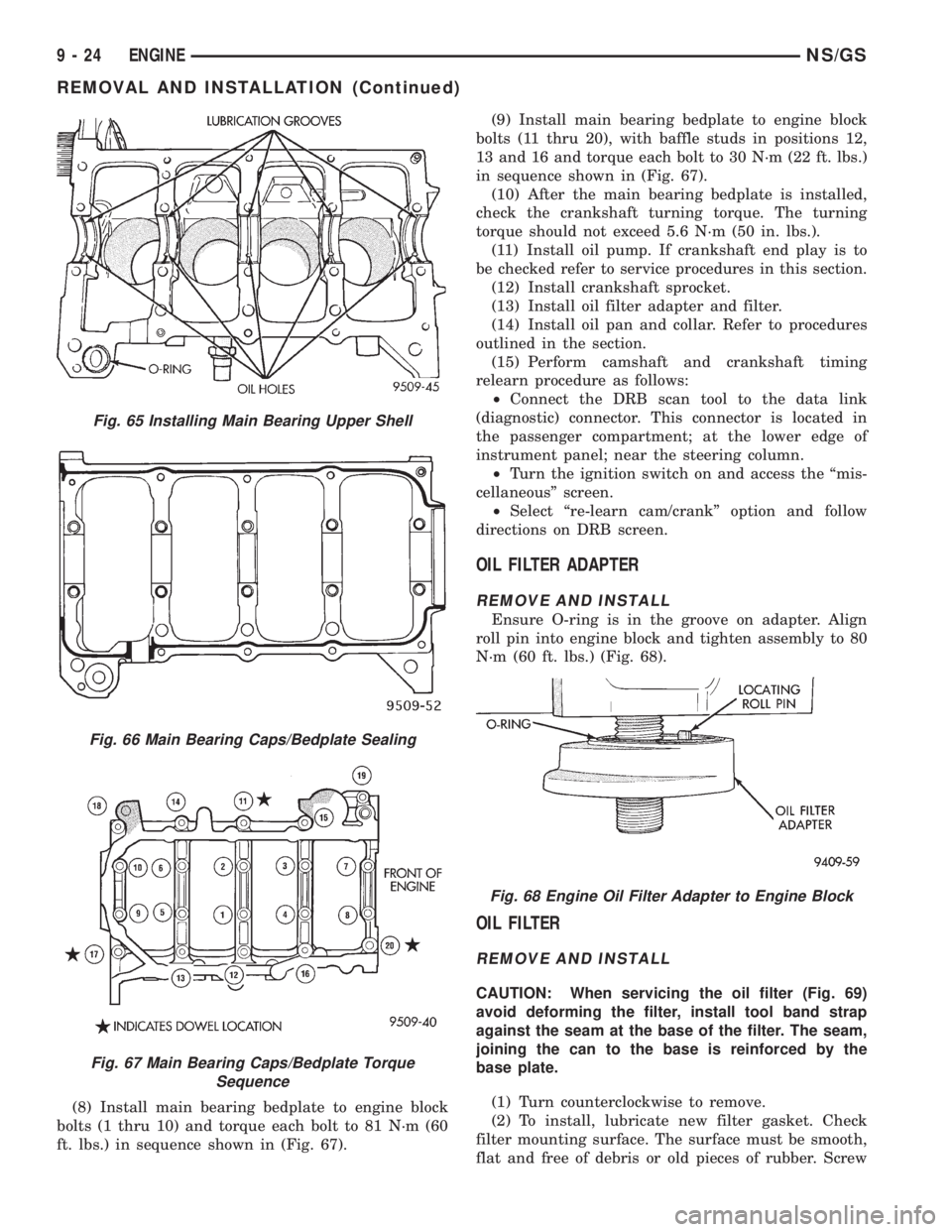
(8) Install main bearing bedplate to engine block
bolts (1 thru 10) and torque each bolt to 81 N┬┤m (60
ft. lbs.) in sequence shown in (Fig. 67).(9) Install main bearing bedplate to engine block
bolts (11 thru 20), with baffle studs in positions 12,
13 and 16 and torque each bolt to 30 N┬┤m (22 ft. lbs.)
in sequence shown in (Fig. 67).
(10) After the main bearing bedplate is installed,
check the crankshaft turning torque. The turning
torque should not exceed 5.6 N┬┤m (50 in. lbs.).
(11) Install oil pump. If crankshaft end play is to
be checked refer to service procedures in this section.
(12) Install crankshaft sprocket.
(13) Install oil filter adapter and filter.
(14) Install oil pan and collar. Refer to procedures
outlined in the section.
(15) Perform camshaft and crankshaft timing
relearn procedure as follows:
┬▓Connect the DRB scan tool to the data link
(diagnostic) connector. This connector is located in
the passenger compartment; at the lower edge of
instrument panel; near the steering column.
²Turn the ignition switch on and access the ªmis-
cellaneous┬║ screen.
²Select ªre-learn cam/crankº option and follow
directions on DRB screen.
OIL FILTER ADAPTER
REMOVE AND INSTALL
Ensure O-ring is in the groove on adapter. Align
roll pin into engine block and tighten assembly to 80
N┬┤m (60 ft. lbs.) (Fig. 68).
OIL FILTER
REMOVE AND INSTALL
CAUTION: When servicing the oil filter (Fig. 69)
avoid deforming the filter, install tool band strap
against the seam at the base of the filter. The seam,
joining the can to the base is reinforced by the
base plate.
(1) Turn counterclockwise to remove.
(2) To install, lubricate new filter gasket. Check
filter mounting surface. The surface must be smooth,
flat and free of debris or old pieces of rubber. Screw
Fig. 65 Installing Main Bearing Upper Shell
Fig. 66 Main Bearing Caps/Bedplate Sealing
Fig. 67 Main Bearing Caps/Bedplate Torque
Sequence
Fig. 68 Engine Oil Filter Adapter to Engine Block
9 - 24 ENGINENS/GS
REMOVAL AND INSTALLATION (Continued)
Page 1219 of 1938
Type ........................425CLIEE (36B)
Lubrication . Pressure Lubrication by Rotary Pump,
Full-Flow Filtration
Engine Rotation....Clockwise Viewed From Front
Cover
ENGINE IDENTIFICATION
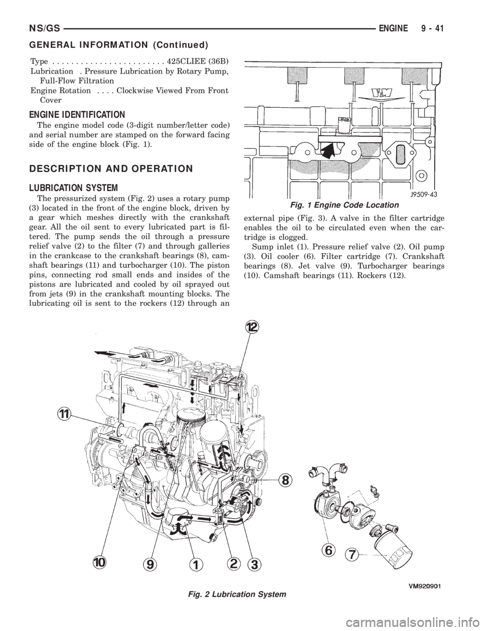
The engine model code (3-digit number/letter code)
and serial number are stamped on the forward facing
side of the engine block (Fig. 1).
DESCRIPTION AND OPERATION
LUBRICATION SYSTEM
The pressurized system (Fig. 2) uses a rotary pump
(3) located in the front of the engine block, driven by
a gear which meshes directly with the crankshaft
gear. All the oil sent to every lubricated part is fil-
tered. The pump sends the oil through a pressure
relief valve (2) to the filter (7) and through galleries
in the crankcase to the crankshaft bearings (8), cam-
shaft bearings (11) and turbocharger (10). The piston
pins, connecting rod small ends and insides of the
pistons are lubricated and cooled by oil sprayed out
from jets (9) in the crankshaft mounting blocks. The
lubricating oil is sent to the rockers (12) through anexternal pipe (Fig. 3). A valve in the filter cartridge
enables the oil to be circulated even when the car-
tridge is clogged.
Sump inlet (1). Pressure relief valve (2). Oil pump
(3). Oil cooler (6). Filter cartridge (7). Crankshaft
bearings (8). Jet valve (9). Turbocharger bearings
(10). Camshaft bearings (11). Rockers (12).
Fig. 2 Lubrication System
Fig. 1 Engine Code Location
NS/GSENGINE 9 - 41
GENERAL INFORMATION (Continued)
Page 1226 of 1938
ENGINE OIL CHANGE
WARNING: NEW OR USED ENGINE OIL CAN BE
IRRITATING TO THE SKIN. AVOID PROLONGED OR
REPEATED SKIN CONTACT WITH ENGINE OIL.
CONTAMINANTS IN USED ENGINE OIL, CAUSED BY
INTERNAL COMBUSTION, CAN BE HAZARDOUS TO
YOUR HEALTH. THOROUGHLY WASH EXPOSED
SKIN WITH SOAP AND WATER. DO NOT WASH
SKIN WITH GASOLINE, DIESEL FUEL, THINNER, OR
SOLVENTS, HEALTH PROBLEMS CAN RESULT. DO
NOT POLLUTE, DISPOSE OF USED ENGINE OIL
PROPERLY. CONTACT YOUR DEALER OR GOVERN-
MENT AGENCY FOR LOCATION OF COLLECTION
CENTER IN YOUR AREA.
Run engine until achieving normal operating tem-
perature.
(1) Position the vehicle on a level surface and turn
engine off.
(2) Remove oil fill cap.
(3) Hoist vehicle. Refer to Hoisting and Jacking
Recommendations.
(4) Place a suitable drain pan under crankcase
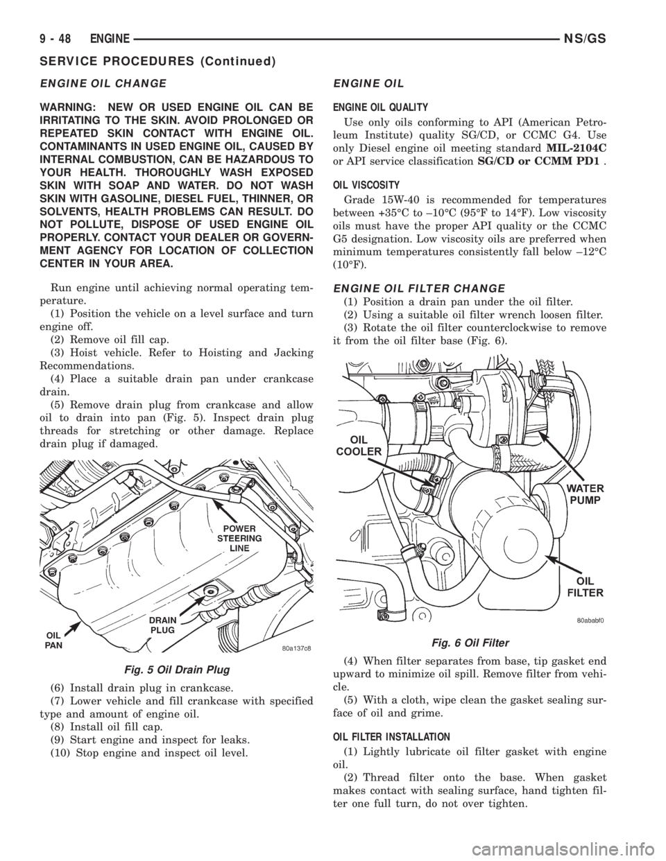
drain.
(5) Remove drain plug from crankcase and allow
oil to drain into pan (Fig. 5). Inspect drain plug
threads for stretching or other damage. Replace
drain plug if damaged.
(6) Install drain plug in crankcase.
(7) Lower vehicle and fill crankcase with specified
type and amount of engine oil.
(8) Install oil fill cap.
(9) Start engine and inspect for leaks.
(10) Stop engine and inspect oil level.
ENGINE OIL
ENGINE OIL QUALITY
Use only oils conforming to API (American Petro-
leum Institute) quality SG/CD, or CCMC G4. Use
only Diesel engine oil meeting standardMIL-2104C
or API service classificationSG/CD or CCMM PD1.
OIL VISCOSITY
Grade 15W-40 is recommended for temperatures
between +35ÉC to ±10ÉC (95ÉF to 14ÉF). Low viscosity
oils must have the proper API quality or the CCMC
G5 designation. Low viscosity oils are preferred when
minimum temperatures consistently fall below ±12ÉC
(10ÉF).
ENGINE OIL FILTER CHANGE
(1) Position a drain pan under the oil filter.
(2) Using a suitable oil filter wrench loosen filter.
(3) Rotate the oil filter counterclockwise to remove
it from the oil filter base (Fig. 6).
(4) When filter separates from base, tip gasket end
upward to minimize oil spill. Remove filter from vehi-
cle.
(5) With a cloth, wipe clean the gasket sealing sur-
face of oil and grime.
OIL FILTER INSTALLATION
(1) Lightly lubricate oil filter gasket with engine
oil.
(2) Thread filter onto the base. When gasket
makes contact with sealing surface, hand tighten fil-
ter one full turn, do not over tighten.
Fig. 5 Oil Drain Plug
Fig. 6 Oil Filter
9 - 48 ENGINENS/GS
SERVICE PROCEDURES (Continued)
Page 1283 of 1938
FRAME
INDEX
page page
REMOVAL AND INSTALLATION
FRONT CROSSMEMBER MOUNT BUSHINGS . . . 5
FRONT CROSSMEMBER................... 3SPECIFICATIONS
FRAME AND BODY OPENING DIMENSIONS.... 5
REMOVAL AND INSTALLATION
FRONT CROSSMEMBER
The front suspension crossmember must be
installed in the design location to achieve proper
front end suspension alignment. If the crossmember
is removed without applying reference marks on the
frame rails, align the crossmember according to the
dimensions provided in this group.
NOTE: If the caged nuts in the frame rails become
damaged and cannot be reused, a replacement nut
can be obtained through a MoparTParts supplier.
REMOVAL
(1) Disconnect battery negative cable.
(2) Remove steering column lower cover from
instrument panel. Refer to Group 8E, Instrument
Panel and Systems.
(3) Remove knee blocker reinforcement. Refer to
Group 8E, Instrument Panel and Systems.
(4) Position steering so front wheels are straight
ahead.
CAUTION: Do not rotate steering wheel after disen-
gaging lower coupling from steering gear, damage
to airbag clock spring can result.
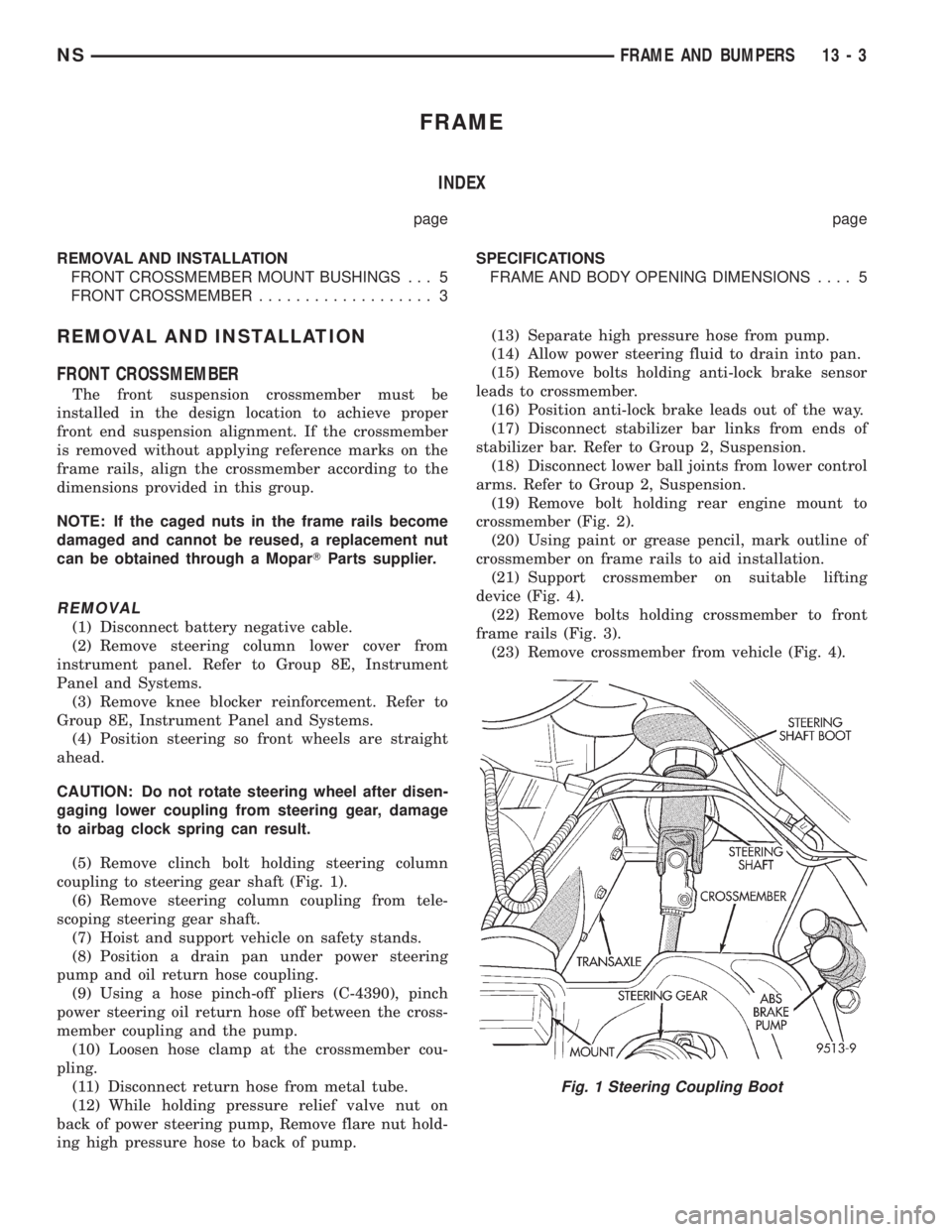
(5) Remove clinch bolt holding steering column
coupling to steering gear shaft (Fig. 1).
(6) Remove steering column coupling from tele-
scoping steering gear shaft.
(7) Hoist and support vehicle on safety stands.
(8) Position a drain pan under power steering
pump and oil return hose coupling.
(9) Using a hose pinch-off pliers (C-4390), pinch
power steering oil return hose off between the cross-
member coupling and the pump.
(10) Loosen hose clamp at the crossmember cou-
pling.
(11) Disconnect return hose from metal tube.
(12) While holding pressure relief valve nut on
back of power steering pump, Remove flare nut hold-
ing high pressure hose to back of pump.(13) Separate high pressure hose from pump.
(14) Allow power steering fluid to drain into pan.
(15) Remove bolts holding anti-lock brake sensor
leads to crossmember.
(16) Position anti-lock brake leads out of the way.
(17) Disconnect stabilizer bar links from ends of
stabilizer bar. Refer to Group 2, Suspension.
(18) Disconnect lower ball joints from lower control
arms. Refer to Group 2, Suspension.
(19) Remove bolt holding rear engine mount to
crossmember (Fig. 2).
(20) Using paint or grease pencil, mark outline of
crossmember on frame rails to aid installation.
(21) Support crossmember on suitable lifting
device (Fig. 4).
(22) Remove bolts holding crossmember to front
frame rails (Fig. 3).
(23) Remove crossmember from vehicle (Fig. 4).
Fig. 1 Steering Coupling Boot
NSFRAME AND BUMPERS 13 - 3
Page 1308 of 1938
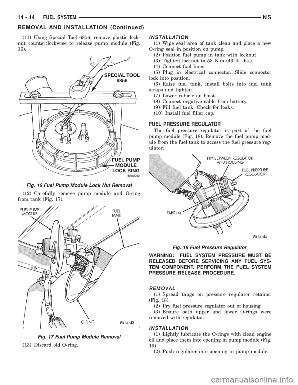
(11) Using Special Tool 6856, remove plastic lock-
nut counterclockwise to release pump module (Fig.
16).
(12) Carefully remove pump module and O-ring
from tank (Fig. 17).
(13) Discard old O-ring.INSTALLATION
(1) Wipe seal area of tank clean and place a new
O-ring seal in position on pump.
(2) Position fuel pump in tank with locknut.
(3) Tighten locknut to 53 N┬┤m (43 ft. lbs.).
(4) Connect fuel lines.
(5) Plug in electrical connector. Slide connector
lock into position.
(6) Raise fuel tank, install bolts into fuel tank
straps and tighten.
(7) Lower vehicle on hoist.
(8) Connect negative cable from battery.
(9) Fill fuel tank. Check for leaks.
(10) Install fuel filler cap.
FUEL PRESSURE REGULATOR
The fuel pressure regulator is part of the fuel
pump module (Fig. 18). Remove the fuel pump mod-
ule from the fuel tank to access the fuel pressure reg-
ulator.
WARNING: FUEL SYSTEM PRESSURE MUST BE
RELEASED BEFORE SERVICING ANY FUEL SYS-
TEM COMPONENT. PERFORM THE FUEL SYSTEM
PRESSURE RELEASE PROCEDURE.
REMOVAL
(1) Spread tangs on pressure regulator retainer
(Fig. 18).
(2) Pry fuel pressure regulator out of housing.
(3) Ensure both upper and lower O-rings were
removed with regulator.
INSTALLATION
(1) Lightly lubricate the O-rings with clean engine
oil and place them into opening in pump module (Fig.
19).
(2) Push regulator into opening in pump module.
Fig. 16 Fuel Pump Module Lock Nut Removal
Fig. 17 Fuel Pump Module Removal
Fig. 18 Fuel Pressure Regulator
14 - 14 FUEL SYSTEMNS
REMOVAL AND INSTALLATION (Continued)
Page 1388 of 1938

(8) Disconnect the main engine wiring harness
from the glow plugs.
(9) Disconnect the four high┬▒pressure fuel lines
from the fuel injection pump. Also disconnect fuel
lines at the fuel injectors. For procedures, refer to
High┬▒Pressure Fuel Lines in this group. Place a rag
beneath the fittings to catch excess fuel.
(10) Remove plug from timing gear cover.
(11) The ªTop Dead Centerº (TDC) compression fir-
ing stroke must be determined as follows:
(a) Remove the valve cover, refer to Group 9,
Valve Cover Removal/Installation.
(b) Remove the right front tire and splash
shield. Using a socket attached to the end of crank-
shaft, rotate the engine (counterÐclockwise as
viewed from front).
(c) Rotate the engine until cylinder #4 rockers
are in between movement.
(d) Remove rocker arm assembly.
(e) Remove valve spring and keepers.CAU-
TION: When the piston is at TDC there is only
2 mm (.080 thousand) clearance between the
valve and piston.
(f) Let the valve set on top of piston. Install a
dial indicator to the top of the valve stem.
(g) Rotate engine back and forth to find the TDC
position with the indicator on the valve stem. Mark
the damper and timing cover for TDC.
NOTE: On later model 1997 engines, a hole in the
bottom of the clutch housing can be lined up with a
hole in the flywheel, allowing the engine to be held
at TDC with a special alignment tool, part # VM1035.(12) Remove injection pump drive gear nut (Fig.
41) and washer.CAUTION: Be very careful not to
drop the washer into the timing gear cover.
(13) A special 3┬▒piece gear removal tool set
VM.1003 (Fig. 42) must be used to remove the injec-
tion pump drive gear from the pump shaft.
(a) Thread the adapter (Fig. 43) into the timing
cover.
(b) Thread the gear puller into the injection
pump drive gear (Fig. 43). This tool is also used to
hold the gear in synchronization during pump
removal.
(c) Remove the three injection pump┬▒to┬▒gear
cover mounting nuts (Fig. 44).CAUTION: This
step must be done to prevent breakage of the
Fig. 40 Engine Coolant Temperature Sensor
Fig. 41 Removing Pump Drive Gear Nut
Fig. 42 Pump Gear Tools
14 - 20 FUEL SYSTEMÐ2.5L DIESEL ENGINE/2.0L GAS ENGINENS/GS
REMOVAL AND INSTALLATION (Continued)