CHRYSLER VOYAGER 1996 Service Manual
VOYAGER 1996
CHRYSLER
CHRYSLER
https://www.carmanualsonline.info/img/25/56867/w960_56867-0.png
CHRYSLER VOYAGER 1996 Service Manual
Trending: brake sensor, fuel pump, Security, child restraint, ignition, refrigerant type, tire type
Page 1591 of 1938
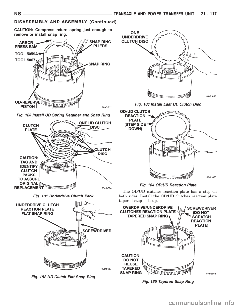
CAUTION: Compress return spring just enough to
remove or install snap ring.
The OD/UD clutches reaction plate has a step on
both sides. Install the OD/UD clutches reaction plate
tapered step side up.
Fig. 180 Install UD Spring Retainer and Snap Ring
Fig. 181 Underdrive Clutch Pack
Fig. 182 UD Clutch Flat Snap Ring
Fig. 183 Install Last UD Clutch Disc
Fig. 184 OD/UD Reaction Plate
Fig. 185 Tapered Snap Ring
NSTRANSAXLE AND POWER TRANSFER UNIT 21 - 117
DISASSEMBLY AND ASSEMBLY (Continued)
Page 1592 of 1938
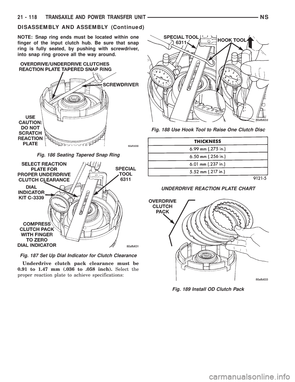
NOTE: Snap ring ends must be located within one
finger of the input clutch hub. Be sure that snap
ring is fully seated, by pushing with screwdriver,
into snap ring groove all the way around.
Underdrive clutch pack clearance must be
0.91 to 1.47 mm (.036 to .058 inch).Select the
proper reaction plate to achieve specifications:
Fig. 186 Seating Tapered Snap Ring
Fig. 187 Set Up Dial Indicator for Clutch Clearance
Fig. 188 Use Hook Tool to Raise One Clutch Disc
UNDERDRIVE REACTION PLATE CHART
Fig. 189 Install OD Clutch Pack
21 - 118 TRANSAXLE AND POWER TRANSFER UNITNS
DISASSEMBLY AND ASSEMBLY (Continued)
Page 1593 of 1938
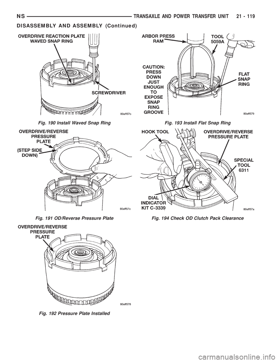
Fig. 190 Install Waved Snap Ring
Fig. 191 OD/Reverse Pressure Plate
Fig. 192 Pressure Plate Installed
Fig. 193 Install Flat Snap Ring
Fig. 194 Check OD Clutch Pack Clearance
NSTRANSAXLE AND POWER TRANSFER UNIT 21 - 119
DISASSEMBLY AND ASSEMBLY (Continued)
Page 1594 of 1938
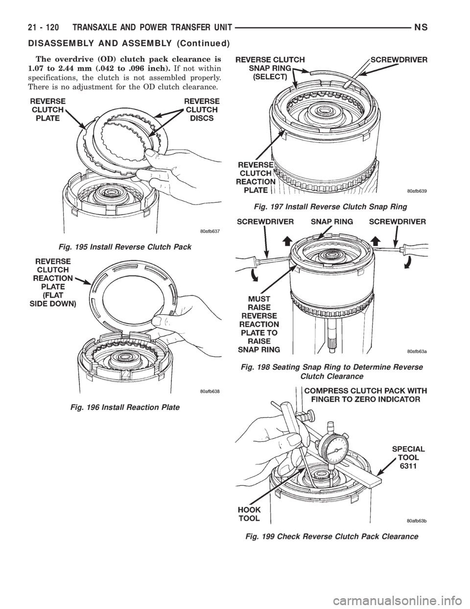
The overdrive (OD) clutch pack clearance is
1.07 to 2.44 mm (.042 to .096 inch).If not within
specifications, the clutch is not assembled properly.
There is no adjustment for the OD clutch clearance.
Fig. 195 Install Reverse Clutch Pack
Fig. 196 Install Reaction Plate
Fig. 197 Install Reverse Clutch Snap Ring
Fig. 198 Seating Snap Ring to Determine Reverse
Clutch Clearance
Fig. 199 Check Reverse Clutch Pack Clearance
21 - 120 TRANSAXLE AND POWER TRANSFER UNITNS
DISASSEMBLY AND ASSEMBLY (Continued)
Page 1595 of 1938
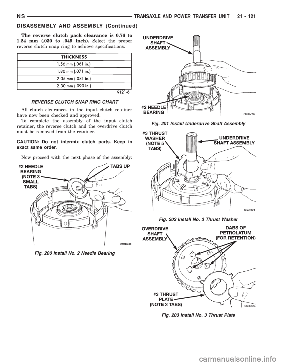
The reverse clutch pack clearance is 0.76 to
1.24 mm (.030 to .049 inch).Select the proper
reverse clutch snap ring to achieve specifications:
All clutch clearances in the input clutch retainer
have now been checked and approved.
To complete the assembly of the input clutch
retainer, the reverse clutch and the overdrive clutch
must be removed from the retainer.
CAUTION: Do not intermix clutch parts. Keep in
exact same order.
Now proceed with the next phase of the assembly:
REVERSE CLUTCH SNAP RING CHART
Fig. 200 Install No. 2 Needle Bearing
Fig. 201 Install Underdrive Shaft Assembly
Fig. 202 Install No. 3 Thrust Washer
Fig. 203 Install No. 3 Thrust Plate
NSTRANSAXLE AND POWER TRANSFER UNIT 21 - 121
DISASSEMBLY AND ASSEMBLY (Continued)
Page 1596 of 1938
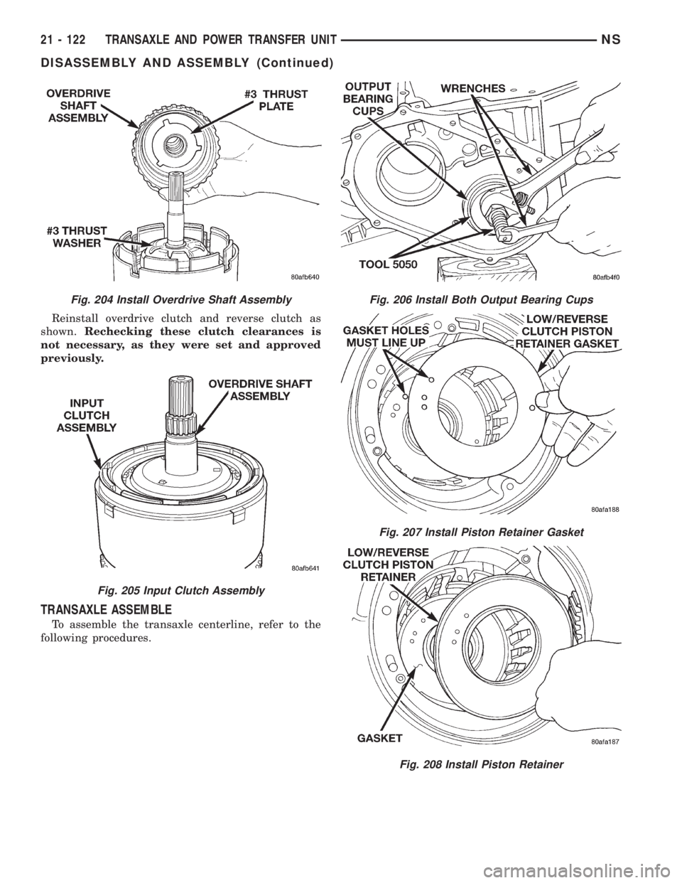
Reinstall overdrive clutch and reverse clutch as
shown.Rechecking these clutch clearances is
not necessary, as they were set and approved
previously.
TRANSAXLE ASSEMBLE
To assemble the transaxle centerline, refer to the
following procedures.
Fig. 204 Install Overdrive Shaft Assembly
Fig. 205 Input Clutch Assembly
Fig. 206 Install Both Output Bearing Cups
Fig. 207 Install Piston Retainer Gasket
Fig. 208 Install Piston Retainer
21 - 122 TRANSAXLE AND POWER TRANSFER UNITNS
DISASSEMBLY AND ASSEMBLY (Continued)
Page 1597 of 1938
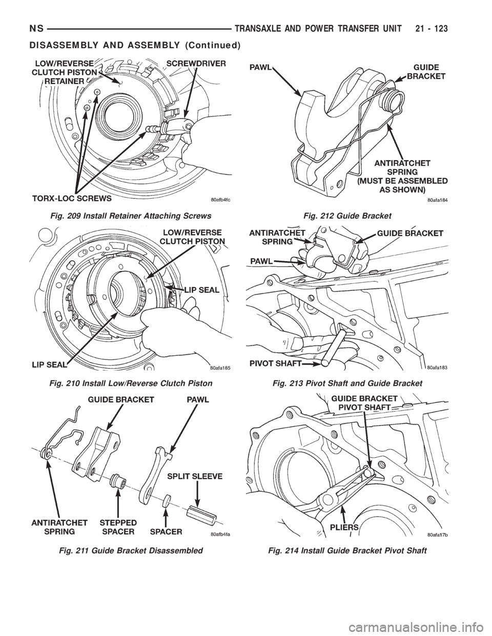
Fig. 209 Install Retainer Attaching Screws
Fig. 210 Install Low/Reverse Clutch Piston
Fig. 211 Guide Bracket Disassembled
Fig. 212 Guide Bracket
Fig. 213 Pivot Shaft and Guide Bracket
Fig. 214 Install Guide Bracket Pivot Shaft
NSTRANSAXLE AND POWER TRANSFER UNIT 21 - 123
DISASSEMBLY AND ASSEMBLY (Continued)
Page 1598 of 1938
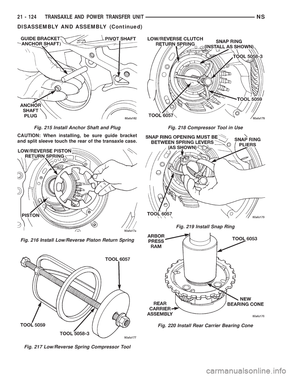
CAUTION: When installing, be sure guide bracket
and split sleeve touch the rear of the transaxle case.
Fig. 215 Install Anchor Shaft and Plug
Fig. 216 Install Low/Reverse Piston Return Spring
Fig. 217 Low/Reverse Spring Compressor Tool
Fig. 218 Compressor Tool in Use
Fig. 219 Install Snap Ring
Fig. 220 Install Rear Carrier Bearing Cone
21 - 124 TRANSAXLE AND POWER TRANSFER UNITNS
DISASSEMBLY AND ASSEMBLY (Continued)
Page 1599 of 1938
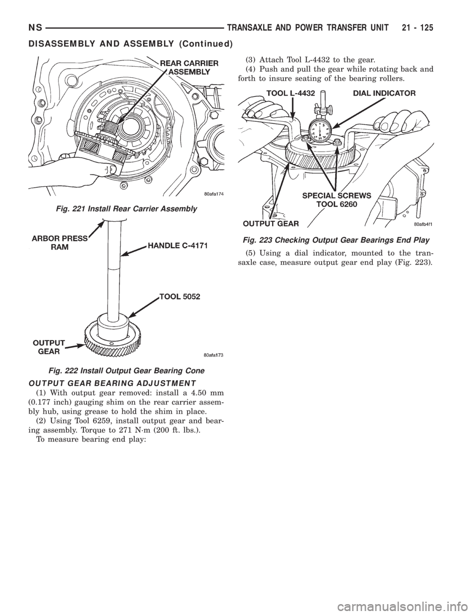
OUTPUT GEAR BEARING ADJUSTMENT
(1) With output gear removed: install a 4.50 mm
(0.177 inch) gauging shim on the rear carrier assem-
bly hub, using grease to hold the shim in place.
(2) Using Tool 6259, install output gear and bear-
ing assembly. Torque to 271 N´m (200 ft. lbs.).
To measure bearing end play:(3) Attach Tool L-4432 to the gear.
(4) Push and pull the gear while rotating back and
forth to insure seating of the bearing rollers.
(5) Using a dial indicator, mounted to the tran-
saxle case, measure output gear end play (Fig. 223).
Fig. 221 Install Rear Carrier Assembly
Fig. 222 Install Output Gear Bearing Cone
Fig. 223 Checking Output Gear Bearings End Play
NSTRANSAXLE AND POWER TRANSFER UNIT 21 - 125
DISASSEMBLY AND ASSEMBLY (Continued)
Page 1600 of 1938
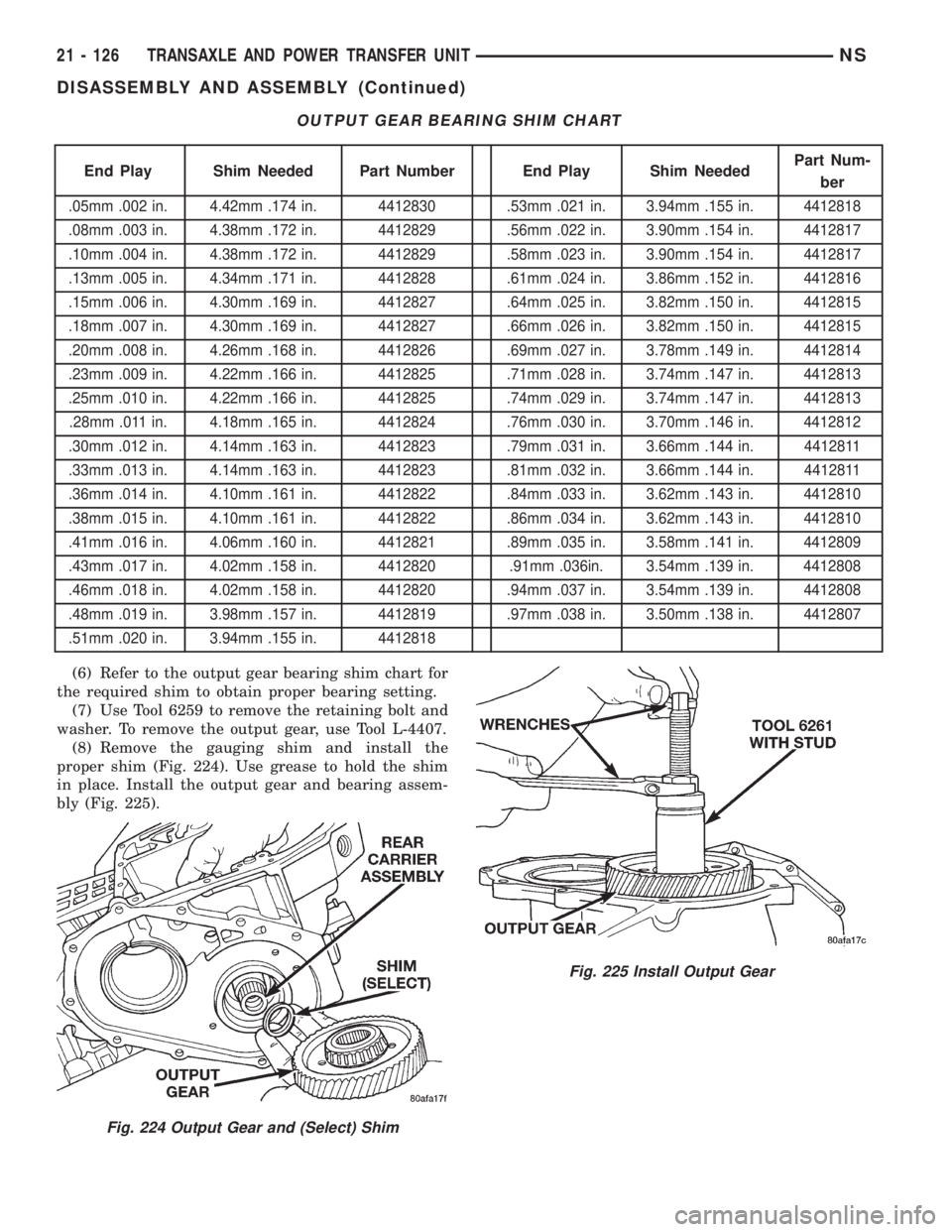
(6) Refer to the output gear bearing shim chart for
the required shim to obtain proper bearing setting.
(7) Use Tool 6259 to remove the retaining bolt and
washer. To remove the output gear, use Tool L-4407.
(8) Remove the gauging shim and install the
proper shim (Fig. 224). Use grease to hold the shim
in place. Install the output gear and bearing assem-
bly (Fig. 225).
OUTPUT GEAR BEARING SHIM CHART
End Play Shim Needed Part Number End Play Shim NeededPart Num-
ber
.05mm .002 in. 4.42mm .174 in. 4412830 .53mm .021 in. 3.94mm .155 in. 4412818
.08mm .003 in. 4.38mm .172 in. 4412829 .56mm .022 in. 3.90mm .154 in. 4412817
.10mm .004 in. 4.38mm .172 in. 4412829 .58mm .023 in. 3.90mm .154 in. 4412817
.13mm .005 in. 4.34mm .171 in. 4412828 .61mm .024 in. 3.86mm .152 in. 4412816
.15mm .006 in. 4.30mm .169 in. 4412827 .64mm .025 in. 3.82mm .150 in. 4412815
.18mm .007 in. 4.30mm .169 in. 4412827 .66mm .026 in. 3.82mm .150 in. 4412815
.20mm .008 in. 4.26mm .168 in. 4412826 .69mm .027 in. 3.78mm .149 in. 4412814
.23mm .009 in. 4.22mm .166 in. 4412825 .71mm .028 in. 3.74mm .147 in. 4412813
.25mm .010 in. 4.22mm .166 in. 4412825 .74mm .029 in. 3.74mm .147 in. 4412813
.28mm .011 in. 4.18mm .165 in. 4412824 .76mm .030 in. 3.70mm .146 in. 4412812
.30mm .012 in. 4.14mm .163 in. 4412823 .79mm .031 in. 3.66mm .144 in. 4412811
.33mm .013 in. 4.14mm .163 in. 4412823 .81mm .032 in. 3.66mm .144 in. 4412811
.36mm .014 in. 4.10mm .161 in. 4412822 .84mm .033 in. 3.62mm .143 in. 4412810
.38mm .015 in. 4.10mm .161 in. 4412822 .86mm .034 in. 3.62mm .143 in. 4412810
.41mm .016 in. 4.06mm .160 in. 4412821 .89mm .035 in. 3.58mm .141 in. 4412809
.43mm .017 in. 4.02mm .158 in. 4412820 .91mm .036in. 3.54mm .139 in. 4412808
.46mm .018 in. 4.02mm .158 in. 4412820 .94mm .037 in. 3.54mm .139 in. 4412808
.48mm .019 in. 3.98mm .157 in. 4412819 .97mm .038 in. 3.50mm .138 in. 4412807
.51mm .020 in. 3.94mm .155 in. 4412818
Fig. 224 Output Gear and (Select) Shim
Fig. 225 Install Output Gear
21 - 126 TRANSAXLE AND POWER TRANSFER UNITNS
DISASSEMBLY AND ASSEMBLY (Continued)
Trending: key, engine overheat, window, battery location, seats, center console, instrument panel
