CHRYSLER VOYAGER 1996 Service Manual
Manufacturer: CHRYSLER, Model Year: 1996, Model line: VOYAGER, Model: CHRYSLER VOYAGER 1996Pages: 1938, PDF Size: 55.84 MB
Page 1561 of 1938
TRANSMISSION CONTROL MODULE
Do not interchange Transmission Control Modules
with previous year transmission control modules. If a
same year TCM is being used from a different vehi-
cle, the following procedures must be performed:
²Quick Learn Procedure
²Electronic Pinion Procedure
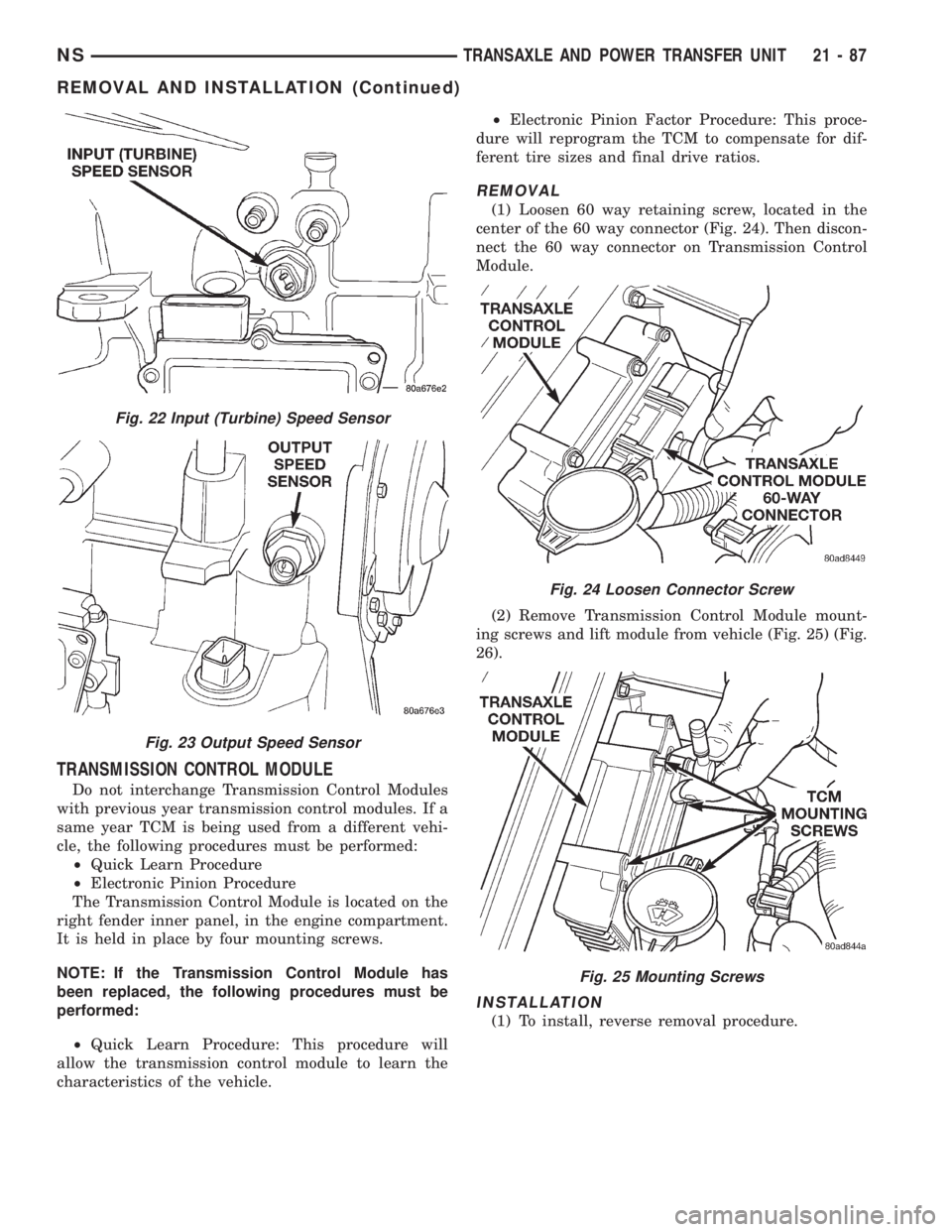
The Transmission Control Module is located on the
right fender inner panel, in the engine compartment.
It is held in place by four mounting screws.
NOTE: If the Transmission Control Module has
been replaced, the following procedures must be
performed:
²Quick Learn Procedure: This procedure will
allow the transmission control module to learn the
characteristics of the vehicle.²Electronic Pinion Factor Procedure: This proce-
dure will reprogram the TCM to compensate for dif-
ferent tire sizes and final drive ratios.
REMOVAL
(1) Loosen 60 way retaining screw, located in the
center of the 60 way connector (Fig. 24). Then discon-
nect the 60 way connector on Transmission Control
Module.
(2) Remove Transmission Control Module mount-
ing screws and lift module from vehicle (Fig. 25) (Fig.
26).
INSTALLATION
(1) To install, reverse removal procedure.
Fig. 22 Input (Turbine) Speed Sensor
Fig. 23 Output Speed Sensor
Fig. 24 Loosen Connector Screw
Fig. 25 Mounting Screws
NSTRANSAXLE AND POWER TRANSFER UNIT 21 - 87
REMOVAL AND INSTALLATION (Continued)
Page 1562 of 1938
VALVE BODY
REMOVAL
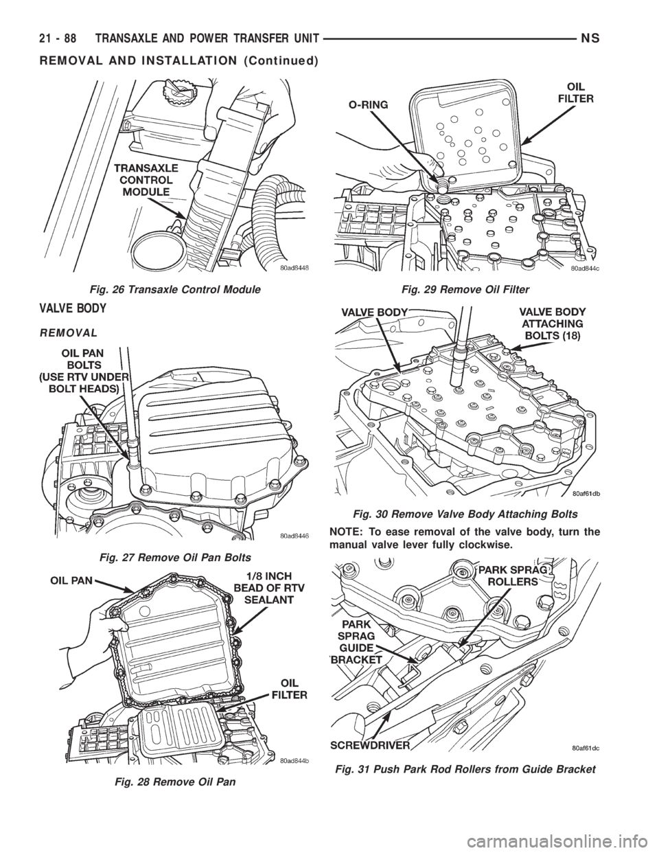
NOTE: To ease removal of the valve body, turn the
manual valve lever fully clockwise.
Fig. 26 Transaxle Control Module
Fig. 27 Remove Oil Pan Bolts
Fig. 28 Remove Oil Pan
Fig. 29 Remove Oil Filter
Fig. 30 Remove Valve Body Attaching Bolts
Fig. 31 Push Park Rod Rollers from Guide Bracket
21 - 88 TRANSAXLE AND POWER TRANSFER UNITNS
REMOVAL AND INSTALLATION (Continued)
Page 1563 of 1938
INSTALLATION
To install valve body, reverse removal procedure
CAUTION: The valve body manual shaft pilot may
distort and bind the manual valve if the valve body
is mishandled or dropped.
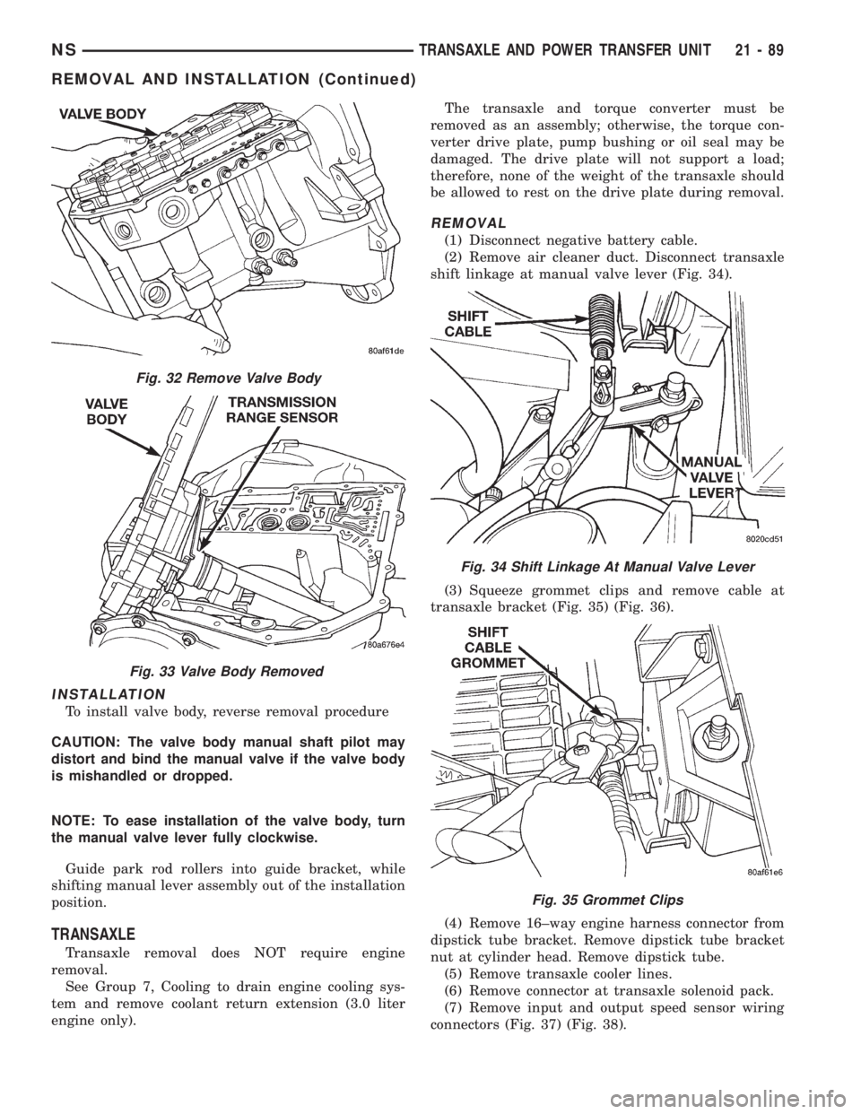
NOTE: To ease installation of the valve body, turn
the manual valve lever fully clockwise.
Guide park rod rollers into guide bracket, while
shifting manual lever assembly out of the installation
position.
TRANSAXLE
Transaxle removal does NOT require engine
removal.
See Group 7, Cooling to drain engine cooling sys-
tem and remove coolant return extension (3.0 liter
engine only).The transaxle and torque converter must be
removed as an assembly; otherwise, the torque con-
verter drive plate, pump bushing or oil seal may be
damaged. The drive plate will not support a load;
therefore, none of the weight of the transaxle should
be allowed to rest on the drive plate during removal.
REMOVAL
(1) Disconnect negative battery cable.
(2) Remove air cleaner duct. Disconnect transaxle
shift linkage at manual valve lever (Fig. 34).
(3) Squeeze grommet clips and remove cable at
transaxle bracket (Fig. 35) (Fig. 36).
(4) Remove 16±way engine harness connector from
dipstick tube bracket. Remove dipstick tube bracket
nut at cylinder head. Remove dipstick tube.
(5) Remove transaxle cooler lines.
(6) Remove connector at transaxle solenoid pack.
(7) Remove input and output speed sensor wiring
connectors (Fig. 37) (Fig. 38).
Fig. 32 Remove Valve Body
Fig. 33 Valve Body Removed
Fig. 34 Shift Linkage At Manual Valve Lever
Fig. 35 Grommet Clips
NSTRANSAXLE AND POWER TRANSFER UNIT 21 - 89
REMOVAL AND INSTALLATION (Continued)
Page 1564 of 1938
(8) Disconnect electrical connector at transmission
range sensor.
(9) Remove upper bellhousing upper bolts.
(10) Remove heater tube mounting bolt.(11) Remove vehicle speed sensor wiring at sensor.
(12) Remove one rear engine mount bolt from top.
(13) Remove rear engine mount shield screw.
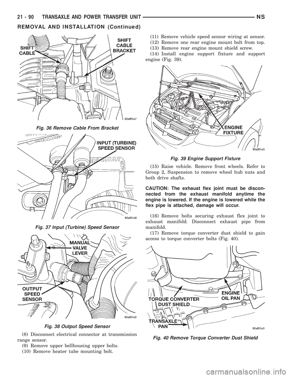
(14) Install engine support fixture and support
engine (Fig. 39).
(15) Raise vehicle. Remove front wheels. Refer to
Group 2, Suspension to remove wheel hub nuts and
both drive shafts.
CAUTION: The exhaust flex joint must be discon-
nected from the exhaust manifold anytime the
engine is lowered. If the engine is lowered while the
flex pipe is attached, damage will occur.
(16) Remove bolts securing exhaust flex joint to
exhaust manifold. Disconnect exhaust pipe from
manifold.
(17) Remove torque converter dust shield to gain
access to torque converter bolts (Fig. 40).
Fig. 36 Remove Cable From Bracket
Fig. 37 Input (Turbine) Speed Sensor
Fig. 38 Output Speed Sensor
Fig. 39 Engine Support Fixture
Fig. 40 Remove Torque Converter Dust Shield
21 - 90 TRANSAXLE AND POWER TRANSFER UNITNS
REMOVAL AND INSTALLATION (Continued)
Page 1565 of 1938
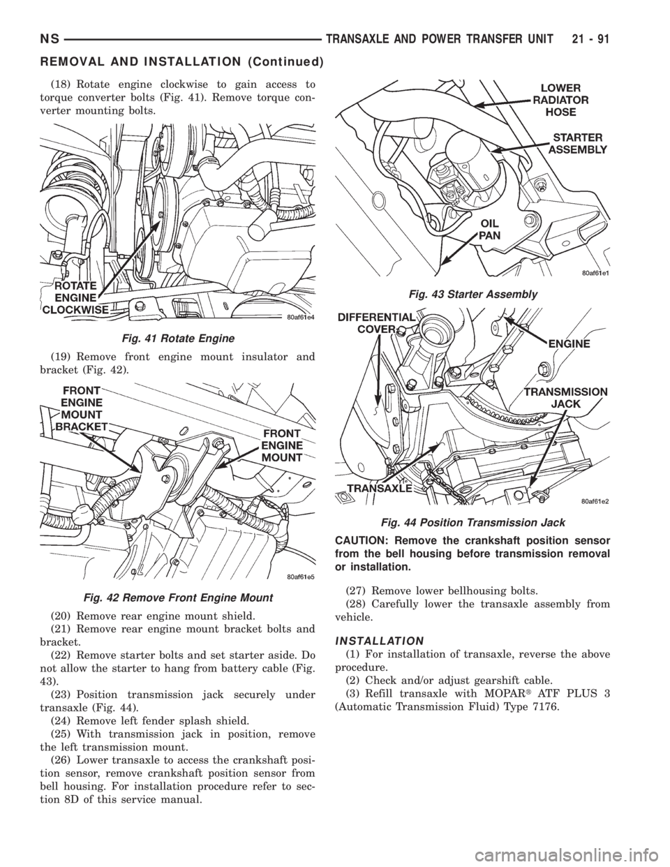
(18) Rotate engine clockwise to gain access to
torque converter bolts (Fig. 41). Remove torque con-
verter mounting bolts.
(19) Remove front engine mount insulator and
bracket (Fig. 42).
(20) Remove rear engine mount shield.
(21) Remove rear engine mount bracket bolts and
bracket.
(22) Remove starter bolts and set starter aside. Do
not allow the starter to hang from battery cable (Fig.
43).
(23) Position transmission jack securely under
transaxle (Fig. 44).
(24) Remove left fender splash shield.
(25) With transmission jack in position, remove
the left transmission mount.
(26) Lower transaxle to access the crankshaft posi-
tion sensor, remove crankshaft position sensor from
bell housing. For installation procedure refer to sec-
tion 8D of this service manual.CAUTION: Remove the crankshaft position sensor
from the bell housing before transmission removal
or installation.
(27) Remove lower bellhousing bolts.
(28) Carefully lower the transaxle assembly from
vehicle.
INSTALLATION
(1) For installation of transaxle, reverse the above
procedure.
(2) Check and/or adjust gearshift cable.
(3) Refill transaxle with MOPARtATF PLUS 3
(Automatic Transmission Fluid) Type 7176.
Fig. 41 Rotate Engine
Fig. 42 Remove Front Engine Mount
Fig. 43 Starter Assembly
Fig. 44 Position Transmission Jack
NSTRANSAXLE AND POWER TRANSFER UNIT 21 - 91
REMOVAL AND INSTALLATION (Continued)
Page 1566 of 1938
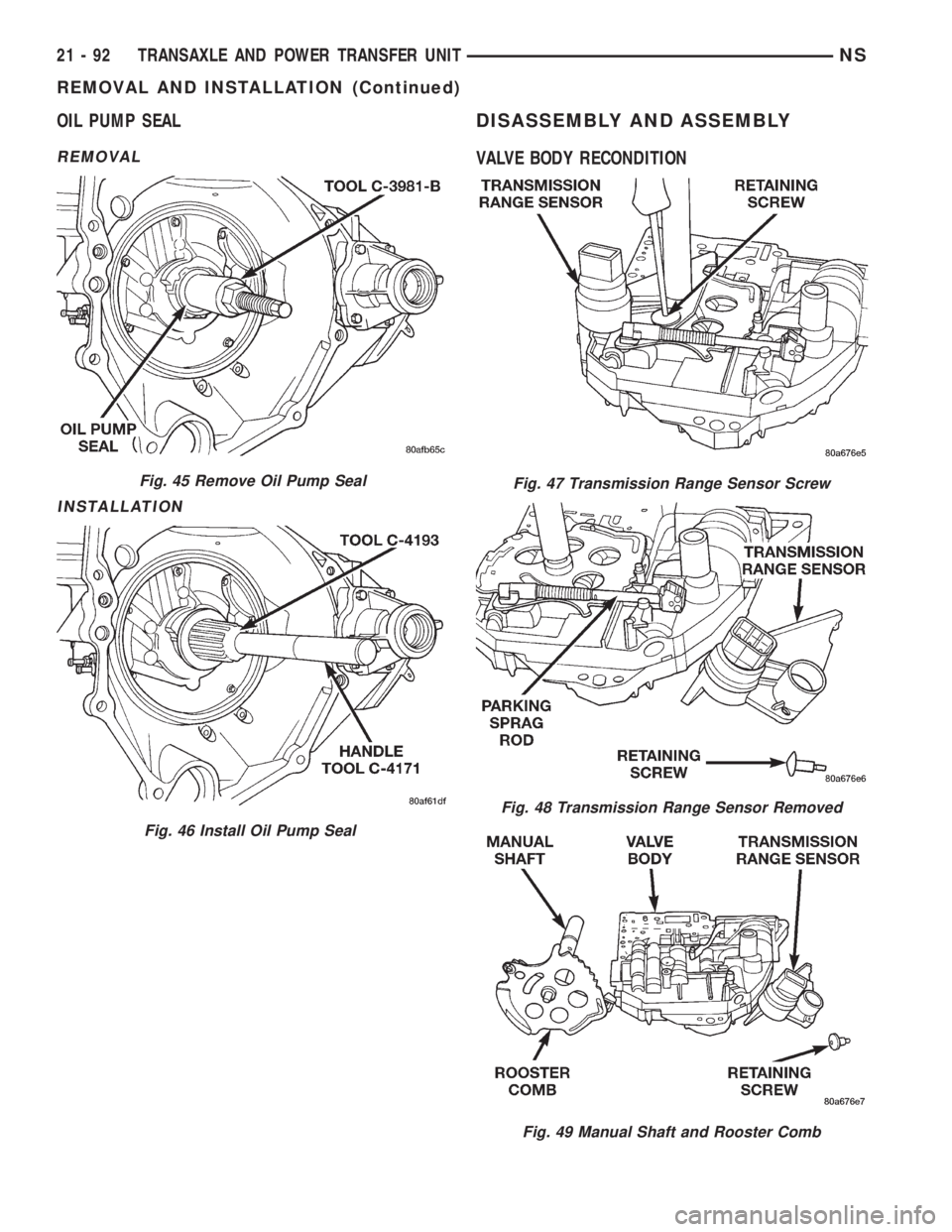
OIL PUMP SEAL
REMOVAL
INSTALLATION
DISASSEMBLY AND ASSEMBLY
VALVE BODY RECONDITION
Fig. 45 Remove Oil Pump Seal
Fig. 46 Install Oil Pump Seal
Fig. 47 Transmission Range Sensor Screw
Fig. 48 Transmission Range Sensor Removed
Fig. 49 Manual Shaft and Rooster Comb
21 - 92 TRANSAXLE AND POWER TRANSFER UNITNS
REMOVAL AND INSTALLATION (Continued)
Page 1567 of 1938
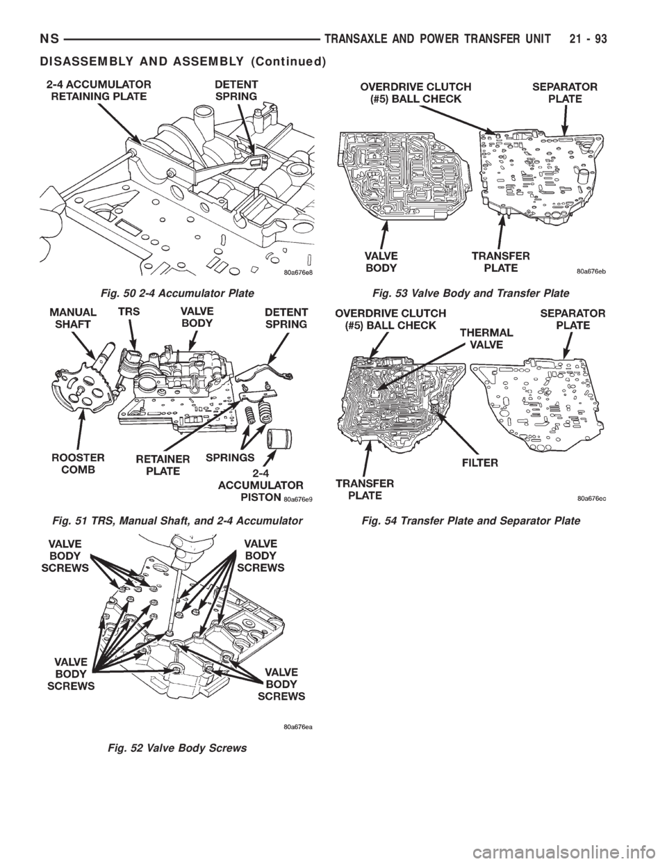
Fig. 50 2-4 Accumulator Plate
Fig. 51 TRS, Manual Shaft, and 2-4 Accumulator
Fig. 52 Valve Body Screws
Fig. 53 Valve Body and Transfer Plate
Fig. 54 Transfer Plate and Separator Plate
NSTRANSAXLE AND POWER TRANSFER UNIT 21 - 93
DISASSEMBLY AND ASSEMBLY (Continued)
Page 1568 of 1938
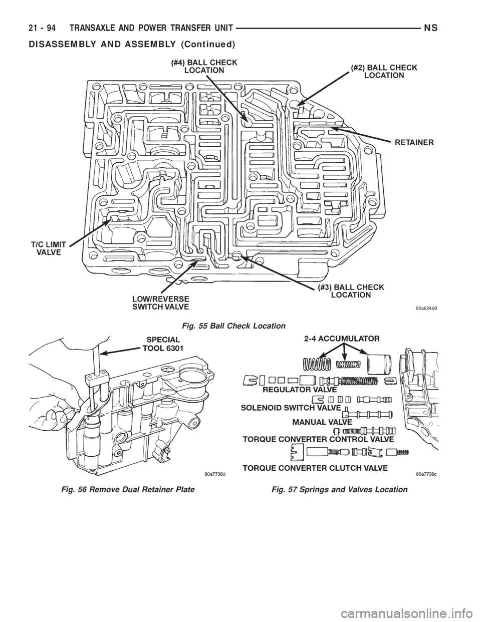
Fig. 55 Ball Check Location
Fig. 56 Remove Dual Retainer PlateFig. 57 Springs and Valves Location
21 - 94 TRANSAXLE AND POWER TRANSFER UNITNS
DISASSEMBLY AND ASSEMBLY (Continued)
Page 1569 of 1938

TRANSAXLE DISASSEMBLE
NOTE: Tag all clutch pack assemblies, as they are
removed, for reassembly identification.
CAUTION: Do not intermix clutch discs or plates as
the unit might then fail.
(1) Remove input and output speed sensors.
(2) Remove transaxle solenoid pack (Fig. 59).
Fig. 58 Low/Reverse Switch Valve And T/C Limit
Valve
Fig. 59 Remove Solenoid Pack
Fig. 60 Remove Oil Pan Bolts
Fig. 61 Remove Oil Pan
Fig. 62 Remove Oil Filter
NSTRANSAXLE AND POWER TRANSFER UNIT 21 - 95
DISASSEMBLY AND ASSEMBLY (Continued)
Page 1570 of 1938
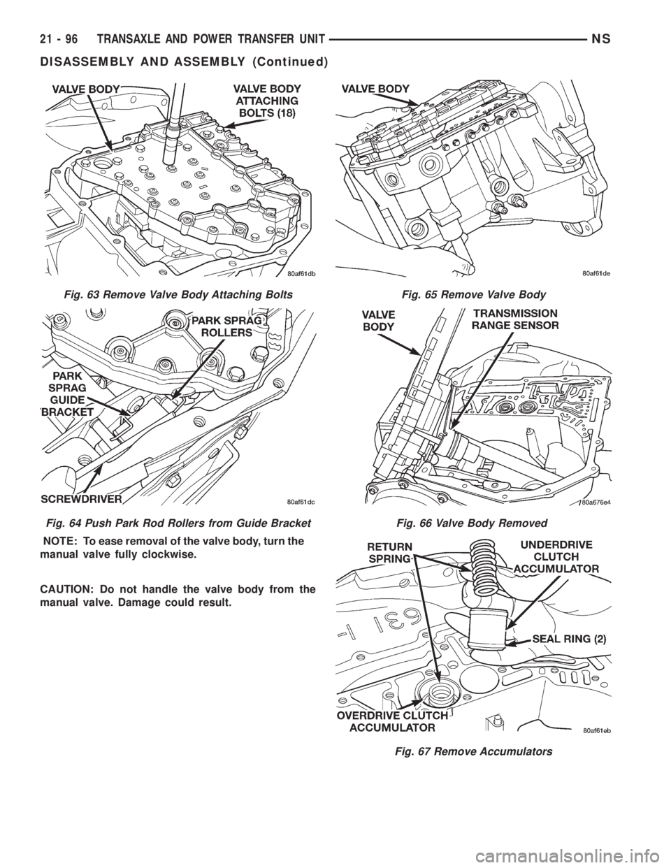
NOTE: To ease removal of the valve body, turn the
manual valve fully clockwise.
CAUTION: Do not handle the valve body from the
manual valve. Damage could result.
Fig. 63 Remove Valve Body Attaching Bolts
Fig. 64 Push Park Rod Rollers from Guide Bracket
Fig. 65 Remove Valve Body
Fig. 66 Valve Body Removed
Fig. 67 Remove Accumulators
21 - 96 TRANSAXLE AND POWER TRANSFER UNITNS
DISASSEMBLY AND ASSEMBLY (Continued)