CHRYSLER VOYAGER 1996 Service Manual
VOYAGER 1996
CHRYSLER
CHRYSLER
https://www.carmanualsonline.info/img/25/56867/w960_56867-0.png
CHRYSLER VOYAGER 1996 Service Manual
Trending: run flat, CD player, wiper blades, oil level, belt, four wheel drive, jump cable
Page 1581 of 1938
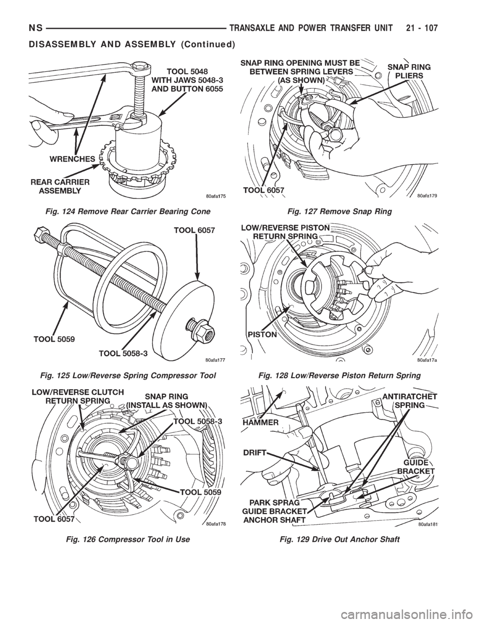
Fig. 124 Remove Rear Carrier Bearing Cone
Fig. 125 Low/Reverse Spring Compressor Tool
Fig. 126 Compressor Tool in Use
Fig. 127 Remove Snap Ring
Fig. 128 Low/Reverse Piston Return Spring
Fig. 129 Drive Out Anchor Shaft
NSTRANSAXLE AND POWER TRANSFER UNIT 21 - 107
DISASSEMBLY AND ASSEMBLY (Continued)
Page 1582 of 1938
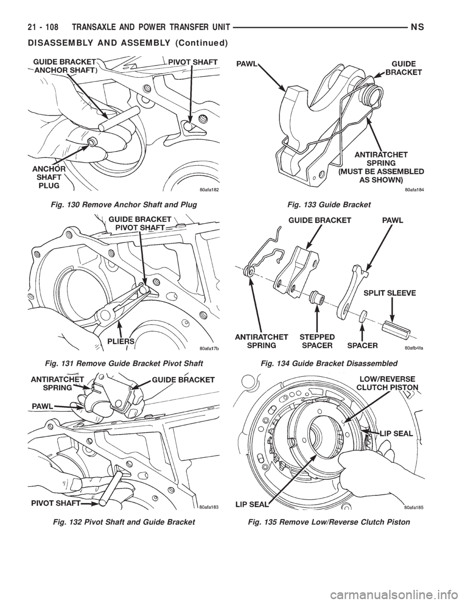
Fig. 130 Remove Anchor Shaft and Plug
Fig. 131 Remove Guide Bracket Pivot Shaft
Fig. 132 Pivot Shaft and Guide Bracket
Fig. 133 Guide Bracket
Fig. 134 Guide Bracket Disassembled
Fig. 135 Remove Low/Reverse Clutch Piston
21 - 108 TRANSAXLE AND POWER TRANSFER UNITNS
DISASSEMBLY AND ASSEMBLY (Continued)
Page 1583 of 1938
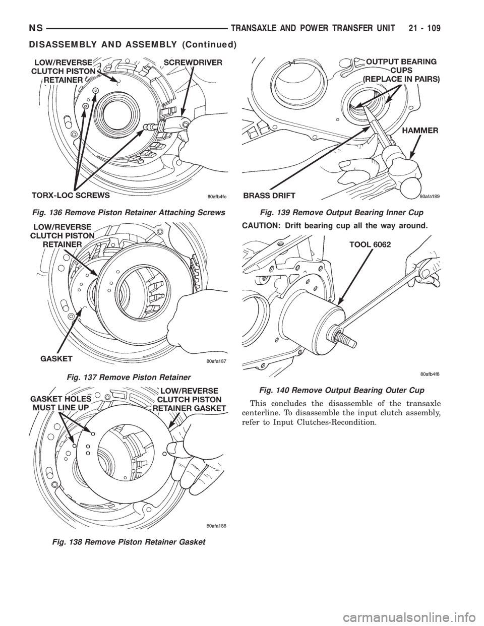
CAUTION: Drift bearing cup all the way around.
This concludes the disassemble of the transaxle
centerline. To disassemble the input clutch assembly,
refer to Input Clutches-Recondition.
Fig. 136 Remove Piston Retainer Attaching Screws
Fig. 137 Remove Piston Retainer
Fig. 138 Remove Piston Retainer Gasket
Fig. 139 Remove Output Bearing Inner Cup
Fig. 140 Remove Output Bearing Outer Cup
NSTRANSAXLE AND POWER TRANSFER UNIT 21 - 109
DISASSEMBLY AND ASSEMBLY (Continued)
Page 1584 of 1938
INPUT CLUTCHES-RECONDITION
DISASSEMBLY
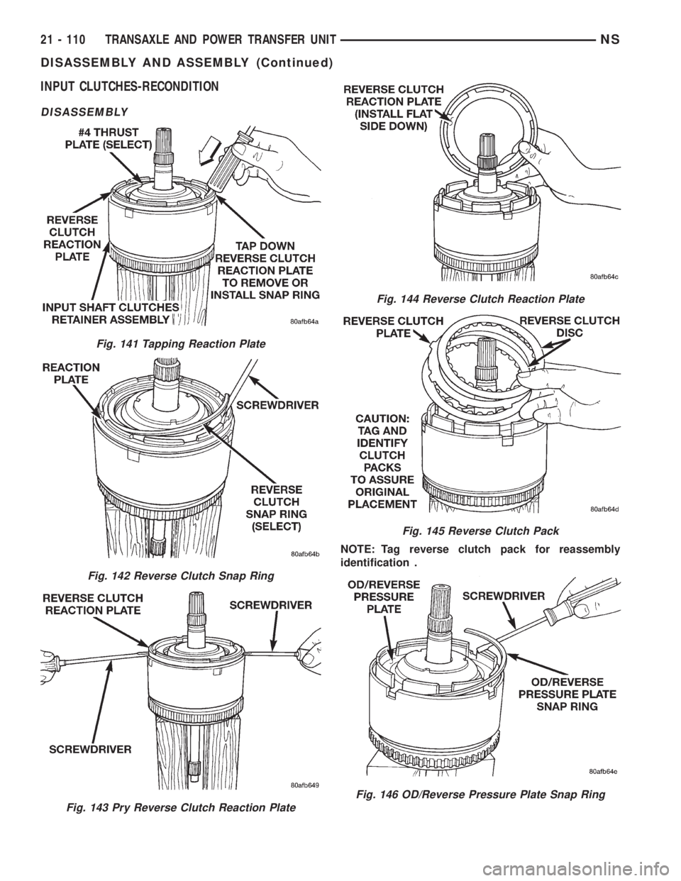
NOTE: Tag reverse clutch pack for reassembly
identification .
Fig. 141 Tapping Reaction Plate
Fig. 142 Reverse Clutch Snap Ring
Fig. 143 Pry Reverse Clutch Reaction Plate
Fig. 144 Reverse Clutch Reaction Plate
Fig. 145 Reverse Clutch Pack
Fig. 146 OD/Reverse Pressure Plate Snap Ring
21 - 110 TRANSAXLE AND POWER TRANSFER UNITNS
DISASSEMBLY AND ASSEMBLY (Continued)
Page 1585 of 1938
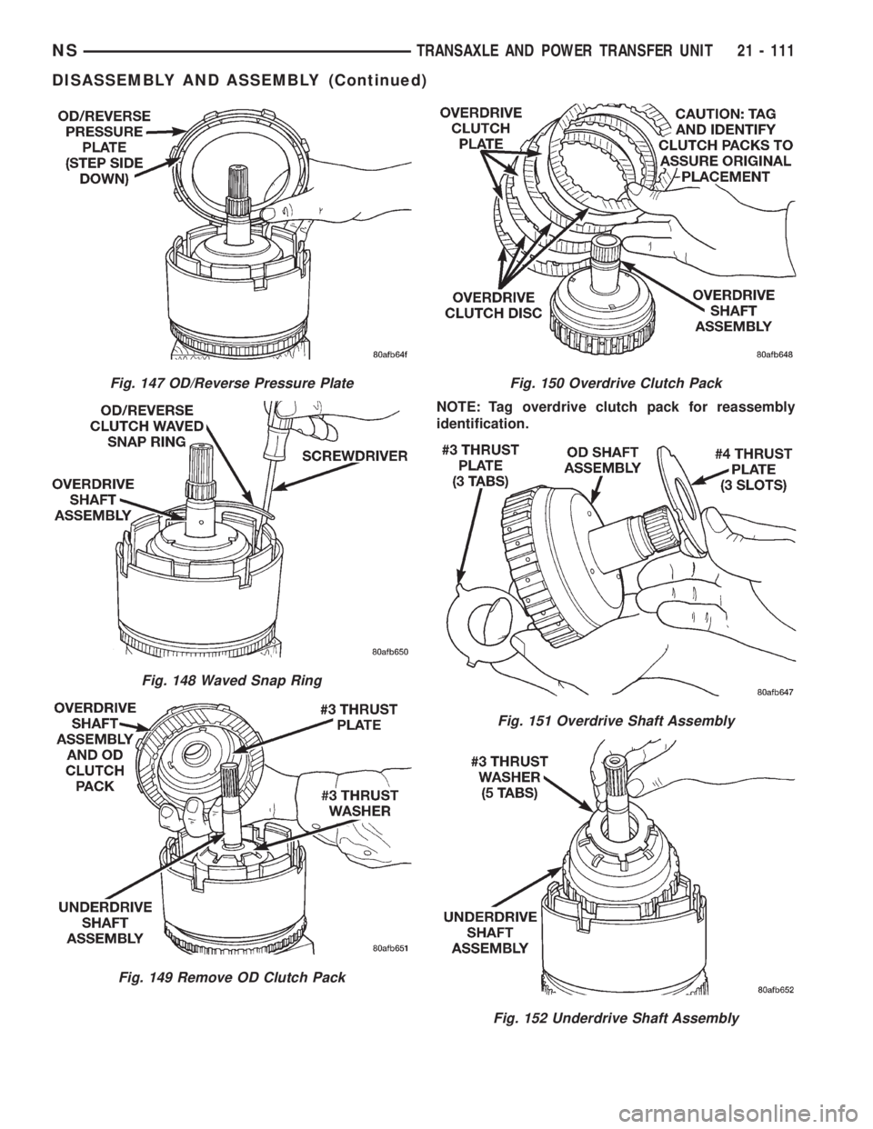
NOTE: Tag overdrive clutch pack for reassembly
identification.
Fig. 147 OD/Reverse Pressure Plate
Fig. 148 Waved Snap Ring
Fig. 149 Remove OD Clutch Pack
Fig. 150 Overdrive Clutch Pack
Fig. 151 Overdrive Shaft Assembly
Fig. 152 Underdrive Shaft Assembly
NSTRANSAXLE AND POWER TRANSFER UNIT 21 - 111
DISASSEMBLY AND ASSEMBLY (Continued)
Page 1586 of 1938
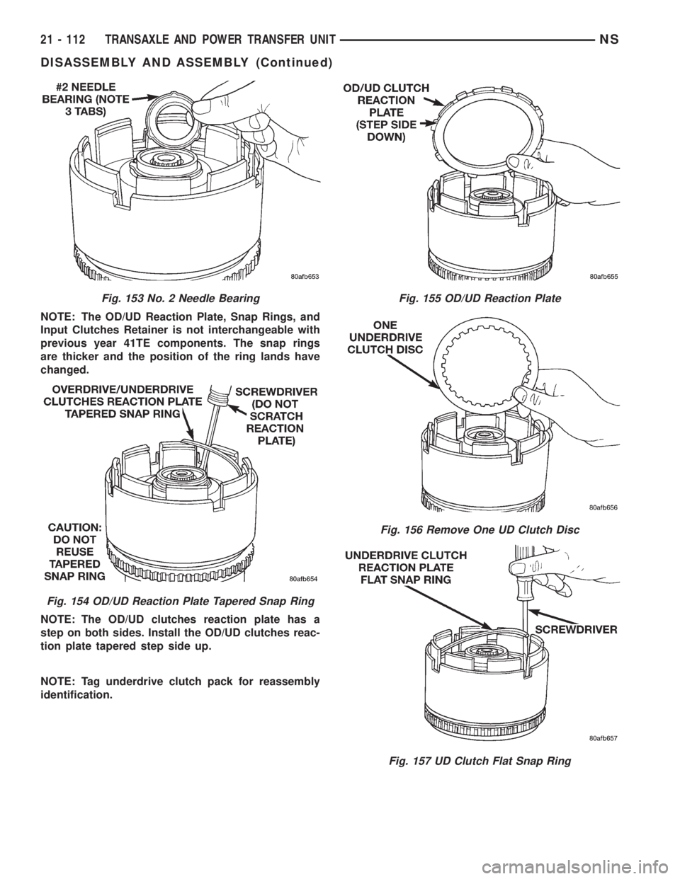
NOTE: The OD/UD Reaction Plate, Snap Rings, and
Input Clutches Retainer is not interchangeable with
previous year 41TE components. The snap rings
are thicker and the position of the ring lands have
changed.
NOTE: The OD/UD clutches reaction plate has a
step on both sides. Install the OD/UD clutches reac-
tion plate tapered step side up.
NOTE: Tag underdrive clutch pack for reassembly
identification.
Fig. 153 No. 2 Needle Bearing
Fig. 154 OD/UD Reaction Plate Tapered Snap Ring
Fig. 155 OD/UD Reaction Plate
Fig. 156 Remove One UD Clutch Disc
Fig. 157 UD Clutch Flat Snap Ring
21 - 112 TRANSAXLE AND POWER TRANSFER UNITNS
DISASSEMBLY AND ASSEMBLY (Continued)
Page 1587 of 1938
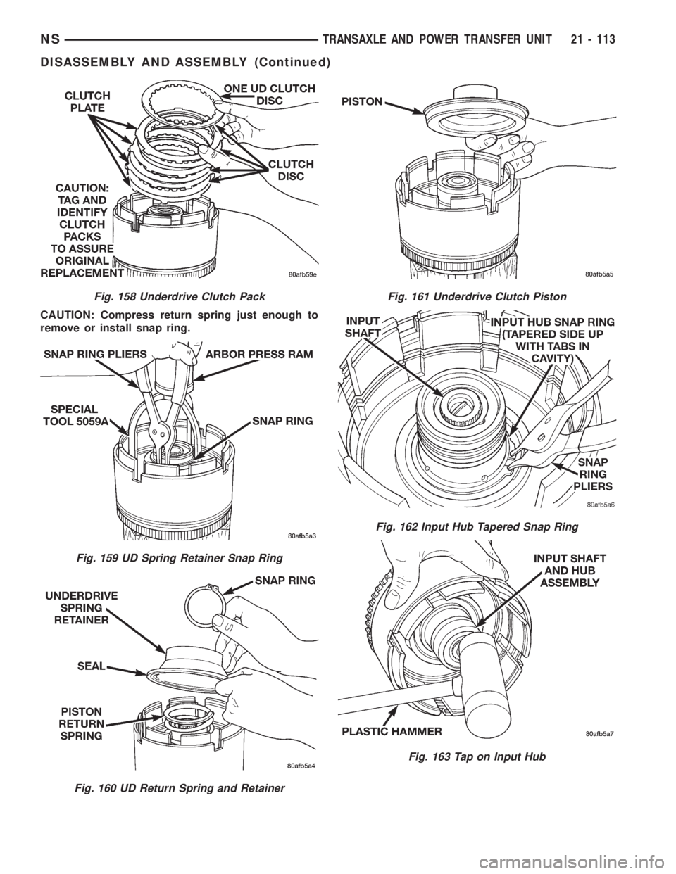
CAUTION: Compress return spring just enough to
remove or install snap ring.
Fig. 158 Underdrive Clutch Pack
Fig. 159 UD Spring Retainer Snap Ring
Fig. 160 UD Return Spring and Retainer
Fig. 161 Underdrive Clutch Piston
Fig. 162 Input Hub Tapered Snap Ring
Fig. 163 Tap on Input Hub
NSTRANSAXLE AND POWER TRANSFER UNIT 21 - 113
DISASSEMBLY AND ASSEMBLY (Continued)
Page 1588 of 1938
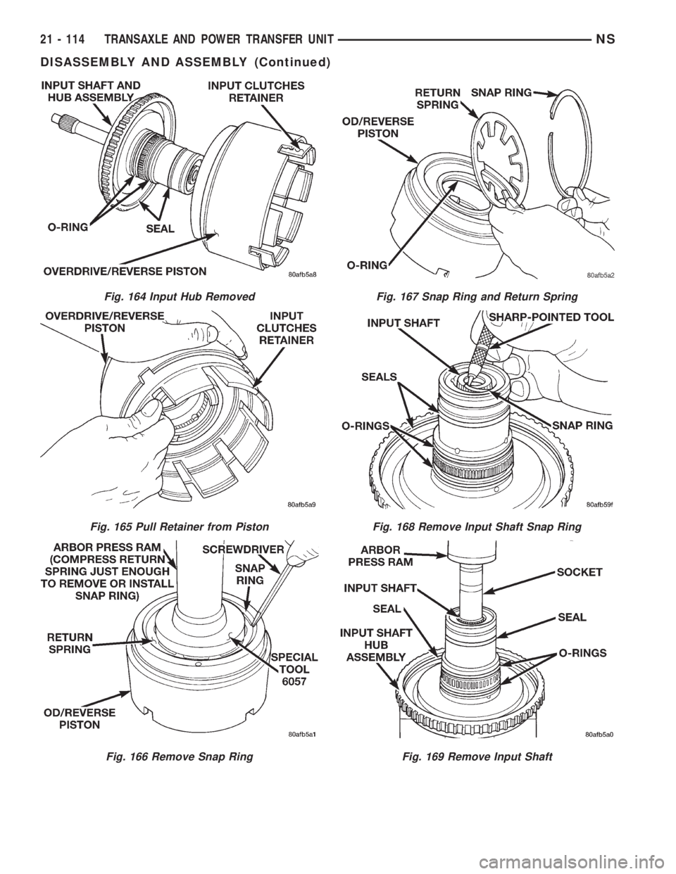
Fig. 164 Input Hub Removed
Fig. 165 Pull Retainer from Piston
Fig. 166 Remove Snap Ring
Fig. 167 Snap Ring and Return Spring
Fig. 168 Remove Input Shaft Snap Ring
Fig. 169 Remove Input Shaft
21 - 114 TRANSAXLE AND POWER TRANSFER UNITNS
DISASSEMBLY AND ASSEMBLY (Continued)
Page 1589 of 1938
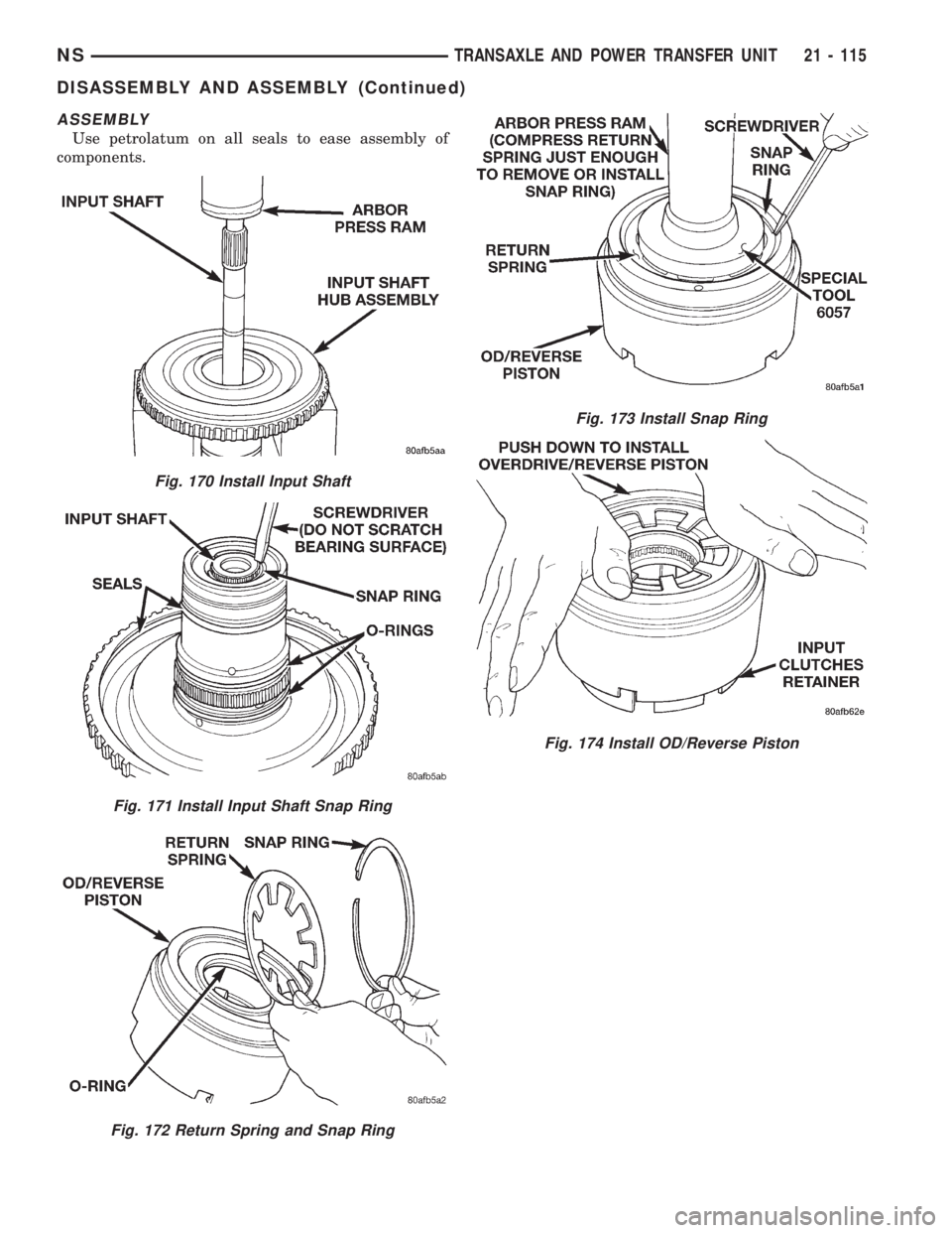
ASSEMBLY
Use petrolatum on all seals to ease assembly of
components.
Fig. 170 Install Input Shaft
Fig. 171 Install Input Shaft Snap Ring
Fig. 172 Return Spring and Snap Ring
Fig. 173 Install Snap Ring
Fig. 174 Install OD/Reverse Piston
NSTRANSAXLE AND POWER TRANSFER UNIT 21 - 115
DISASSEMBLY AND ASSEMBLY (Continued)
Page 1590 of 1938
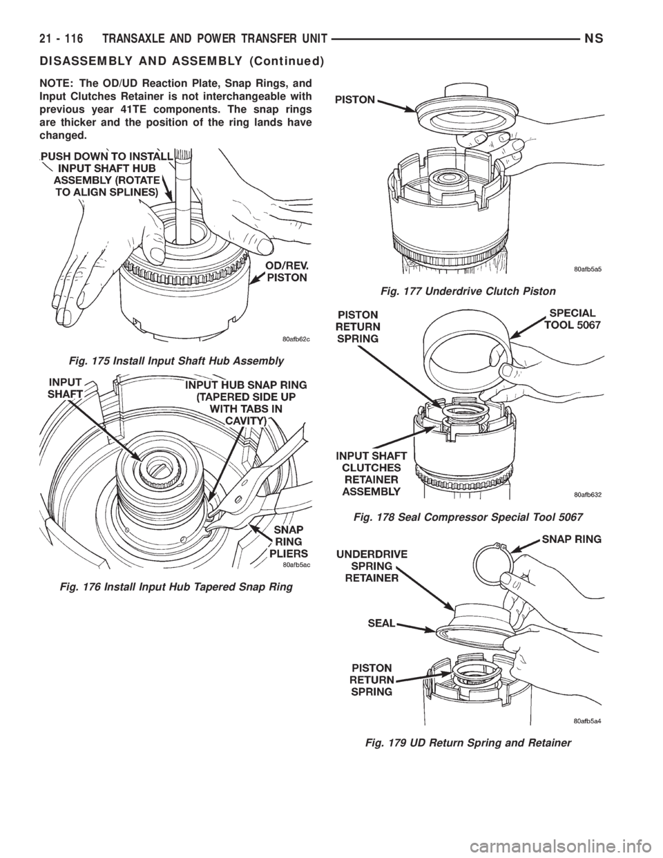
NOTE: The OD/UD Reaction Plate, Snap Rings, and
Input Clutches Retainer is not interchangeable with
previous year 41TE components. The snap rings
are thicker and the position of the ring lands have
changed.
Fig. 175 Install Input Shaft Hub Assembly
Fig. 176 Install Input Hub Tapered Snap Ring
Fig. 177 Underdrive Clutch Piston
Fig. 178 Seal Compressor Special Tool 5067
Fig. 179 UD Return Spring and Retainer
21 - 116 TRANSAXLE AND POWER TRANSFER UNITNS
DISASSEMBLY AND ASSEMBLY (Continued)
Trending: coolant temperature, torque, rear view mirror, oil type, jump start, engine, oil filter
