CHRYSLER VOYAGER 1996 Service Manual
VOYAGER 1996
CHRYSLER
CHRYSLER
https://www.carmanualsonline.info/img/25/56867/w960_56867-0.png
CHRYSLER VOYAGER 1996 Service Manual
Trending: remote start, high beam, mirror, wheel bolts, four wheel drive, ABS, steering
Page 1631 of 1938
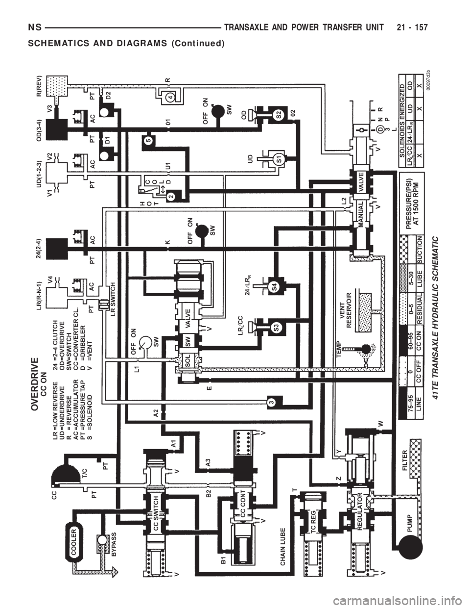
41TE TRANSAXLE HYDRAULIC SCHEMATIC
NSTRANSAXLE AND POWER TRANSFER UNIT 21 - 157
SCHEMATICS AND DIAGRAMS (Continued)
Page 1632 of 1938
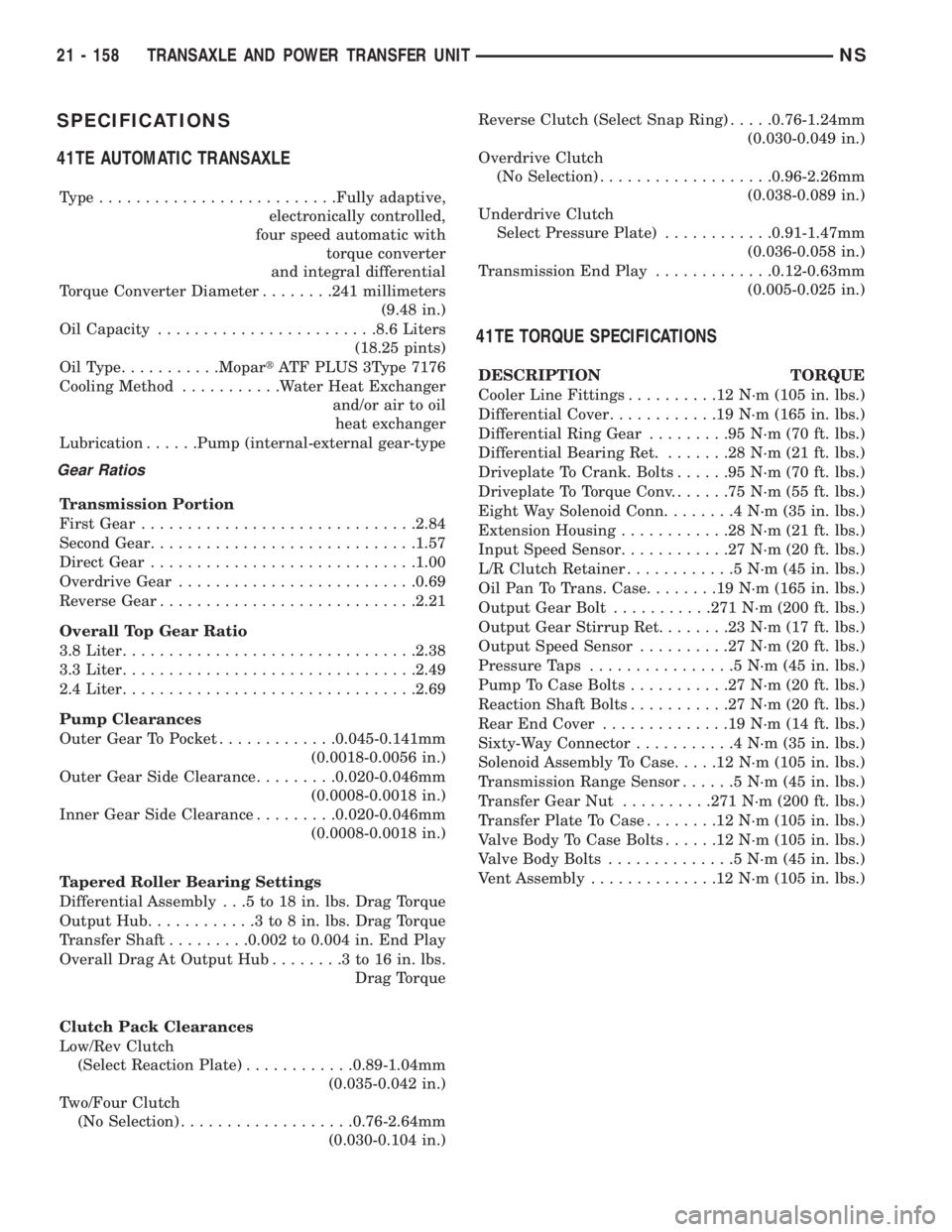
SPECIFICATIONS
41TE AUTOMATIC TRANSAXLE
Type..........................Fully adaptive,
electronically controlled,
four speed automatic with
torque converter
and integral differential
Torque Converter Diameter........241 millimeters
(9.48 in.)
Oil Capacity........................8.6 Liters
(18.25 pints)
OilType...........MopartATF PLUS 3Type 7176
Cooling Method...........Water Heat Exchanger
and/or air to oil
heat exchanger
Lubrication......Pump (internal-external gear-type
Gear Ratios
Transmission Portion
First Gear..............................2.84
Second Gear.............................1.57
Direct Gear.............................1.00
Overdrive Gear..........................0.69
Reverse Gear............................2.21
Overall Top Gear Ratio
3.8 Liter................................2.38
3.3 Liter................................2.49
2.4 Liter................................2.69
Pump Clearances
Outer Gear To Pocket.............0.045-0.141mm
(0.0018-0.0056 in.)
Outer Gear Side Clearance.........0.020-0.046mm
(0.0008-0.0018 in.)
Inner Gear Side Clearance.........0.020-0.046mm
(0.0008-0.0018 in.)
Tapered Roller Bearing Settings
Differential Assembly . . .5 to 18 in. lbs. Drag Torque
Output Hub............3to8in.lbs. Drag Torque
Transfer Shaft.........0.002 to 0.004 in. End Play
Overall Drag At Output Hub........3to16in.lbs.
Drag Torque
Clutch Pack Clearances
Low/Rev Clutch
(Select Reaction Plate)............0.89-1.04mm
(0.035-0.042 in.)
Two/Four Clutch
(No Selection)...................0.76-2.64mm
(0.030-0.104 in.)Reverse Clutch (Select Snap Ring).....0.76-1.24mm
(0.030-0.049 in.)
Overdrive Clutch
(No Selection)...................0.96-2.26mm
(0.038-0.089 in.)
Underdrive Clutch
Select Pressure Plate)............0.91-1.47mm
(0.036-0.058 in.)
Transmission End Play.............0.12-0.63mm
(0.005-0.025 in.)
41TE TORQUE SPECIFICATIONS
DESCRIPTION TORQUE
Cooler Line Fittings..........12N´m(105 in. lbs.)
Differential Cover............19N´m(165 in. lbs.)
Differential Ring Gear.........95N´m(70ft.lbs.)
Differential Bearing Ret........28N´m(21ft.lbs.)
Driveplate To Crank. Bolts......95N´m(70ft.lbs.)
Driveplate To Torque Conv.......75N´m(55ft.lbs.)
Eight Way Solenoid Conn........4N´m(35in.lbs.)
Extension Housing............28N´m(21ft.lbs.)
Input Speed Sensor............27N´m(20ft.lbs.)
L/R Clutch Retainer............5N´m(45in.lbs.)
Oil Pan To Trans. Case........19N´m(165 in. lbs.)
Output Gear Bolt...........271 N´m (200 ft. lbs.)
Output Gear Stirrup Ret........23N´m(17ft.lbs.)
Output Speed Sensor..........27N´m(20ft.lbs.)
Pressure Taps................5N´m(45in.lbs.)
Pump To Case Bolts...........27N´m(20ft.lbs.)
Reaction Shaft Bolts...........27N´m(20ft.lbs.)
Rear End Cover..............19N´m(14ft.lbs.)
Sixty-Way Connector...........4N´m(35in.lbs.)
Solenoid Assembly To Case.....12N´m(105 in. lbs.)
Transmission Range Sensor......5N´m(45in.lbs.)
Transfer Gear Nut..........271 N´m (200 ft. lbs.)
Transfer Plate To Case........12N´m(105 in. lbs.)
Valve Body To Case Bolts......12N´m(105 in. lbs.)
Valve Body Bolts..............5N´m(45in.lbs.)
Vent Assembly..............12N´m(105 in. lbs.)
21 - 158 TRANSAXLE AND POWER TRANSFER UNITNS
Page 1633 of 1938
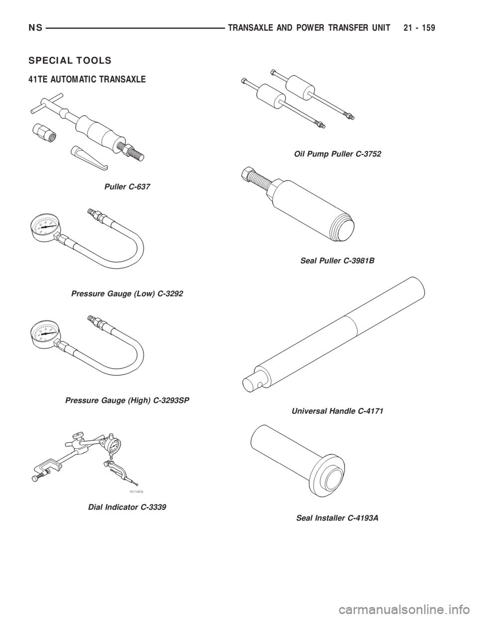
SPECIAL TOOLS
41TE AUTOMATIC TRANSAXLE
Puller C-637
Pressure Gauge (Low) C-3292
Pressure Gauge (High) C-3293SP
Dial Indicator C-3339
Oil Pump Puller C-3752
Seal Puller C-3981B
Universal Handle C-4171
Seal Installer C-4193A
NSTRANSAXLE AND POWER TRANSFER UNIT 21 - 159
Page 1634 of 1938
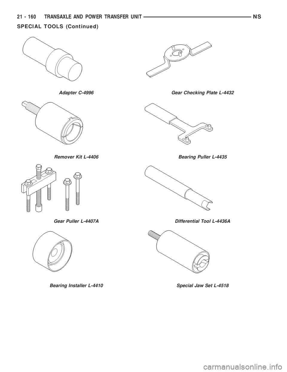
Adapter C-4996
Remover Kit L-4406
Gear Puller L-4407A
Bearing Installer L-4410
Gear Checking Plate L-4432
Bearing Puller L-4435
Differential Tool L-4436A
Special Jaw Set L-4518
21 - 160 TRANSAXLE AND POWER TRANSFER UNITNS
SPECIAL TOOLS (Continued)
Page 1635 of 1938
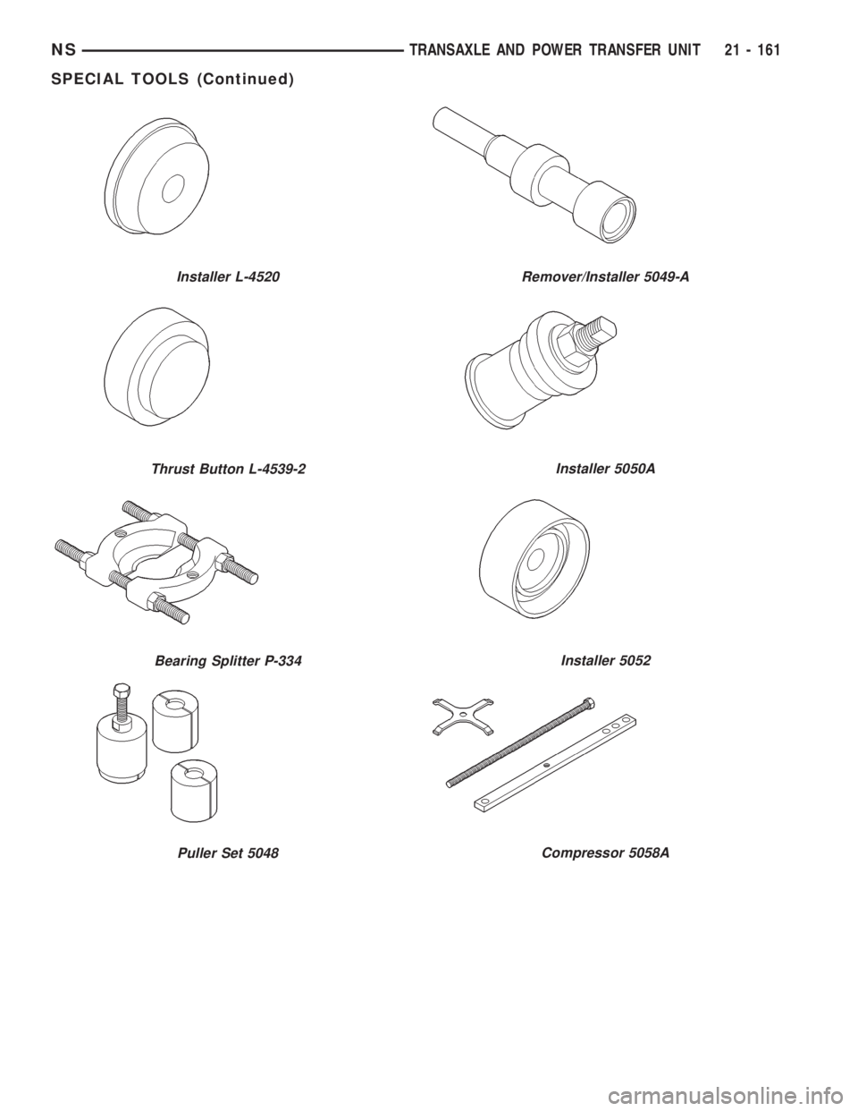
Installer L-4520
Thrust Button L-4539-2
Bearing Splitter P-334
Puller Set 5048
Remover/Installer 5049-A
Installer 5050A
Installer 5052
Compressor 5058A
NSTRANSAXLE AND POWER TRANSFER UNIT 21 - 161
SPECIAL TOOLS (Continued)
Page 1636 of 1938
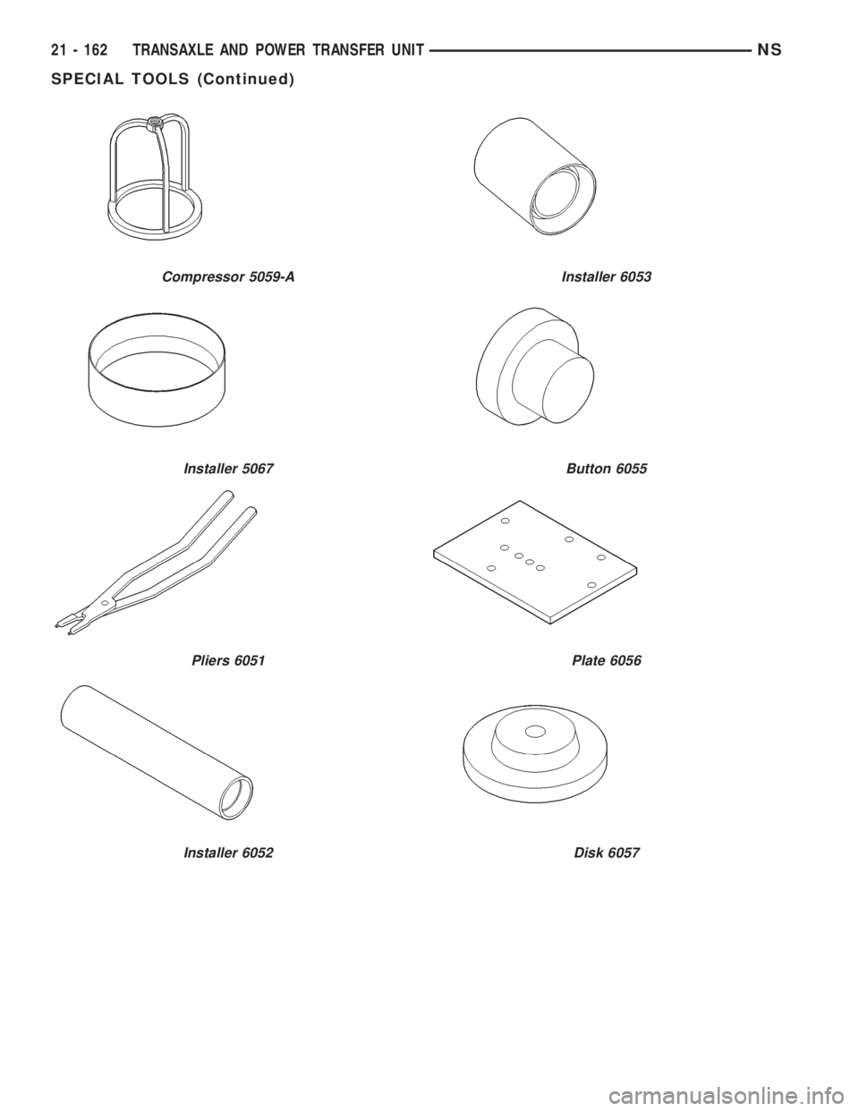
Compressor 5059-A
Installer 5067
Pliers 6051
Installer 6052
Installer 6053
Button 6055
Plate 6056
Disk 6057
21 - 162 TRANSAXLE AND POWER TRANSFER UNITNS
SPECIAL TOOLS (Continued)
Page 1637 of 1938
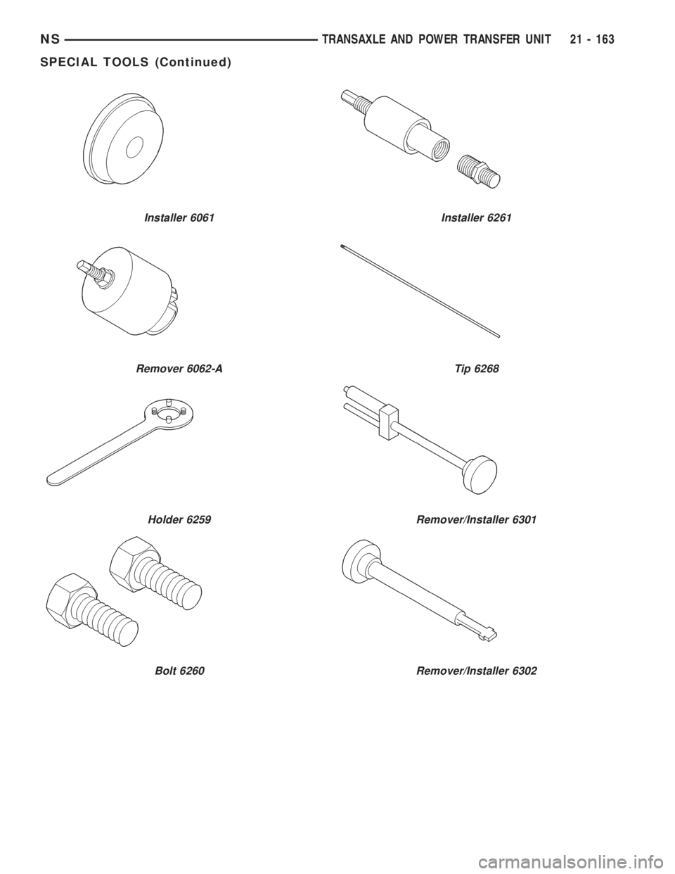
Installer 6061
Remover 6062-A
Holder 6259
Bolt 6260
Installer 6261
Tip 6268
Remover/Installer 6301
Remover/Installer 6302
NSTRANSAXLE AND POWER TRANSFER UNIT 21 - 163
SPECIAL TOOLS (Continued)
Page 1638 of 1938
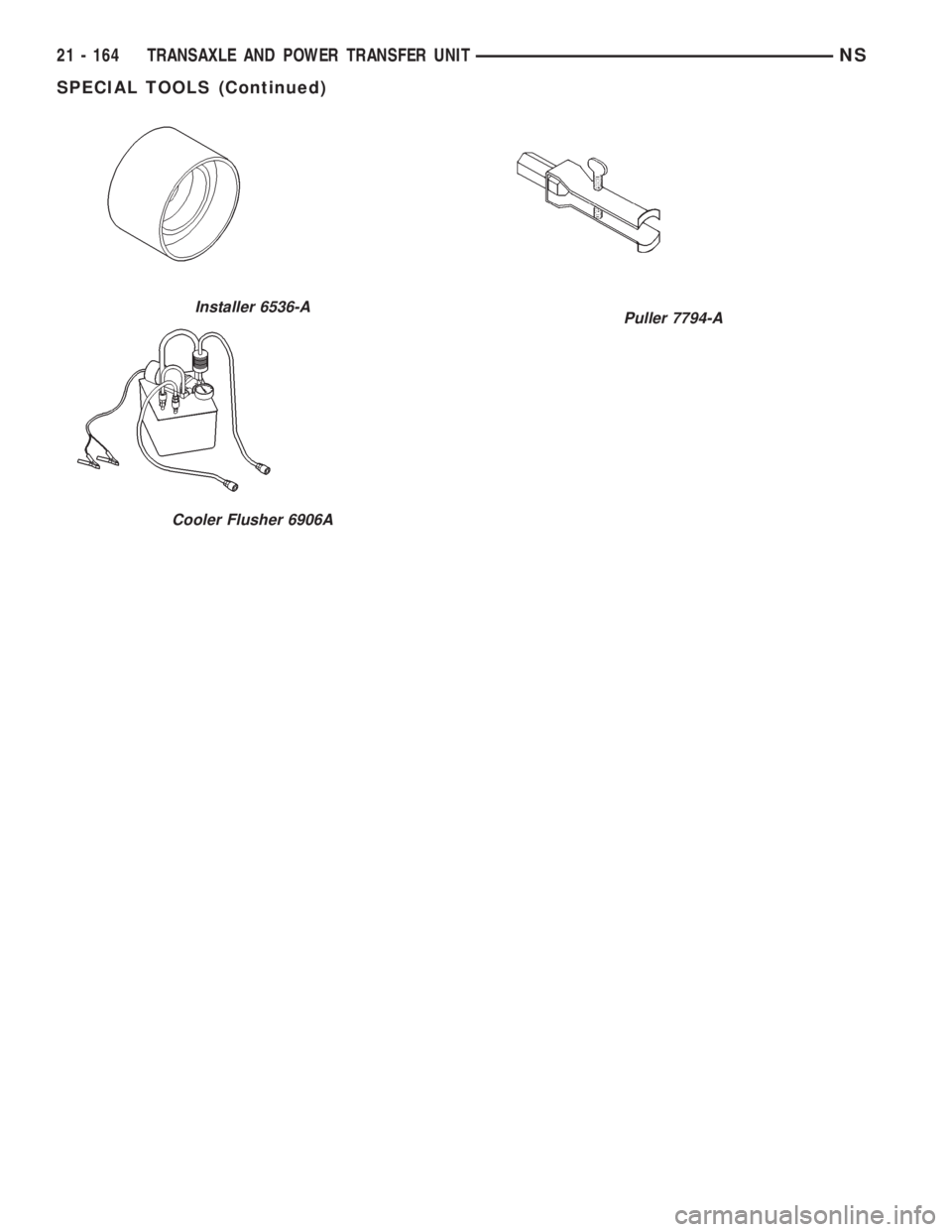
Installer 6536-A
Cooler Flusher 6906A
Puller 7794-A
21 - 164 TRANSAXLE AND POWER TRANSFER UNITNS
SPECIAL TOOLS (Continued)
Page 1639 of 1938
POWER TRANSFER UNIT
INDEX
page page
GENERAL INFORMATION
POWER TRANSFER UNIT................ 165
DIAGNOSIS AND TESTING
FLUID LEAK DIAGNOSIS................. 167
SEAL IDENTIFICATION................... 165
REMOVAL AND INSTALLATION
DIFFERENTIAL CARRIER SEAL............ 170
END COVER BALL BEARING.............. 178
END COVER SEAL...................... 169
HALF SHAFT INNER SEAL................ 175
INPUT SHAFT COVER SEAL.............. 174
INPUT SHAFT END SEAL................. 177INPUT SHAFT SEAL..................... 169
OUTER HALF SHAFT SEAL............... 177
POWER TRANSFER UNIT (P.T.U.).......... 167
POWER TRANSFER UNIT OUTPUT SEAL.... 171
REAR COVER O-RING................... 171
ADJUSTMENTS
OUTPUT FLANGE SHIM SELECTION........ 180
SPECIFICATIONS
TORQUE............................. 180
SPECIAL TOOLS
SDP POWER TRANSFER UNIT............ 181
GENERAL INFORMATION
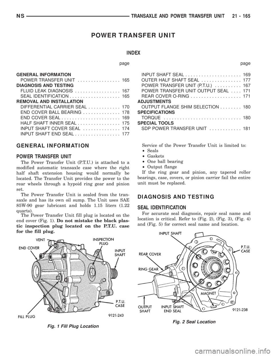
POWER TRANSFER UNIT
The Power Transfer Unit (P.T.U.) is attached to a
modified automatic transaxle case where the right
half shaft extension housing would normally be
located. The Transfer Unit provides the power to the
rear wheels through a hypoid ring gear and pinion
set.
The Power Transfer Unit is sealed from the tran-
saxle and has its own oil sump. The Unit uses SAE
85W-90 gear lubricant and holds 1.15 liters (1.22
quarts).
The Power Transfer Unit fill plug is located on the
end cover (Fig. 1).Do not mistake the black plas-
tic inspection plug located on the P.T.U. case
for the fill plug.Service of the Power Transfer Unit is limited to:
²Seals
²Gaskets
²One ball bearing
²Output flange
If the ring gear and pinion, any tapered roller
bearings, case, covers, or pinion carrier fail the entire
unit must be replaced.
DIAGNOSIS AND TESTING
SEAL IDENTIFICATION
For accurate seal diagnosis, repair seal name and
location is critical. Refer to (Fig. 2), (Fig. 3), (Fig. 4)
and (Fig. 5) for correct seal name and location.
Fig. 1 Fill Plug LocationFig. 2 Seal Location
NSTRANSAXLE AND POWER TRANSFER UNIT 21 - 165
Page 1640 of 1938
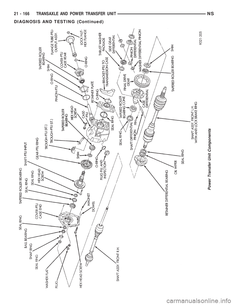
Power Transfer Unit Components
21 - 166 TRANSAXLE AND POWER TRANSFER UNITNS
DIAGNOSIS AND TESTING (Continued)
Trending: shaft, key fob, engine coolant, wheel torque, fuel, spark plugs replace, servo
