CHRYSLER VOYAGER 1996 Service Manual
VOYAGER 1996
CHRYSLER
CHRYSLER
https://www.carmanualsonline.info/img/25/56867/w960_56867-0.png
CHRYSLER VOYAGER 1996 Service Manual
Trending: wheel, hood open, brake rotor, clock, boot, suspension, radio antenna
Page 1691 of 1938
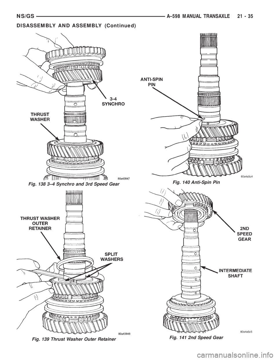
Fig. 139 Thrust Washer Outer Retainer
Fig. 138 3±4 Synchro and 3rd Speed GearFig. 140 Anti-Spin Pin
Fig. 141 2nd Speed Gear
NS/GSA±598 MANUAL TRANSAXLE 21 - 35
DISASSEMBLY AND ASSEMBLY (Continued)
Page 1692 of 1938
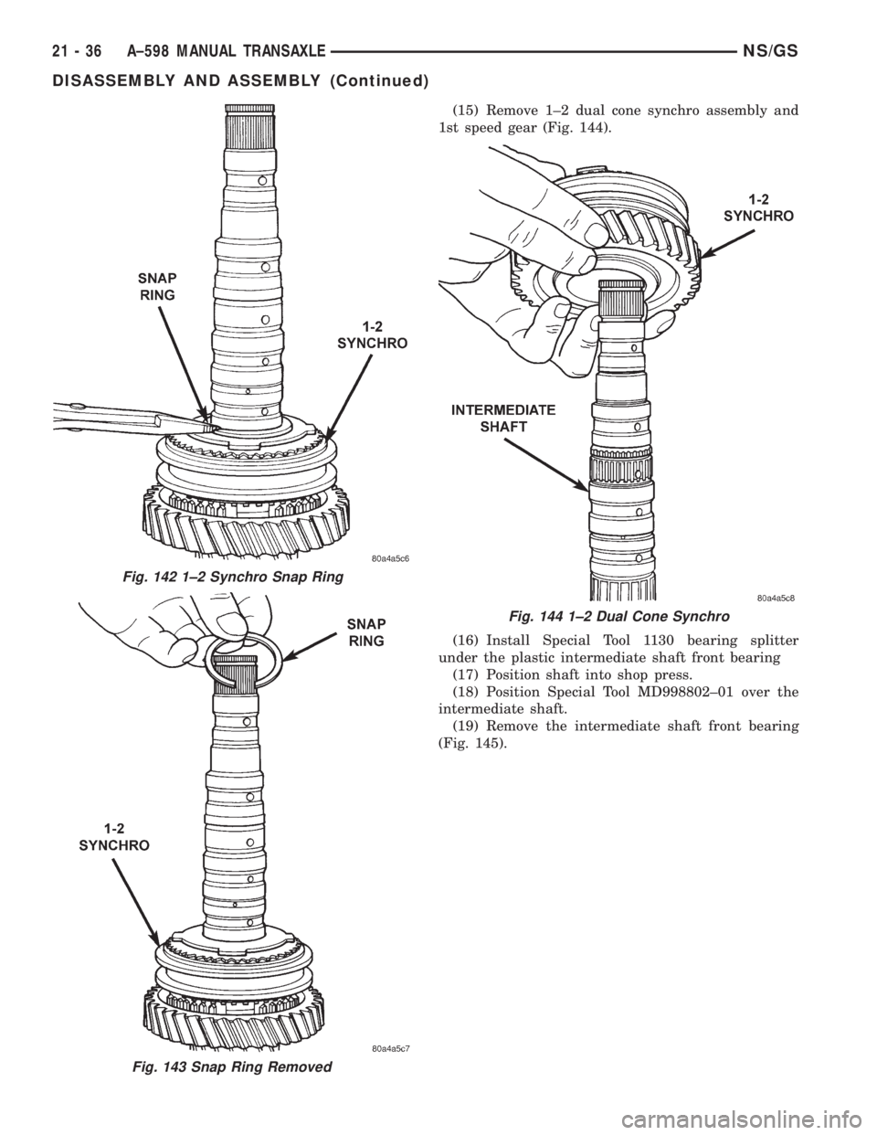
(15) Remove 1±2 dual cone synchro assembly and
1st speed gear (Fig. 144).
(16) Install Special Tool 1130 bearing splitter
under the plastic intermediate shaft front bearing
(17) Position shaft into shop press.
(18) Position Special Tool MD998802±01 over the
intermediate shaft.
(19) Remove the intermediate shaft front bearing
(Fig. 145).
Fig. 143 Snap Ring Removed
Fig. 142 1±2 Synchro Snap Ring
Fig. 144 1±2 Dual Cone Synchro
21 - 36 A±598 MANUAL TRANSAXLENS/GS
DISASSEMBLY AND ASSEMBLY (Continued)
Page 1693 of 1938
ASSEMBLY
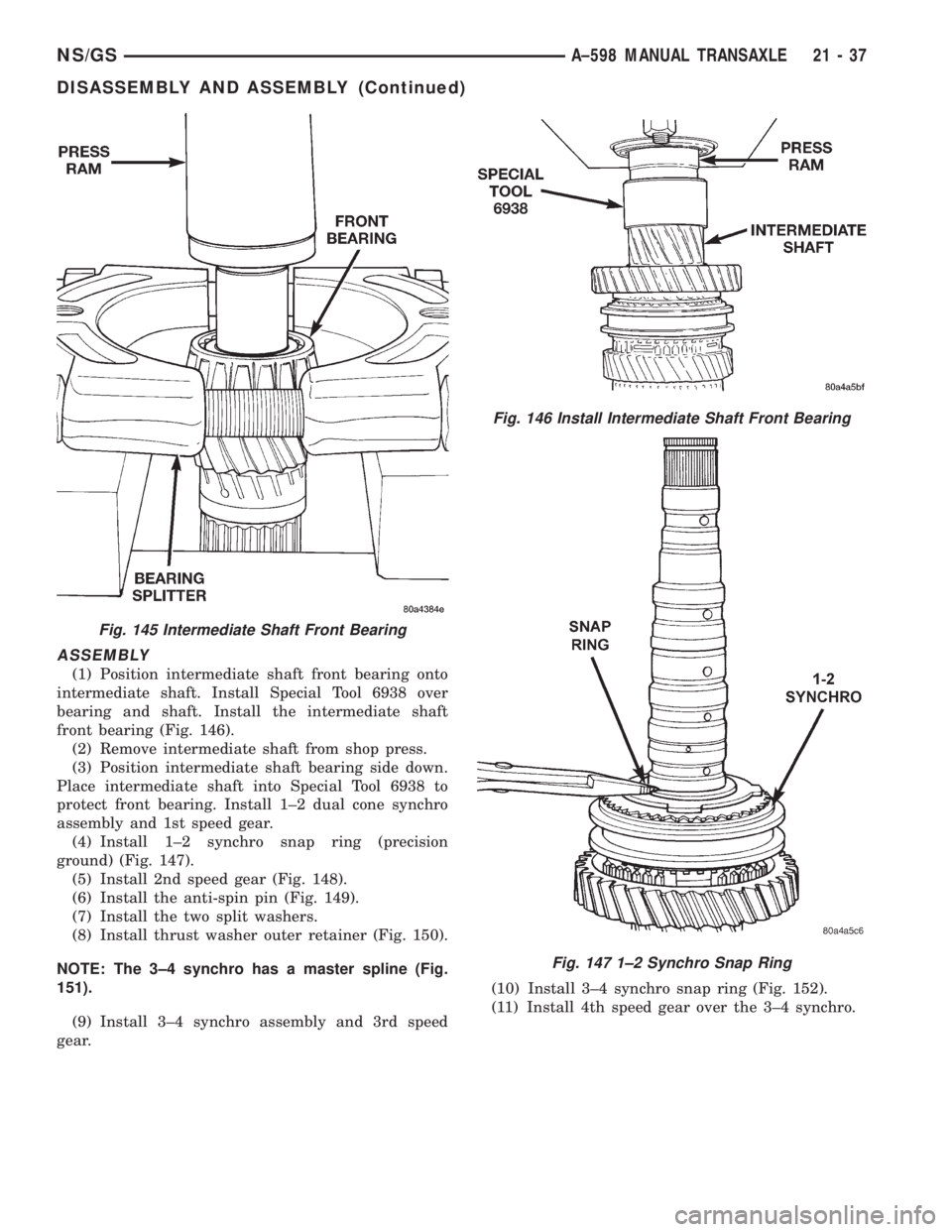
(1) Position intermediate shaft front bearing onto
intermediate shaft. Install Special Tool 6938 over
bearing and shaft. Install the intermediate shaft
front bearing (Fig. 146).
(2) Remove intermediate shaft from shop press.
(3) Position intermediate shaft bearing side down.
Place intermediate shaft into Special Tool 6938 to
protect front bearing. Install 1±2 dual cone synchro
assembly and 1st speed gear.
(4) Install 1±2 synchro snap ring (precision
ground) (Fig. 147).
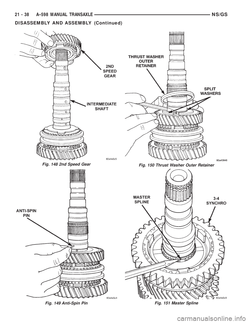
(5) Install 2nd speed gear (Fig. 148).
(6) Install the anti-spin pin (Fig. 149).
(7) Install the two split washers.
(8) Install thrust washer outer retainer (Fig. 150).
NOTE: The 3±4 synchro has a master spline (Fig.
151).
(9) Install 3±4 synchro assembly and 3rd speed
gear.(10) Install 3±4 synchro snap ring (Fig. 152).
(11) Install 4th speed gear over the 3±4 synchro.
Fig. 145 Intermediate Shaft Front Bearing
Fig. 146 Install Intermediate Shaft Front Bearing
Fig. 147 1±2 Synchro Snap Ring
NS/GSA±598 MANUAL TRANSAXLE 21 - 37
DISASSEMBLY AND ASSEMBLY (Continued)
Page 1694 of 1938
Fig. 148 2nd Speed Gear
Fig. 151 Master SplineFig. 149 Anti-Spin Pin
Fig. 150 Thrust Washer Outer Retainer
21 - 38 A±598 MANUAL TRANSAXLENS/GS
DISASSEMBLY AND ASSEMBLY (Continued)
Page 1695 of 1938
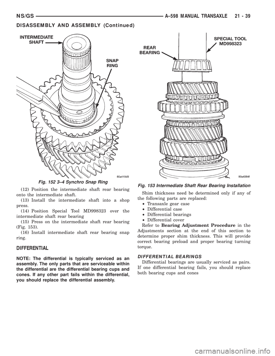
(12) Position the intermediate shaft rear bearing
onto the intermediate shaft.
(13) Install the intermediate shaft into a shop
press.
(14) Position Special Tool MD998323 over the
intermediate shaft rear bearing
(15) Press on the intermediate shaft rear bearing
(Fig. 153).
(16) Install intermediate shaft rear bearing snap
ring.
DIFFERENTIAL
NOTE: The differential is typically serviced as an
assembly. The only parts that are serviceable within
the differential are the differential bearing cups and
cones. If any other part fails within the differential,
you should replace the differential assembly.Shim thickness need be determined only if any of
the following parts are replaced:
²Transaxle gear case
²Differential case
²Differential bearings
²Differential cover
Refer toBearing Adjustment Procedurein the
Adjustments section at the end of this section to
determine proper shim thickness. This will provide
correct bearing preload and proper bearing turning
torque.DIFFERENTIAL BEARINGS
Differential bearings are usually serviced as pairs.
If one differential bearing fails, you should replace
both bearing cups and cones
Fig. 152 3±4 Synchro Snap RingFig. 153 Intermediate Shaft Rear Bearing Installation
NS/GSA±598 MANUAL TRANSAXLE 21 - 39
DISASSEMBLY AND ASSEMBLY (Continued)
Page 1696 of 1938
.
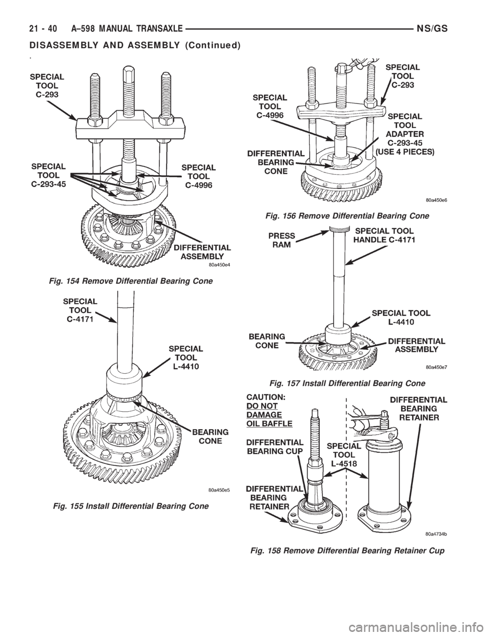
Fig. 154 Remove Differential Bearing Cone
Fig. 155 Install Differential Bearing Cone
Fig. 156 Remove Differential Bearing Cone
Fig. 157 Install Differential Bearing Cone
Fig. 158 Remove Differential Bearing Retainer Cup
21 - 40 A±598 MANUAL TRANSAXLENS/GS
DISASSEMBLY AND ASSEMBLY (Continued)
Page 1697 of 1938
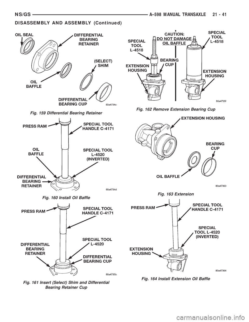
Fig. 159 Differential Bearing Retainer
Fig. 160 Install Oil Baffle
Fig. 161 Insert (Select) Shim and Differential
Bearing Retainer Cup
Fig. 162 Remove Extension Bearing Cup
Fig. 163 Extension
Fig. 164 Install Extension Oil Baffle
NS/GSA±598 MANUAL TRANSAXLE 21 - 41
DISASSEMBLY AND ASSEMBLY (Continued)
Page 1698 of 1938
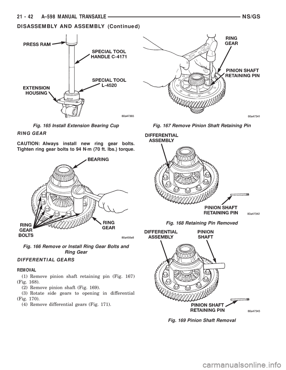
RING GEAR
CAUTION: Always install new ring gear bolts.
Tighten ring gear bolts to 94 N´m (70 ft. lbs.) torque.
DIFFERENTIAL GEARS
REMOVAL
(1) Remove pinion shaft retaining pin (Fig. 167)
(Fig. 168).
(2) Remove pinion shaft (Fig. 169).
(3) Rotate side gears to opening in differential
(Fig. 170).
(4) Remove differential gears (Fig. 171).
Fig. 165 Install Extension Bearing Cup
Fig. 166 Remove or Install Ring Gear Bolts and
Ring Gear
Fig. 167 Remove Pinion Shaft Retaining Pin
Fig. 168 Retaining Pin Removed
Fig. 169 Pinion Shaft Removal
21 - 42 A±598 MANUAL TRANSAXLENS/GS
DISASSEMBLY AND ASSEMBLY (Continued)
Page 1699 of 1938
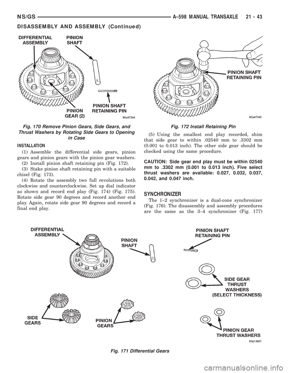
INSTALLATION
(1) Assemble the differential side gears, pinion
gears and pinion gears with the pinion gear washers.
(2) Install pinion shaft retaining pin (Fig. 172).
(3) Stake pinion shaft retaining pin with a suitable
chisel (Fig. 173).
(4) Rotate the assembly two full revolutions both
clockwise and counterclockwise. Set up dial indicator
as shown and record end play (Fig. 174) (Fig. 175).
Rotate side gear 90 degrees and record another end
play. Again, rotate side gear 90 degrees and record a
final end play.(5) Using the smallest end play recorded, shim
that side gear to within .02540 mm to .3302 mm
(0.001 to 0.013 inch). The other side gear should be
checked using the same procedure.
CAUTION: Side gear end play must be within 02540
mm to .3302 mm (0.001 to 0.013 inch). Five select
thrust washers are available: 0.027, 0.032, 0.037,
0.042, and 0.047 inch.
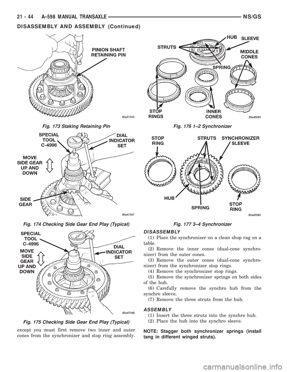
SYNCHRONIZER
The 1±2 synchronizer is a dual-cone synchronizer
(Fig. 176). The disassembly and assembly procedures
are the same as the 3±4 synchronizer (Fig. 177)
Fig. 171 Differential Gears
Fig. 170 Remove Pinion Gears, Side Gears, and
Thrust Washers by Rotating Side Gears to Opening
in CaseFig. 172 Install Retaining Pin
NS/GSA±598 MANUAL TRANSAXLE 21 - 43
DISASSEMBLY AND ASSEMBLY (Continued)
Page 1700 of 1938
except you must first remove two inner and outer
cones from the synchronizer and stop ring assembly.
DISASSEMBLY
(1) Place the synchronizer on a clean shop rag on a
table.
(2) Remove the inner cones (dual-cone synchro-
nizer) from the outer cones.
(3) Remove the outer cones (dual-cone synchro-
nizer) from the synchronizer stop rings.
(4) Remove the synchronizer stop rings.
(5) Remove the synchronizer springs on both sides
of the hub.
(6) Carefully remove the synchro hub from the
synchro sleeve.
(7) Remove the three struts from the hub.
ASSEMBLY
(1) Insert the three struts into the synchro hub.
(2) Place the hub into the synchro sleeve.
NOTE: Stagger both synchronizer springs (install
tang in different winged struts).
Fig. 173 Staking Retaining Pin
Fig. 174 Checking Side Gear End Play (Typical)
Fig. 175 Checking Side Gear End Play (Typical)
Fig. 176 1±2 Synchronizer
Fig. 177 3±4 Synchronizer
21 - 44 A±598 MANUAL TRANSAXLENS/GS
DISASSEMBLY AND ASSEMBLY (Continued)
Trending: windshield wipers, AUX, mileage, run flat, steering, service reset, oil change
