CHRYSLER VOYAGER 1996 Service Manual
Manufacturer: CHRYSLER, Model Year: 1996, Model line: VOYAGER, Model: CHRYSLER VOYAGER 1996Pages: 1938, PDF Size: 55.84 MB
Page 1731 of 1938
BODY
CONTENTS
page page
BODY COMPONENT SERVICE.............. 22
GENERAL SERVICE INFORMATION........... 1
PAINT.................................. 2SEATS .................................. 9
STATIONARY GLASS....................... 4
GENERAL SERVICE INFORMATION
INDEX
page
GENERAL INFORMATION
SAFETY PRECAUTIONS AND WARNINGS...... 1
GENERAL INFORMATION
SAFETY PRECAUTIONS AND WARNINGS
WARNING: EYE PROTECTION SHOULD BE USED
WHEN SERVICING GLASS COMPONENTS. PER-
SONAL INJURY CAN RESULT.
USE A OSHA APPROVED BREATHING FILTER
WHEN SPRAYING PAINT OR SOLVENTS IN A CON-
FINED AREA. PERSONAL INJURY CAN RESULT.
AVOID PROLONGED SKIN CONTACT WITH
PETROLEUM OR ALCOHOL± BASED CLEANING
SOLVENTS. PERSONAL INJURY CAN RESULT.
DO NOT STAND UNDER A HOISTED VEHICLE
THAT IS NOT PROPERLY SUPPORTED ON SAFETY
STANDS. PERSONAL INJURY CAN RESULT.
CAUTION: When holes must be drilled or punched
in an inner body panel, verify depth of space to the
outer body panel, electrical wiring, or other compo-
nents. Damage to vehicle can result.
Do not weld exterior panels unless combustible
material on the interior of vehicle is removed from
the repair area. Fire or hazardous conditions, can
result.
Always have a fire extinguisher ready for use
when welding.
Disconnect the negative (-) cable clamp from the
battery when servicing electrical components that
are live when the ignition is OFF. Damage to electri-
cal system can result.Do not use abrasive chemicals or compounds on
painted surfaces. Damage to finish can result.
Do not use harsh alkaline based cleaning sol-
vents on painted or upholstered surfaces. Damage
to finish or color can result.
Do not hammer or pound on plastic trim panel
when servicing interior trim. Plastic panels can
break.
Chrysler Corporation uses many different types of
push-in fasteners to secure the interior and exterior
trim to the body. Most of these fasteners can be
reused to assemble the trim during various repair
procedures. At times, a push-in fastener cannot be
removed without damaging the fastener or the com-
ponent it is holding. If it is not possible to remove a
fastener without damaging a component or body, cut
or break the fastener and use a new one when
installing the component. Never pry or pound on a
plastic or pressed-board trim component. Using a
suitable fork-type prying device, pry the fastener
from the retaining hole behind the component being
removed. When installing, verify fastener alignment
with the retaining hole by hand. Push directly on or
over the fastener until it seats. Apply a low-force pull
to the panel to verify that it is secure.
When it is necessary to remove components to ser-
vice another, it should not be necessary to apply
excessive force or bend a component to remove it.
Before damaging a trim component, verify hidden
fasteners or captured edges holding the component in
place.
NSBODY 23 - 1
Page 1732 of 1938
PAINT
INDEX
page page
GENERAL INFORMATION
AFTERMARKET PAINT REPAIR PRODUCTS.... 3
BASE COAT/CLEAR COAT FINISH............ 2PAINT CODE............................ 2
PAINTED SURFACE TOUCH-UP............. 2
WET SANDING, BUFFING, AND POLISHING.... 2
GENERAL INFORMATION
PAINT CODE
A paint code is provided on the body code plate
located in the engine compartment. Refer to the
Introduction section at the front of this manual for
body code plate description. The paint and trim codes
are also included on the Vehicle Safety Label located
on the driver's door end frame.
BASE COAT/CLEAR COAT FINISH
On most vehicles a two-part paint application (base
coat/clear coat) is used. Color paint that is applied to
primer is called base coat. The clear coat protects the
base coat from ultraviolet light and provides a dura-
ble high-gloss finish.
WET SANDING, BUFFING, AND POLISHING
Minor acid etching, orange peel, or smudging in
clear coat or single-stage finishes can be reduced
with light wet sanding, hand buffing, and polishing.
If the finish has been wet sanded in the past, it
cannot be repeated. Wet sanding operation
should be performed by a trained automotive
paint technician.
CAUTION: Do not remove clear coat finish, if
equipped. Base coat paint must retain clear coat for
durability.
PAINTED SURFACE TOUCH-UP
When a painted metal surface has been scratched
or chipped, it should be touched-up as soon as possi-
ble to avoid corrosion. For best results, use Mopart
Scratch Filler/Primer, Touch-Up Paints and Clear Top
Coat. Refer to Introduction group of this manual for
Body Code Plate information.
TOUCH-UP PROCEDURE
(1) Scrape loose paint and corrosion from inside
scratch or chip.
(2) Clean affected area with MopartTar/Road Oil
Remover, and allow to dry.
(3) Fill the inside of the scratch or chip with a coat
of filler/primer. Do not overlap primer onto good sur-
face finish. The applicator brush should be wet
enough to puddle-fill the defect without running. Do
not stroke brush applicator on body surface. Allow
the filler/primer to dry hard.
(4) Cover the filler/primer with color touch-up
paint. Do not overlap touch-up color onto the original
color coat around the scratch or chip. Butt the new
color to the original color, if possible. Do not stroke
applicator brush on body surface. Allow touch-up
paint to dry hard.
(5) On vehicles without clear coat, the touch-up
color can be lightly wet sanded (1500 grit) and pol-
ished with rubbing compound.
(6) On vehicles with clear coat, apply clear top coat
to touch-up paint with the same technique as
described in Step 4. Allow clear top coat to dry hard.
If desired, Step 5 can be performed on clear top coat.
23 - 2 BODYNS
Page 1733 of 1938
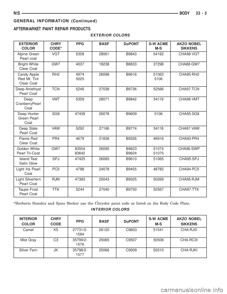
AFTERMARKET PAINT REPAIR PRODUCTS
EXTERIOR COLORS
EXTERIOR
COLORCHRY
CODE*PPG BASF DuPONT S-W ACME
M-SAKZO NOBEL
SIKKENS
Alpine Green
Pearl coatVGT 5358 28061 B9843 54162 CHA98´VGT
Bright White
Clear CoatGW7 4037 18238 B8833 37298 CHA88´GW7
Candy Apple
Red Mt. Tint
Clear CoatRH2 4974
502526098 B9616 51063
5106CHA95´RH2
Deep Amethyst
Pearl CoatTCN 5246 27038 B9736 52566 CHA97´TCN
Deep
CranberryPearl
CoatVMT 5359 28071 B9842 54119 CHA98´VMT
Deep Hunter
Green Pearl
CoatSG8 47439 26078 B9609 5106 CHA95´SG8
Deep Slate
Pearl CoatVAW 5292 27166 B9774 54118 CHA97´VAW
Flame Red
Clear CoatPR4 4679 21836 B9326 46916 CHA93´PR4
Golden White
Pearl Tri-CoatGW7 83554
8364226095 B9623
B962451074
51075CHA96´SWP
Island Teal
Satin GlowSPJ 47425 26085 B9610 51065 CHA95´SPJ
Light Iris Pearl
CoatPC5 4788 24078 B9455 48782 CHA94´PC5
Light Silverfern
Pearl CoatRJM 47383 25043 B9525 50269 CHA95´RJM
Taupe Frost
Pearl CoatTTK 5244 27040 B9750 52567 CHA97´TTK
*Herberts Standox and Spies Hecker use the Chrysler paint code as listed on the Body Code Plate.
INTERIOR COLORS
INTERIOR
COLORCHRY
CODEPPG BASF DuPONTS-W ACME
M-SAKZO NOBEL
SIKKENS
Camel K5 27731/2-
158426120 C9603 51541 CHA´RJ5I
Mist Gray C3 35799/2-
157625065 C9507 50508 CHA´RC3I
Silver Fern JK 35798/2-
157725066 C9509 50510 CHA´RJKI
NSBODY 23 - 3
GENERAL INFORMATION (Continued)
Page 1734 of 1938

STATIONARY GLASS
INDEX
page page
DESCRIPTION AND OPERATION
SAFETY PRECAUTIONS................... 4
REMOVAL AND INSTALLATION
BODY SIDE/SLIDING DOOR STATIONARY
GLASS............................... 6REAR WINDOW.......................... 7
WINDSHIELD............................ 4
DESCRIPTION AND OPERATION
SAFETY PRECAUTIONS
WARNING: DO NOT OPERATE THE VEHICLE
WITHIN 24 HOURS OF WINDSHIELD INSTALLATION.
IT TAKES AT LEAST 24 HOURS FOR URETHANE
ADHESIVE TO CURE. IF IT IS NOT CURED, THE
WINDSHIELD MAY NOT PERFORM PROPERLY IN
AN ACCIDENT.
URETHANE ADHESIVES ARE APPLIED AS A SYS-
TEM. USE GLASS CLEANER, GLASS PREP SOL-
VENT, GLASS PRIMER, PVC (VINYL) PRIMER AND
PINCHWELD (FENCE) PRIMER PROVIDED BY THE
ADHESIVE MANUFACTURER. IF NOT, STRUCTURAL
INTEGRITY COULD BE COMPROMISED.
CHRYSLER DOES NOT RECOMMEND GLASS
ADHESIVE BY BRAND. TECHNICIANS SHOULD
REVIEW PRODUCT LABELS AND TECHNICAL DATA
SHEETS, AND USE ONLY ADHESIVES THAT THEIR
MANUFACTURES WARRANT WILL RESTORE A
VEHICLE TO THE REQUIREMENTS OF FMVSS 212.
TECHNICIANS SHOULD ALSO INSURE THAT PRIM-
ERS AND CLEANERS ARE COMPATIBLE WITH THE
PARTICULAR ADHESIVE USED.
BE SURE TO REFER TO THE URETHANE MANU-
FACTURER'S DIRECTIONS FOR CURING TIME
SPECIFICATIONS, AND DO NOT USE ADHESIVE
AFTER ITS EXPIRATION DATE.
VAPORS THAT ARE EMITTED FROM THE URE-
THANE ADHESIVE OR PRIMER COULD CAUSE
PERSONAL INJURY. USE THEM IN A WELL-VENTI-
LATED AREA.
SKIN CONTACT WITH URETHANE ADHESIVE
SHOULD BE AVOIDED. PERSONAL INJURY MAY
RESULT.
ALWAYS WEAR EYE AND HAND PROTECTION
WHEN WORKING WITH GLASS.
CAUTION: Protect all painted and trimmed surfaces
from coming in contact with urethane or primers.Be careful not to damage painted surfaces when
removing moldings or cutting urethane around
windshield.
It is difficult to salvage a windshield during the
removal operation. The windshield is part of the
structural support for the roof. The urethane bonding
used to secure the windshield to the fence is difficult
to cut or clean from any surface. If the moldings are
set in urethane, it would also be unlikely they could
be salvaged. Before removing the windshield, check
the availability of the windshield and moldings from
the parts supplier.
REMOVAL AND INSTALLATION
WINDSHIELD
The urethane adhesive holding the windshield to
the opening pinch weld (fence) can be cut using a
sharp cold knife from the exterior of the vehicle.
Using the cold knife method is effective if the wind-
shield is already broken. If the glass must be sal-
vaged, cutting the urethane adhesive from the
interior of the vehicle using a reciprocating or oscil-
lating power knife is recommended.
WINDSHIELD REMOVAL ± EXTERIOR METHOD
(1) Remove inside rear view mirror.
(2) Remove windshield wiper arms.
(3) Remove cowl cover.
(4) Remove A-pillar trim panels.
(5) Disconnect wire connectors to windshield
defroster grid.
(6) Place protective covers over instrument panel
and hood.
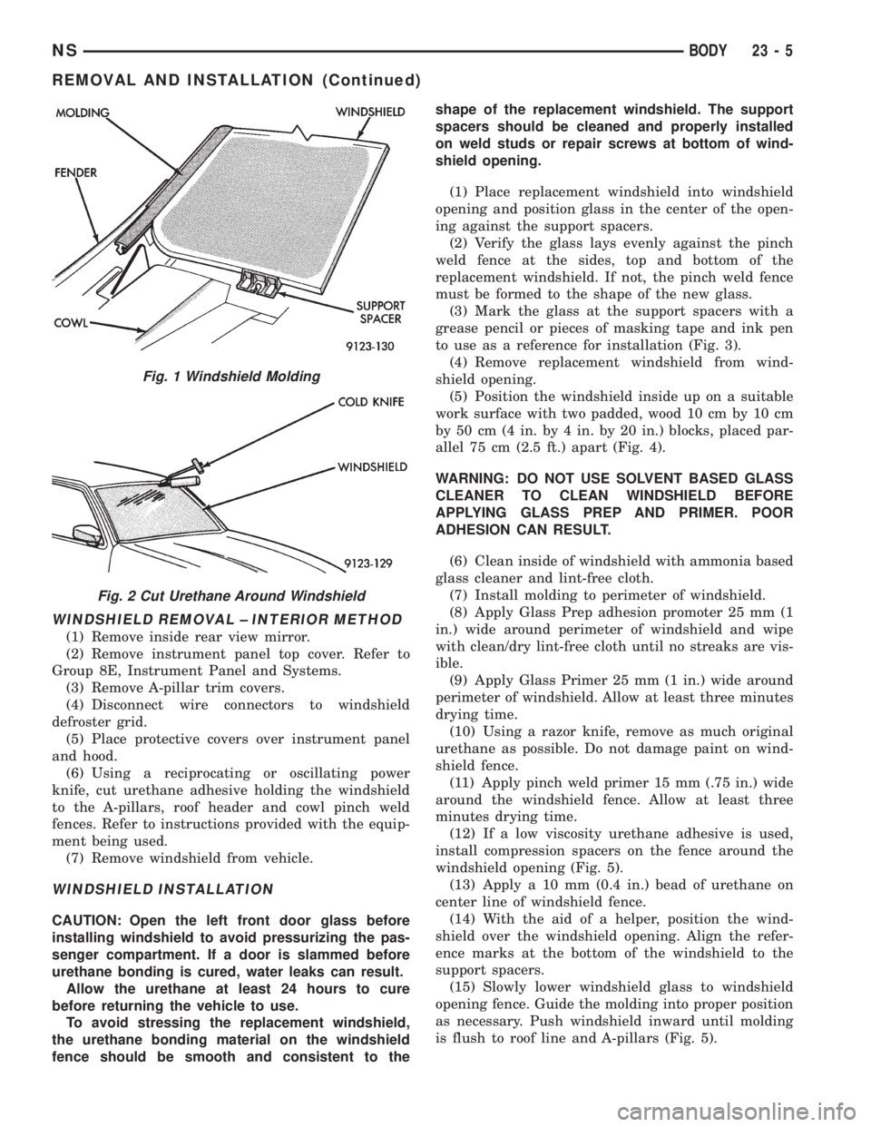
(7) Remove windshield molding (Fig. 1). Using pli-
ers, pull outward on molding at the bottom of A-pil-
lars.
(8) Using a sharp cold knife, cut urethane adhe-
sive holding the windshield to the A-pillars, roof
header and cowl pinch weld fences (Fig. 2). A power
cutting device can be used if available.
(9) Remove windshield from vehicle.
23 - 4 BODYNS
Page 1735 of 1938
WINDSHIELD REMOVAL ± INTERIOR METHOD
(1) Remove inside rear view mirror.
(2) Remove instrument panel top cover. Refer to
Group 8E, Instrument Panel and Systems.
(3) Remove A-pillar trim covers.
(4) Disconnect wire connectors to windshield
defroster grid.
(5) Place protective covers over instrument panel
and hood.
(6) Using a reciprocating or oscillating power
knife, cut urethane adhesive holding the windshield
to the A-pillars, roof header and cowl pinch weld
fences. Refer to instructions provided with the equip-
ment being used.
(7) Remove windshield from vehicle.
WINDSHIELD INSTALLATION
CAUTION: Open the left front door glass before
installing windshield to avoid pressurizing the pas-
senger compartment. If a door is slammed before
urethane bonding is cured, water leaks can result.
Allow the urethane at least 24 hours to cure
before returning the vehicle to use.
To avoid stressing the replacement windshield,
the urethane bonding material on the windshield
fence should be smooth and consistent to theshape of the replacement windshield. The support
spacers should be cleaned and properly installed
on weld studs or repair screws at bottom of wind-
shield opening.
(1) Place replacement windshield into windshield
opening and position glass in the center of the open-
ing against the support spacers.
(2) Verify the glass lays evenly against the pinch
weld fence at the sides, top and bottom of the
replacement windshield. If not, the pinch weld fence
must be formed to the shape of the new glass.
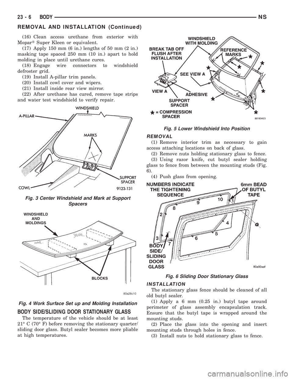
(3) Mark the glass at the support spacers with a
grease pencil or pieces of masking tape and ink pen
to use as a reference for installation (Fig. 3).
(4) Remove replacement windshield from wind-
shield opening.
(5) Position the windshield inside up on a suitable
work surface with two padded, wood 10 cm by 10 cm
by 50 cm (4 in. by 4 in. by 20 in.) blocks, placed par-
allel 75 cm (2.5 ft.) apart (Fig. 4).
WARNING: DO NOT USE SOLVENT BASED GLASS
CLEANER TO CLEAN WINDSHIELD BEFORE
APPLYING GLASS PREP AND PRIMER. POOR
ADHESION CAN RESULT.
(6) Clean inside of windshield with ammonia based
glass cleaner and lint-free cloth.
(7) Install molding to perimeter of windshield.
(8) Apply Glass Prep adhesion promoter 25 mm (1
in.) wide around perimeter of windshield and wipe
with clean/dry lint-free cloth until no streaks are vis-
ible.
(9) Apply Glass Primer 25 mm (1 in.) wide around
perimeter of windshield. Allow at least three minutes
drying time.
(10) Using a razor knife, remove as much original
urethane as possible. Do not damage paint on wind-
shield fence.
(11) Apply pinch weld primer 15 mm (.75 in.) wide
around the windshield fence. Allow at least three
minutes drying time.
(12) If a low viscosity urethane adhesive is used,
install compression spacers on the fence around the
windshield opening (Fig. 5).
(13) Apply a 10 mm (0.4 in.) bead of urethane on
center line of windshield fence.
(14) With the aid of a helper, position the wind-
shield over the windshield opening. Align the refer-
ence marks at the bottom of the windshield to the
support spacers.
(15) Slowly lower windshield glass to windshield
opening fence. Guide the molding into proper position
as necessary. Push windshield inward until molding
is flush to roof line and A-pillars (Fig. 5).
Fig. 1 Windshield Molding
Fig. 2 Cut Urethane Around Windshield
NSBODY 23 - 5
REMOVAL AND INSTALLATION (Continued)
Page 1736 of 1938
(16) Clean access urethane from exterior with
MopartSuper Kleen or equivalent.
(17) Apply 150 mm (6 in.) lengths of 50 mm (2 in.)
masking tape spaced 250 mm (10 in.) apart to hold
molding in place until urethane cures.
(18) Engage wire connectors to windshield
defroster grid.
(19) Install A-pillar trim panels.
(20) Install cowl cover and wipers.
(21) Install inside rear view mirror.
(22) After urethane has cured, remove tape strips
and water test windshield to verify repair.
BODY SIDE/SLIDING DOOR STATIONARY GLASS
The temperature of the vehicle should be at least
21É C (70É F) before removing the stationary quarter/
sliding door glass. Butyl sealer becomes more pliable
at high temperatures.
REMOVAL
(1) Remove interior trim as necessary to gain
access attaching locations on back of glass.
(2) Remove nuts holding stationary glass to fence.
(3) Using razor knife, cut butyl sealer holding
glass to fence from between the mounting studs (Fig.
6).
(4) Push glass from opening.
INSTALLATION
The stationary glass fence should be cleaned of all
old butyl sealer.
(1) Applya6mm(0.25 in.) butyl tape around
perimeter of glass assembly encapsulation track.
Ensure that the butyl tape is wrapped around the
mounting studs.
(2) Place the glass into the opening and insert
mounting studs through holes in fence.
(3) Install nuts to hold stationary glass to fence.
Fig. 3 Center Windshield and Mark at Support
Spacers
Fig. 4 Work Surface Set up and Molding Installation
Fig. 5 Lower Windshield Into Position
Fig. 6 Sliding Door Stationary Glass
23 - 6 BODYNS
REMOVAL AND INSTALLATION (Continued)
Page 1737 of 1938
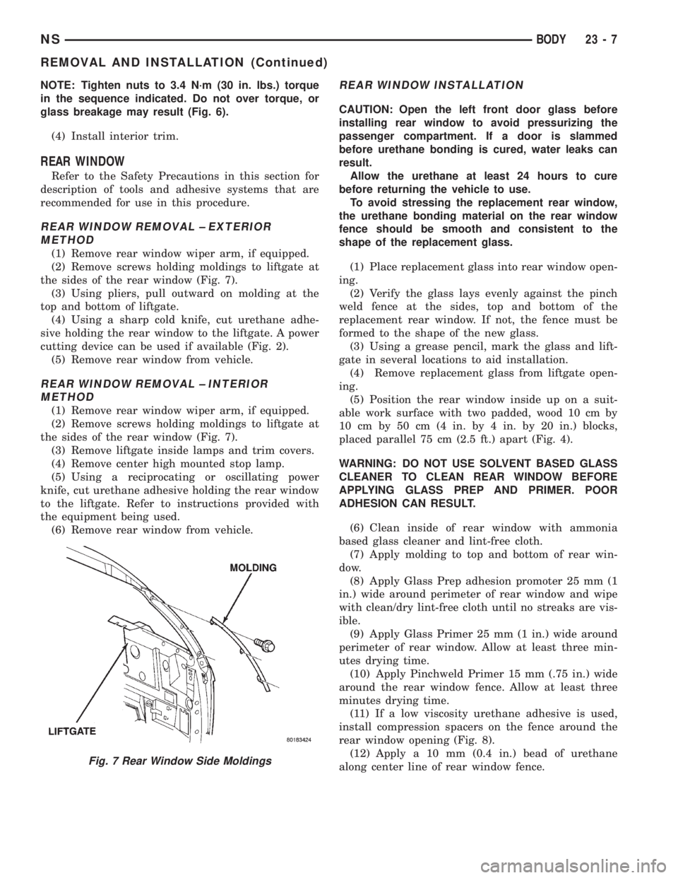
NOTE: Tighten nuts to 3.4 N´m (30 in. lbs.) torque
in the sequence indicated. Do not over torque, or
glass breakage may result (Fig. 6).
(4) Install interior trim.
REAR WINDOW
Refer to the Safety Precautions in this section for
description of tools and adhesive systems that are
recommended for use in this procedure.
REAR WINDOW REMOVAL ± EXTERIOR
METHOD
(1) Remove rear window wiper arm, if equipped.
(2) Remove screws holding moldings to liftgate at
the sides of the rear window (Fig. 7).
(3) Using pliers, pull outward on molding at the
top and bottom of liftgate.
(4) Using a sharp cold knife, cut urethane adhe-
sive holding the rear window to the liftgate. A power
cutting device can be used if available (Fig. 2).
(5) Remove rear window from vehicle.
REAR WINDOW REMOVAL ± INTERIOR
METHOD
(1) Remove rear window wiper arm, if equipped.
(2) Remove screws holding moldings to liftgate at
the sides of the rear window (Fig. 7).
(3) Remove liftgate inside lamps and trim covers.
(4) Remove center high mounted stop lamp.
(5) Using a reciprocating or oscillating power
knife, cut urethane adhesive holding the rear window
to the liftgate. Refer to instructions provided with
the equipment being used.
(6) Remove rear window from vehicle.
REAR WINDOW INSTALLATION
CAUTION: Open the left front door glass before
installing rear window to avoid pressurizing the
passenger compartment. If a door is slammed
before urethane bonding is cured, water leaks can
result.
Allow the urethane at least 24 hours to cure
before returning the vehicle to use.
To avoid stressing the replacement rear window,
the urethane bonding material on the rear window
fence should be smooth and consistent to the
shape of the replacement glass.
(1) Place replacement glass into rear window open-
ing.
(2) Verify the glass lays evenly against the pinch
weld fence at the sides, top and bottom of the
replacement rear window. If not, the fence must be
formed to the shape of the new glass.
(3) Using a grease pencil, mark the glass and lift-
gate in several locations to aid installation.
(4) Remove replacement glass from liftgate open-
ing.
(5) Position the rear window inside up on a suit-
able work surface with two padded, wood 10 cm by
10 cm by 50 cm (4 in. by 4 in. by 20 in.) blocks,
placed parallel 75 cm (2.5 ft.) apart (Fig. 4).
WARNING: DO NOT USE SOLVENT BASED GLASS
CLEANER TO CLEAN REAR WINDOW BEFORE
APPLYING GLASS PREP AND PRIMER. POOR
ADHESION CAN RESULT.
(6) Clean inside of rear window with ammonia
based glass cleaner and lint-free cloth.
(7) Apply molding to top and bottom of rear win-
dow.
(8) Apply Glass Prep adhesion promoter 25 mm (1
in.) wide around perimeter of rear window and wipe
with clean/dry lint-free cloth until no streaks are vis-
ible.
(9) Apply Glass Primer 25 mm (1 in.) wide around
perimeter of rear window. Allow at least three min-
utes drying time.
(10) Apply Pinchweld Primer 15 mm (.75 in.) wide
around the rear window fence. Allow at least three
minutes drying time.
(11) If a low viscosity urethane adhesive is used,
install compression spacers on the fence around the
rear window opening (Fig. 8).
(12) Apply a 10 mm (0.4 in.) bead of urethane
along center line of rear window fence.
Fig. 7 Rear Window Side Moldings
NSBODY 23 - 7
REMOVAL AND INSTALLATION (Continued)
Page 1738 of 1938
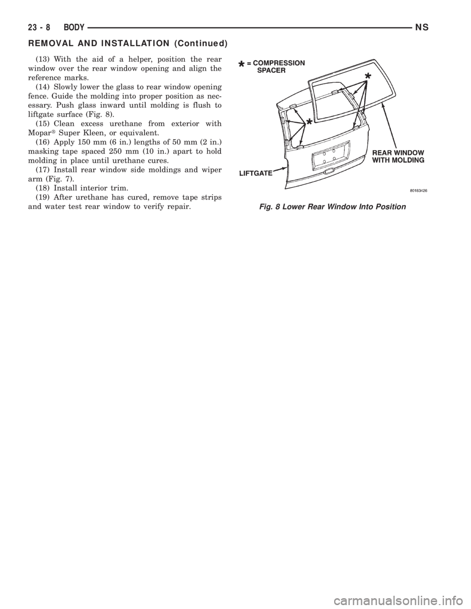
(13) With the aid of a helper, position the rear
window over the rear window opening and align the
reference marks.
(14) Slowly lower the glass to rear window opening
fence. Guide the molding into proper position as nec-
essary. Push glass inward until molding is flush to
liftgate surface (Fig. 8).
(15) Clean excess urethane from exterior with
MopartSuper Kleen, or equivalent.
(16) Apply 150 mm (6 in.) lengths of 50 mm (2 in.)
masking tape spaced 250 mm (10 in.) apart to hold
molding in place until urethane cures.
(17) Install rear window side moldings and wiper
arm (Fig. 7).
(18) Install interior trim.
(19) After urethane has cured, remove tape strips
and water test rear window to verify repair.
Fig. 8 Lower Rear Window Into Position
23 - 8 BODYNS
REMOVAL AND INSTALLATION (Continued)
Page 1739 of 1938
SEATS
INDEX
page page
REMOVAL AND INSTALLATION
ARM REST.............................. 9
BENCH SEAT BACK COVER................ 9
BENCH SEAT BACK HINGE COVERS........ 10
BENCH SEAT BACK HINGE................. 9
BENCH SEAT RISER ± FIRST REAR......... 11
BENCH SEAT RISER ± SECOND REAR....... 11
BENCH SEAT TRACK ± SECOND REAR...... 11
BUCKET SEAT BACK ASSIST STRAP........ 12
BUCKET SEAT BACK..................... 12
BUCKET SEAT CUSHION PAN.............. 12
BUCKET SEAT CUSHION SIDE COVER....... 13
BUCKET SEAT RECLINER ± MANUAL........ 13
BUCKET SEAT RECLINER ± POWER......... 14
BUCKET SEAT RISER ± MANUAL TRACK..... 14
BUCKET SEAT TRACK FRONT COVER ±
POWER.............................. 15BUCKET SEAT TRACK REAR COVER ±
POWER.............................. 15
BUCKET SEAT TRACK ± MANUAL........... 14
BUCKET SEAT TRACK ± POWER........... 14
CHILD RESTRAINT SEAT MODULE.......... 16
HEAD RESTRAINT SLEEVE................ 18
HEAD RESTRAINT ± BENCH SEAT.......... 16
HEAD RESTRAINT ± BUCKET SEAT......... 17
HEATED SEAT HEATING ELEMENT.......... 18
HEATED SEAT MODULE.................. 18
HEATED SEAT SWITCH................... 19
MECHANICAL LUMBAR HANDLE ASSEMBLY . . 19
PLASTIC GROCERY BAG RETAINER......... 19
POWER SEAT SWITCH................... 20
RECLINER HANDLE ± MANUAL............. 20
UNDER SEAT STORAGE BIN GUIDE......... 21
UNDER SEAT STORAGE BIN LOCK/LATCH.... 21
UNDER SEAT STORAGE BIN............... 20
REMOVAL AND INSTALLATION
ARM REST
REMOVAL
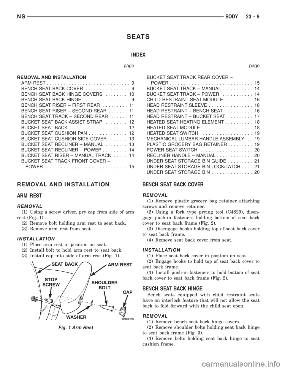
(1) Using a screw driver, pry cap from side of arm
rest (Fig. 1).
(2) Remove bolt holding arm rest to seat back.
(3) Remove arm rest from seat.
INSTALLATION
(1) Place arm rest in position on seat.
(2) Install bolt to hold arm rest to seat back.
(3) Install cap into side of arm rest (Fig. 1).
BENCH SEAT BACK COVER
REMOVAL
(1) Remove plastic grocery bag retainer attaching
screws and remove retainer.
(2) Using a fork type prying tool (C4829), disen-
gage push-in fasteners holding bottom of seat back
cover to seat back frame (Fig. 2).
(3) Disengage hooks holding top of seat back cover
to seat back frame.
(4) Remove seat back cover from seat.
INSTALLATION
(1) Place seat back cover in position on seat.
(2) Engage hooks to hold top of seat back cover to
seat back frame.
(3) Install push-in fasteners to hold bottom of seat
back cover to seat back frame (Fig. 2).
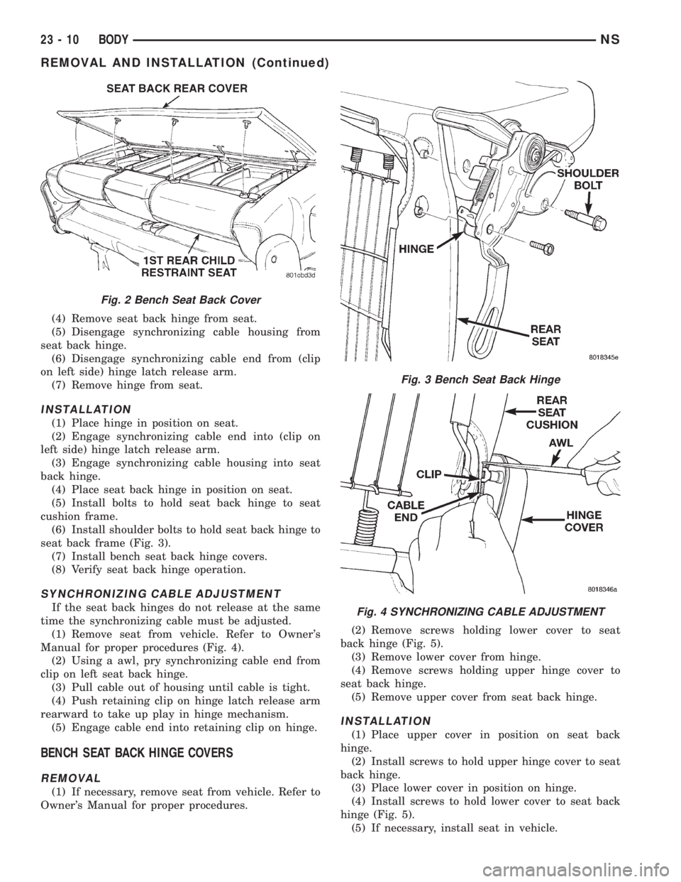
BENCH SEAT BACK HINGE
Bench seats equipped with child restraint seats
have an interlock feature that will not allow the seat
back to fold forward with the child seat open.
REMOVAL
(1) Remove bench seat back hinge covers.
(2) Remove shoulder bolts holding seat back hinge
to seat back frame (Fig. 3).
(3) Remove bolts holding seat back hinge to seat
cushion frame.
Fig. 1 Arm Rest
NSBODY 23 - 9
Page 1740 of 1938
(4) Remove seat back hinge from seat.
(5) Disengage synchronizing cable housing from
seat back hinge.
(6) Disengage synchronizing cable end from (clip
on left side) hinge latch release arm.
(7) Remove hinge from seat.
INSTALLATION
(1) Place hinge in position on seat.
(2) Engage synchronizing cable end into (clip on
left side) hinge latch release arm.
(3) Engage synchronizing cable housing into seat
back hinge.
(4) Place seat back hinge in position on seat.
(5) Install bolts to hold seat back hinge to seat
cushion frame.
(6) Install shoulder bolts to hold seat back hinge to
seat back frame (Fig. 3).
(7) Install bench seat back hinge covers.
(8) Verify seat back hinge operation.
SYNCHRONIZING CABLE ADJUSTMENT
If the seat back hinges do not release at the same
time the synchronizing cable must be adjusted.
(1) Remove seat from vehicle. Refer to Owner's
Manual for proper procedures (Fig. 4).
(2) Using a awl, pry synchronizing cable end from
clip on left seat back hinge.
(3) Pull cable out of housing until cable is tight.
(4) Push retaining clip on hinge latch release arm
rearward to take up play in hinge mechanism.
(5) Engage cable end into retaining clip on hinge.
BENCH SEAT BACK HINGE COVERS
REMOVAL
(1) If necessary, remove seat from vehicle. Refer to
Owner's Manual for proper procedures.(2) Remove screws holding lower cover to seat
back hinge (Fig. 5).
(3) Remove lower cover from hinge.
(4) Remove screws holding upper hinge cover to
seat back hinge.
(5) Remove upper cover from seat back hinge.
INSTALLATION
(1) Place upper cover in position on seat back
hinge.
(2) Install screws to hold upper hinge cover to seat
back hinge.
(3) Place lower cover in position on hinge.
(4) Install screws to hold lower cover to seat back
hinge (Fig. 5).
(5) If necessary, install seat in vehicle.
Fig. 2 Bench Seat Back Cover
Fig. 3 Bench Seat Back Hinge
Fig. 4 SYNCHRONIZING CABLE ADJUSTMENT
23 - 10 BODYNS
REMOVAL AND INSTALLATION (Continued)