CHRYSLER VOYAGER 1996 Service Manual
Manufacturer: CHRYSLER, Model Year: 1996, Model line: VOYAGER, Model: CHRYSLER VOYAGER 1996Pages: 1938, PDF Size: 55.84 MB
Page 1701 of 1938
(3) Install the synchro springs into the synchro
struts.
(4) Line up stop ring tang over the struts in the
hub. Install stop rings. Center the struts by pushing
on both stop rings.
(5) Install the outer cones (dual-cone synchronizer)
into the synchronizer stop rings.
(6) Install the inner cones (dual-cone synchronizer)
into the outer cones.
SHIFT COVER
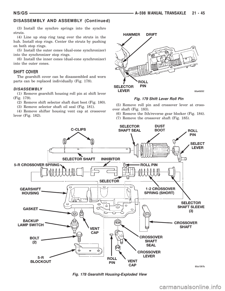
The gearshift cover can be disassembled and worn
parts can be replaced individually (Fig. 178).
DISASSEMBLY
(1) Remove gearshift housing roll pin at shift lever
(Fig. 179).
(2) Remove shift selector shaft dust boot (Fig. 180).
(3) Remove selector shaft oil seal (Fig. 181).
(4) Remove shifter housing vent cap at crossover
lever (Fig. 182).(5) Remove roll pin and crossover lever at cross-
over shaft (Fig. 183).
(6) Remove the 5th/reverse gear blocker (Fig. 184).
(7) Remove the crossover shaft (Fig. 185).
Fig. 178 Gearshift Housing-Exploded View
Fig. 179 Shift Lever Roll Pin
NS/GSA±598 MANUAL TRANSAXLE 21 - 45
DISASSEMBLY AND ASSEMBLY (Continued)
Page 1702 of 1938
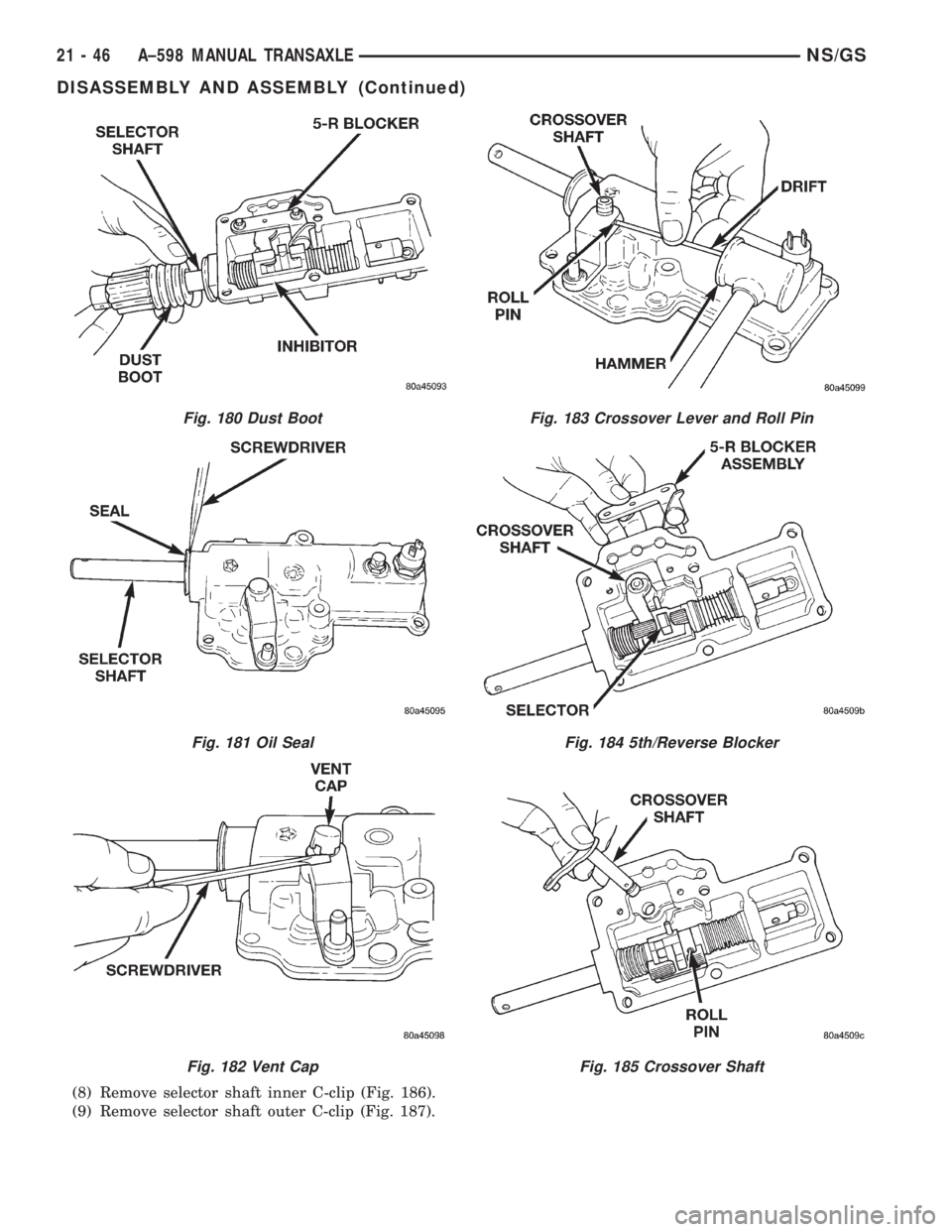
(8) Remove selector shaft inner C-clip (Fig. 186).
(9) Remove selector shaft outer C-clip (Fig. 187).
Fig. 180 Dust Boot
Fig. 181 Oil Seal
Fig. 182 Vent Cap
Fig. 183 Crossover Lever and Roll Pin
Fig. 184 5th/Reverse Blocker
Fig. 185 Crossover Shaft
21 - 46 A±598 MANUAL TRANSAXLENS/GS
DISASSEMBLY AND ASSEMBLY (Continued)
Page 1703 of 1938
NOTE: Drive roll pin out far enough to clear the
selector shaft, but not through. The pin must
remain in the selector so not to break the housing.
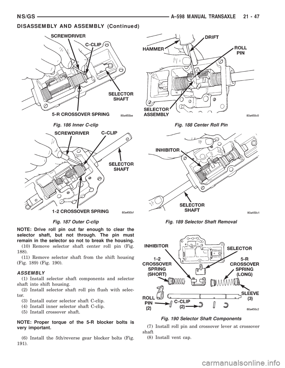
(10) Remove selector shaft center roll pin (Fig.
188).
(11) Remove selector shaft from the shift housing
(Fig. 189) (Fig. 190).
ASSEMBLY
(1) Install selector shaft components and selector
shaft into shift housing.
(2) Install selector shaft roll pin flush with selec-
tor.
(3) Install outer selector shaft C-clip.
(4) Install inner selector shaft C-clip.
(5) Install crossover shaft.
NOTE: Proper torque of the 5-R blocker bolts is
very important.
(6) Install the 5th/reverse gear blocker bolts (Fig.
191).(7) Install roll pin and crossover lever at crossover
shaft
(8) Install vent cap.
Fig. 186 Inner C-clip
Fig. 187 Outer C-clip
Fig. 188 Center Roll Pin
Fig. 189 Selector Shaft Removal
Fig. 190 Selector Shaft Components
NS/GSA±598 MANUAL TRANSAXLE 21 - 47
DISASSEMBLY AND ASSEMBLY (Continued)
Page 1704 of 1938
NOTE: The C-Clip grooves in the selector shaft will
damage the oil seal. Install oil seal after selector
shaft is installed. Always use a new oil seal when
selector shaft is removed.
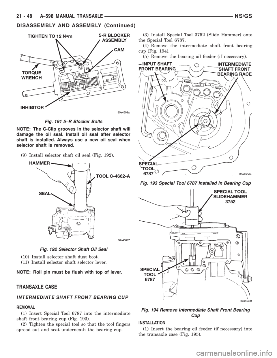
(9) Install selector shaft oil seal (Fig. 192).
(10) Install selector shaft dust boot.
(11) Install selector shaft selector lever.
NOTE: Roll pin must be flush with top of lever.
TRANSAXLE CASE
INTERMEDIATE SHAFT FRONT BEARING CUP
REMOVAL
(1) Insert Special Tool 6787 into the intermediate
shaft front bearing cup (Fig. 193).
(2) Tighten the special tool so that the tool fingers
spread out and seat underneath the bearing cup.(3) Install Special Tool 3752 (Slide Hammer) onto
the Special Tool 6787.
(4) Remove the intermediate shaft front bearing
cup (Fig. 194).
(5) Remove the bearing oil feeder (if necessary).
INSTALLATION
(1) Insert the bearing oil feeder (if necessary) into
the transaxle case (Fig. 195).
Fig. 191 5±R Blocker Bolts
Fig. 192 Selector Shaft Oil Seal
Fig. 193 Special Tool 6787 Installed in Bearing Cup
Fig. 194 Remove Intermediate Shaft Front Bearing
Cup
21 - 48 A±598 MANUAL TRANSAXLENS/GS
DISASSEMBLY AND ASSEMBLY (Continued)
Page 1705 of 1938
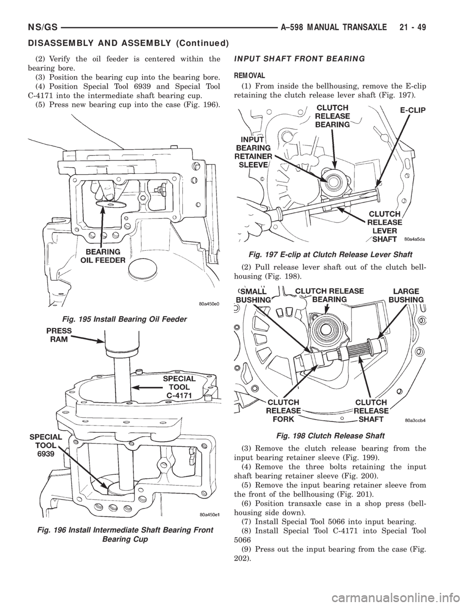
(2) Verify the oil feeder is centered within the
bearing bore.
(3) Position the bearing cup into the bearing bore.
(4) Position Special Tool 6939 and Special Tool
C-4171 into the intermediate shaft bearing cup.
(5) Press new bearing cup into the case (Fig. 196).INPUT SHAFT FRONT BEARING
REMOVAL
(1) From inside the bellhousing, remove the E-clip
retaining the clutch release lever shaft (Fig. 197).
(2) Pull release lever shaft out of the clutch bell-
housing (Fig. 198).
(3) Remove the clutch release bearing from the
input bearing retainer sleeve (Fig. 199).
(4) Remove the three bolts retaining the input
shaft bearing retainer sleeve (Fig. 200).
(5) Remove the input bearing retainer sleeve from
the front of the bellhousing (Fig. 201).
(6) Position transaxle case in a shop press (bell-
housing side down).
(7) Install Special Tool 5066 into input bearing.
(8) Install Special Tool C-4171 into Special Tool
5066
(9) Press out the input bearing from the case (Fig.
202).
Fig. 196 Install Intermediate Shaft Bearing Front
Bearing Cup
Fig. 195 Install Bearing Oil Feeder
Fig. 197 E-clip at Clutch Release Lever Shaft
Fig. 198 Clutch Release Shaft
NS/GSA±598 MANUAL TRANSAXLE 21 - 49
DISASSEMBLY AND ASSEMBLY (Continued)
Page 1706 of 1938
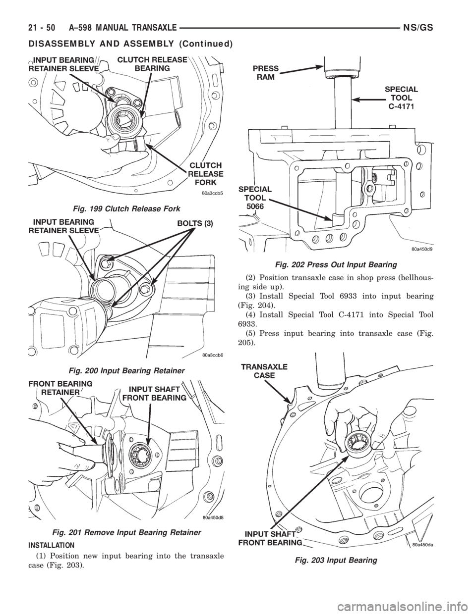
INSTALLATION
(1) Position new input bearing into the transaxle
case (Fig. 203).(2) Position transaxle case in shop press (bellhous-
ing side up).
(3) Install Special Tool 6933 into input bearing
(Fig. 204).
(4) Install Special Tool C-4171 into Special Tool
6933.
(5) Press input bearing into transaxle case (Fig.
205).
Fig. 199 Clutch Release Fork
Fig. 200 Input Bearing Retainer
Fig. 201 Remove Input Bearing Retainer
Fig. 202 Press Out Input Bearing
Fig. 203 Input Bearing
21 - 50 A±598 MANUAL TRANSAXLENS/GS
DISASSEMBLY AND ASSEMBLY (Continued)
Page 1707 of 1938
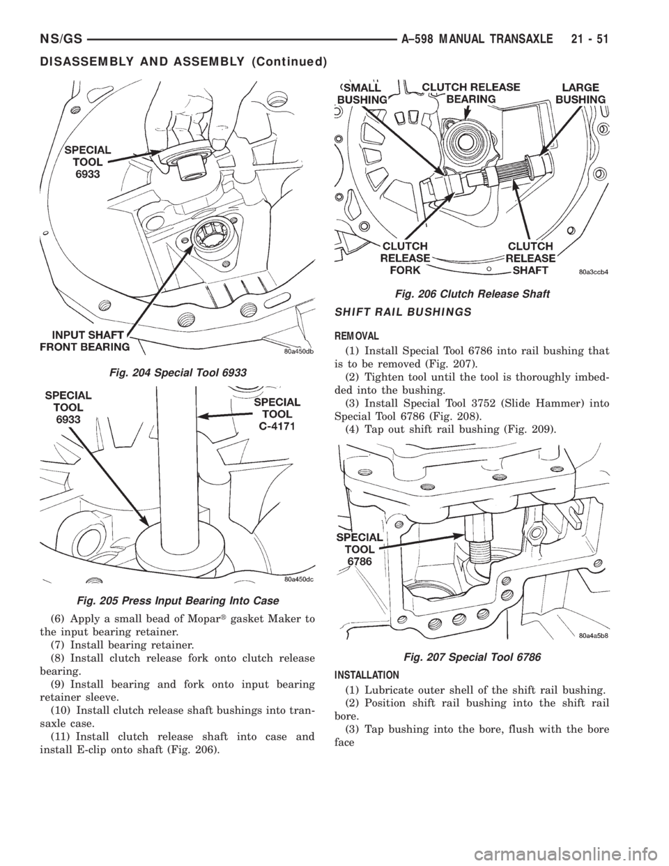
(6) Apply a small bead of Mopartgasket Maker to
the input bearing retainer.
(7) Install bearing retainer.
(8) Install clutch release fork onto clutch release
bearing.
(9) Install bearing and fork onto input bearing
retainer sleeve.
(10) Install clutch release shaft bushings into tran-
saxle case.
(11) Install clutch release shaft into case and
install E-clip onto shaft (Fig. 206).
SHIFT RAIL BUSHINGS
REMOVAL
(1) Install Special Tool 6786 into rail bushing that
is to be removed (Fig. 207).
(2) Tighten tool until the tool is thoroughly imbed-
ded into the bushing.
(3) Install Special Tool 3752 (Slide Hammer) into
Special Tool 6786 (Fig. 208).
(4) Tap out shift rail bushing (Fig. 209).
INSTALLATION
(1) Lubricate outer shell of the shift rail bushing.
(2) Position shift rail bushing into the shift rail
bore.
(3) Tap bushing into the bore, flush with the bore
face
Fig. 204 Special Tool 6933
Fig. 205 Press Input Bearing Into Case
Fig. 206 Clutch Release Shaft
Fig. 207 Special Tool 6786
NS/GSA±598 MANUAL TRANSAXLE 21 - 51
DISASSEMBLY AND ASSEMBLY (Continued)
Page 1708 of 1938
REVERSE SHIFT LEVER
REMOVAL
(1) Remove reverse shift lever E-clip.
(2) Remove the flat and wave washers.
(3) Remove the reverse shift lever from the mount-
ing stud.
INSTALLATION
(1) Position the reverse shift lever onto the mount-
ing stud.
(2) Install the washers onto the mounting stud.
(3) Install the E-clip.
CLEANING AND INSPECTION
TRANSAXLE
Clean the gears, bearings, shafts, synchronizers,
thrust washers, oil feeder, shift mechanism, gear
case, and bellhousing with solvent. Dry all parts
except the bearings with compressed air. Allow thebearings to either air dry or wipe them dry with
clean shop towels.
Inspect the gears, bearings, shafts and thrust
washers. Replace the bearings and cups if the rollers
are worn, chipped, cracked, flat spotted, or brin-
nelled, or if the bearing cage is damaged or distorted.
Replace the thrust washers if cracked, chipped, or
worn. Replace the gears if the teeth are chipped,
cracked, or worn thin. Inspect the synchronizers.
Replace the sleeve if worn or damaged in any way.
Replace the stop rings if the friction material is
burned, flaking off, or worn. Check the condition of
the synchro struts and springs. Replace these parts if
worn, cracked, or distorted.
SYNCHRONIZER
CLEAN
Do not attempt to clean the blocking rings in sol-
vent. The friction material will become contaminated.
Place synchronizer components in a suitable holder
and clean with solvent. Air dry.
INSPECT
Proper inspection of components involve:
²Teeth, for wear, scuffed, nicked, burred, or bro-
ken teeth
²Struts, for wear or distortion
²Springs, for distortion, cracks, or wear
If any of these conditions exist in these compo-
nents, replace as necessary.
ADJUSTMENTS
GEARSHIFT CROSSOVER CABLE
Before replacing the gearshift cables for a hard-
shifting complaint, disconnect both cables at the
transaxle. Then, from the driver's seat, manually
operate the gearshift lever through all gear ranges. If
the gearshift lever moves smoothly, the cable(s)
should NOT be replaced. If the gear lever binds
replace the cable that is causing the binding condi-
tion. If the problem still exists, check the crossover
cable adjustment (Fig. 210).
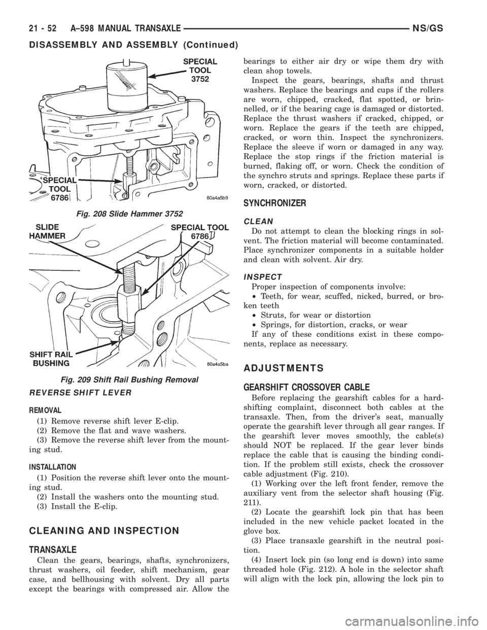
(1) Working over the left front fender, remove the
auxiliary vent from the selector shaft housing (Fig.
211).
(2) Locate the gearshift lock pin that has been
included in the new vehicle packet located in the
glove box.
(3) Place transaxle gearshift in the neutral posi-
tion.
(4) Insert lock pin (so long end is down) into same
threaded hole (Fig. 212). A hole in the selector shaft
will align with the lock pin, allowing the lock pin to
Fig. 208 Slide Hammer 3752
Fig. 209 Shift Rail Bushing Removal
21 - 52 A±598 MANUAL TRANSAXLENS/GS
DISASSEMBLY AND ASSEMBLY (Continued)
Page 1709 of 1938
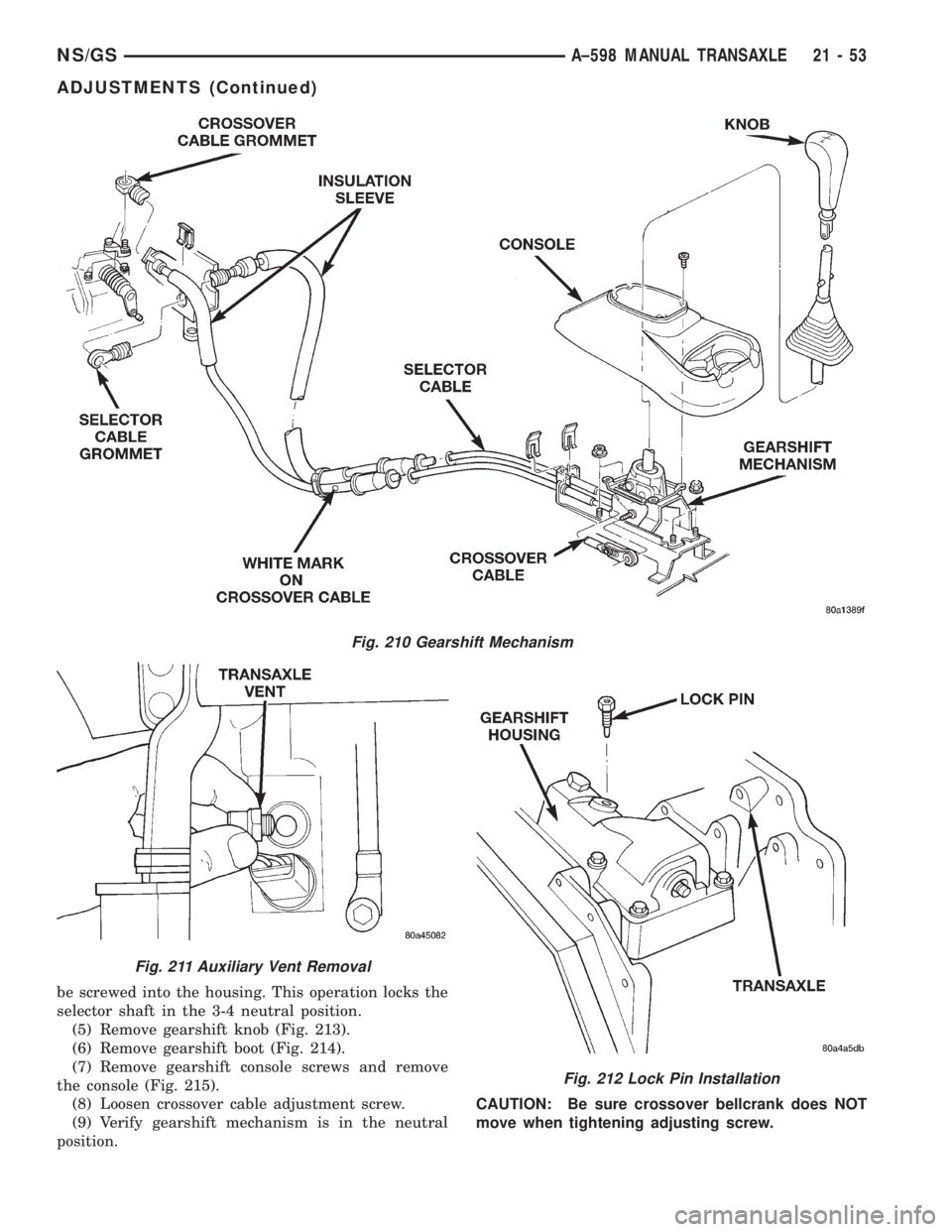
be screwed into the housing. This operation locks the
selector shaft in the 3-4 neutral position.
(5) Remove gearshift knob (Fig. 213).
(6) Remove gearshift boot (Fig. 214).
(7) Remove gearshift console screws and remove
the console (Fig. 215).
(8) Loosen crossover cable adjustment screw.
(9) Verify gearshift mechanism is in the neutral
position.CAUTION: Be sure crossover bellcrank does NOT
move when tightening adjusting screw.
Fig. 210 Gearshift Mechanism
Fig. 211 Auxiliary Vent Removal
Fig. 212 Lock Pin Installation
NS/GSA±598 MANUAL TRANSAXLE 21 - 53
ADJUSTMENTS (Continued)
Page 1710 of 1938
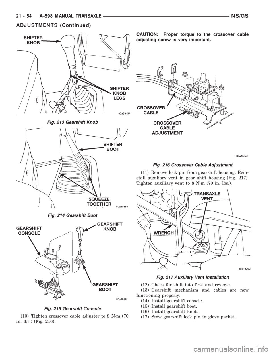
(10) Tighten crossover cable adjuster to 8 N´m (70
in. lbs.) (Fig. 216).CAUTION: Proper torque to the crossover cable
adjusting screw is very important.
(11) Remove lock pin from gearshift housing. Rein-
stall auxiliary vent in gear shift housing (Fig. 217).
Tighten auxiliary vent to 8 N´m (70 in. lbs.).
(12) Check for shift into first and reverse.
(13) Gearshift mechanism and cables are now
functioning properly.
(14) Install gearshift console.
(15) Install gearshift boot.
(16) Install gearshift knob.
(17) Stow gearshift lock pin in glove packet.
Fig. 213 Gearshift Knob
Fig. 214 Gearshift Boot
Fig. 215 Gearshift Console
Fig. 216 Crossover Cable Adjustment
Fig. 217 Auxiliary Vent Installation
21 - 54 A±598 MANUAL TRANSAXLENS/GS
ADJUSTMENTS (Continued)