coolant level CHRYSLER VOYAGER 1996 User Guide
[x] Cancel search | Manufacturer: CHRYSLER, Model Year: 1996, Model line: VOYAGER, Model: CHRYSLER VOYAGER 1996Pages: 1938, PDF Size: 55.84 MB
Page 230 of 1938

at running operating temperature the high pressure
inlet tank runs full and the low pressure outlet tank
drops:
²Transmission oil will become hotter.
²High reading shown on the temperature gauge.
²Air in the coolant can cause loss of flow through
the heater.
²Exhaust gas leaks into the coolant also can
cause the same problems.
DEAERATION
Air can only be removed from the system by gath-
ering under the pressure cap. On the next heat up it
will be pushed past the pressure cap into the CRS
tank by thermal expansion of the coolant. It then
escapes to the atmosphere in the CRS tank and is
replaced with solid coolant on cool down.
TEMPERATURE GAUGE INDICATION
At idle with Air Conditioning off the temperature
gauge will rise slowly to about 5/8 gauge travel, the
fan will come on and the gauge will quickly drop to
about 1/2 gauge travel. This is normal.
SERVICE PROCEDURES
COOLANT LEVEL CHECKÐROUTINE
Do not remove radiator cap for routine cool-
ant level inspections.
The coolant reserve system provides a quick visual
method for determining the coolant level without
removing the radiator cap.With the engine cold
and not running,simply observe the level of the
coolant in the reserve tank (Fig. 3). The coolant level
should be between the minimum and maximum
marks.
COOLANTÐADDING ADDITIONAL
The radiator cap should not be removed.
When additional coolant is needed to maintain this
level, it should be added to the coolant reserve tank.
Use only 50/50 mix of ethylene glycol type antifreeze
and water.
CAUTION: Do not use well water, or suspect water
supply in cooling system. A 50/50 ethylene glycol
and distilled water mix is recommended.
COOLANT LEVEL SERVICE
The cooling system is closed and designed to main-
tain coolant level to the top of the radiator.
When servicing requires a coolant level check in
the radiator, the engine must beoffandnotunder
pressure. Drain several ounces of coolant from the
radiator draincock while observing the CoolantRecovery System (CRS) Tank. Coolant level in the
CRS tank should drop slightly. Then remove the radi-
ator cap. The radiator should be full to the top. If
not, and the coolant level in the CRS tank is at the
MIN mark there is an air leak in the CRS system.
Check hose or hose connections to the CRS tank,
radiator filler neck or the pressure cap seal to the
radiator filler neck for leaks.
COOLING SYSTEMÐDRAINING
Without removing radiator pressure cap and
with system not under pressure,shut engine off
and open draincock. The coolant reserve tank should
empty first, then remove radiator pressure cap. (if
not, see Testing Cooling System for leaks). To vent
2.4L engine remove the coolant temperature sensor
located above water outlet housing (Fig. 15). The 3.0/
3.3/3.8L engines have an air bleed vent on the ther-
mostat.
Removal of a sensor is required because the ther-
mostat does not have an air vent. Sensor removal
allows an air bleed for coolant to drain from the
engine block.
COOLING SYSTEMÐREFILLING
First clean system to remove old coolant, see Cool-
ing System Cleaning.
Fill the system, using the correct antifreeze as
described in the Coolant Section. Fill the system to
50 percent of its capacity with 100 percent glycol.
Then complete filling system with water. The 2.4L
engine requires venting by removal of the coolant
sensor on top of the water outlet connector (Fig. 15).
When coolant reaches this hole:
²Install coolant sensor and tighten to 7 N´m (60
in. lbs.) for 2.4L Engines.
Fig. 15 Coolant Temperature SensorÐ2.4L Engine
Drain/Fill
7 - 16 COOLING SYSTEMNS
DIAGNOSIS AND TESTING (Continued)
Page 231 of 1938
Continue filling system until full, this provides bet-
ter heater performance.Be careful not to spill
coolant on drive belts or the generator.
Fill coolant reserve system to at least the MAX
mark with 50/50 solution. It may be necessary to add
coolant to the reserve tank after three or four warm
up/cool down cycles to maintain coolant level between
the MAX and MIN mark. This will allow trapped air
to be removed from the system.
REMOVAL AND INSTALLATION
WATER PUMPÐ2.4L ENGINE
REMOVAL
(1) Disconnect negative cable from battery.
(2) Raise vehicle on a hoist. Remove right inner
splash shield.
(3) Remove accessory drive belts. Refer to Acces-
sory Drive Belt service in this section.
(4) Drain cooling system. Refer to Cooling System
Draining in this section.
(5) Support engine from the bottom and remove
right engine mount.
(6) Remove right engine mount bracket.
(7) Remove timing belt. Refer to Group 9, Engine
for procedure.
(8) Remove timing belt idler pulley.
(9) Hold camshaft sprocket with Special tool
C-4687 and adaptor C-4687-1 while removing bolt.
Remove both cam sprockets.
(10) Remove rear timing belt cover.
(11) Remove water pump attaching screws to
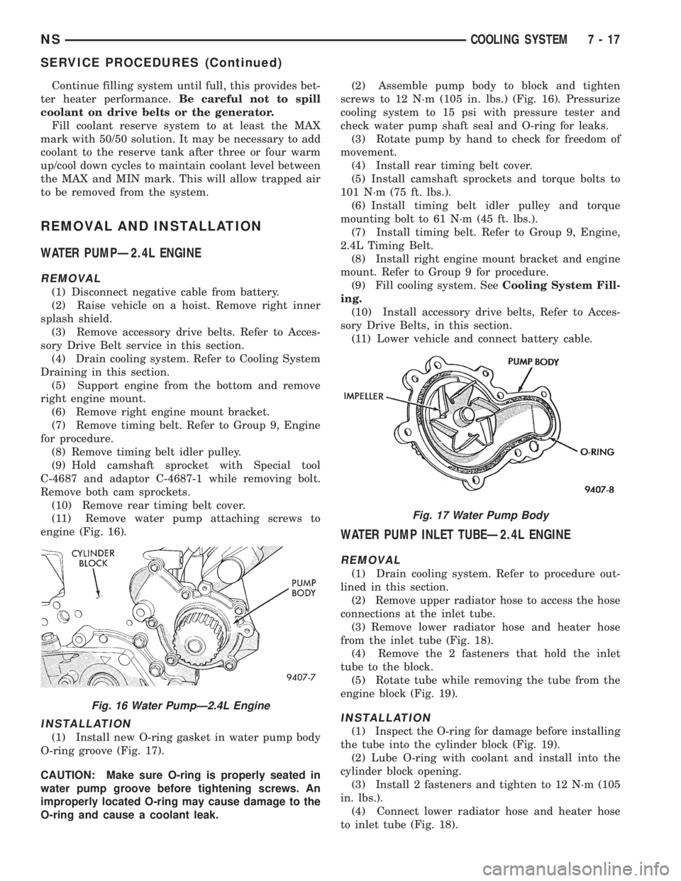
engine (Fig. 16).
INSTALLATION
(1) Install new O-ring gasket in water pump body
O-ring groove (Fig. 17).
CAUTION: Make sure O-ring is properly seated in
water pump groove before tightening screws. An
improperly located O-ring may cause damage to the
O-ring and cause a coolant leak.(2) Assemble pump body to block and tighten
screws to 12 N´m (105 in. lbs.) (Fig. 16). Pressurize
cooling system to 15 psi with pressure tester and
check water pump shaft seal and O-ring for leaks.
(3) Rotate pump by hand to check for freedom of
movement.
(4) Install rear timing belt cover.
(5) Install camshaft sprockets and torque bolts to
101 N´m (75 ft. lbs.).
(6) Install timing belt idler pulley and torque
mounting bolt to 61 N´m (45 ft. lbs.).
(7) Install timing belt. Refer to Group 9, Engine,
2.4L Timing Belt.
(8) Install right engine mount bracket and engine
mount. Refer to Group 9 for procedure.
(9) Fill cooling system. SeeCooling System Fill-
ing.
(10) Install accessory drive belts, Refer to Acces-
sory Drive Belts, in this section.
(11) Lower vehicle and connect battery cable.
WATER PUMP INLET TUBEÐ2.4L ENGINE
REMOVAL
(1) Drain cooling system. Refer to procedure out-
lined in this section.
(2) Remove upper radiator hose to access the hose
connections at the inlet tube.
(3) Remove lower radiator hose and heater hose
from the inlet tube (Fig. 18).
(4) Remove the 2 fasteners that hold the inlet
tube to the block.
(5) Rotate tube while removing the tube from the
engine block (Fig. 19).
INSTALLATION
(1) Inspect the O-ring for damage before installing
the tube into the cylinder block (Fig. 19).
(2) Lube O-ring with coolant and install into the
cylinder block opening.
(3) Install 2 fasteners and tighten to 12 N´m (105
in. lbs.).
(4) Connect lower radiator hose and heater hose
to inlet tube (Fig. 18).
Fig. 16 Water PumpÐ2.4L Engine
Fig. 17 Water Pump Body
NSCOOLING SYSTEM 7 - 17
SERVICE PROCEDURES (Continued)
Page 235 of 1938
INSTALLATION
(1) Place a new gasket (dipped in water) on the
thermostat housing surface, center thermostat into
opening in the intake manifold water box.
(2) Place housing and gasket over the thermostat,
making sure thermostat is in the recess provided
(Fig. 28).
(3) Bolt housing to intake manifold, tighten bolts
to 28 N´m (250 in. lbs.).
(4) Refill the cooling system to the proper level.
Refer to Cooling System Refilling outlined in this sec-
tion for procedure.
RADIATOR
REMOVAL
(1) Disconnect negative cable from battery.
WARNING: DO NOT REMOVE THE CYLINDER
BLOCK PLUG OR THE RADIATOR DRAINCOCK
WITH THE SYSTEM HOT AND UNDER PRESSURE
BECAUSE SERIOUS BURNS FROM COOLANT CAN
OCCUR.
(2) Drain cooling system. Refer to Draining Cool-
ing System of this section.
(3) Remove air intake resonator.
(4) Remove coolant reserve system tank to filler
neck tube hose.
(5) Disconnect fans from the connector located on
the left side of the fan module.
(6) Remove the Coolant Recovery System (CRS)
tank retaining screw from the upper radiator closure
panel crossmember.
(7) Disconnect the upper radiator mounting
screws from the crossmember. Disconnect the engine
block heater wire if equipped.
(8) Remove the upper radiator closure panel
crossmember. Refer to Group 23 Body for procedure.
(9) Remove air cleaner assembly.
(10) Disconnect automatic transmission oil cooler
lines at radiator and plug.
(11) Disconnect inlet and outlet hoses from the
radiator. Remove the lower hose clip from the fan
module.
(12) Remove A/C condenser fasteners and sepa-
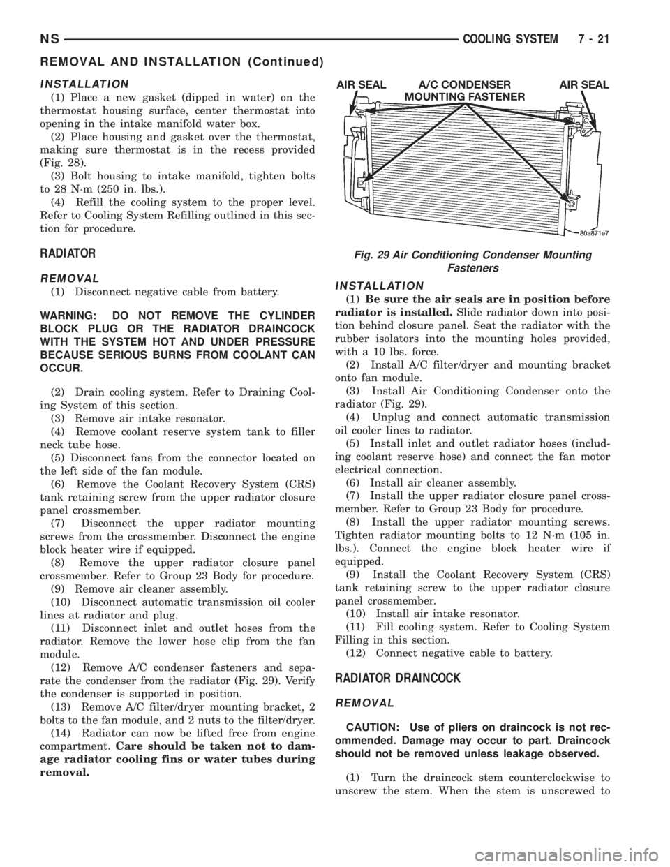
rate the condenser from the radiator (Fig. 29). Verify
the condenser is supported in position.
(13) Remove A/C filter/dryer mounting bracket, 2
bolts to the fan module, and 2 nuts to the filter/dryer.
(14) Radiator can now be lifted free from engine
compartment.Care should be taken not to dam-
age radiator cooling fins or water tubes during
removal.INSTALLATION
(1)Be sure the air seals are in position before
radiator is installed.Slide radiator down into posi-
tion behind closure panel. Seat the radiator with the
rubber isolators into the mounting holes provided,
with a 10 lbs. force.
(2) Install A/C filter/dryer and mounting bracket
onto fan module.
(3) Install Air Conditioning Condenser onto the
radiator (Fig. 29).
(4) Unplug and connect automatic transmission
oil cooler lines to radiator.
(5) Install inlet and outlet radiator hoses (includ-
ing coolant reserve hose) and connect the fan motor
electrical connection.
(6) Install air cleaner assembly.
(7) Install the upper radiator closure panel cross-
member. Refer to Group 23 Body for procedure.
(8) Install the upper radiator mounting screws.
Tighten radiator mounting bolts to 12 N´m (105 in.
lbs.). Connect the engine block heater wire if
equipped.
(9) Install the Coolant Recovery System (CRS)
tank retaining screw to the upper radiator closure
panel crossmember.
(10) Install air intake resonator.
(11) Fill cooling system. Refer to Cooling System
Filling in this section.
(12) Connect negative cable to battery.
RADIATOR DRAINCOCK
REMOVAL
CAUTION: Use of pliers on draincock is not rec-
ommended. Damage may occur to part. Draincock
should not be removed unless leakage observed.
(1) Turn the draincock stem counterclockwise to
unscrew the stem. When the stem is unscrewed to
Fig. 29 Air Conditioning Condenser Mounting
Fasteners
NSCOOLING SYSTEM 7 - 21
REMOVAL AND INSTALLATION (Continued)
Page 237 of 1938
(13) Raise the vehicle. Install the lower auxiliary
transmission cooler lines to the retaining clips on the
fan module shroud, if equipped.
(14) Install outlet hose retainer clip to the shroud.
Install the radiator outlet hose to the retaining clip.
(15) Lower the vehicle.
ENGINE BLOCK HEATER
REMOVAL
(1) Drain coolant from radiator and cylinder block.
Refer to Cooling System Drain, Clean, Flush and
Refill of this section for procedure.
(2) Remove power cord plug from heater.
(3) Loosen screw in center of heater. Remove
heater assembly.
INSTALLATION
(1) Thoroughly clean core hole and heater seat.
(2) Insert heater assembly with element loop posi-
tionedupward.
(3) With heater seated, tighten center screw
securely to assure a positive seal.
(4) Fill cooling system with coolant to the proper
level, vent air, and inspect for leaks. Pressurize sys-
tem with Radiator Pressure Tool before looking for
leaks.
(5) Install power cord plug to heater.
ACCESSORY DRIVE BELTSÐ2.4L
REMOVAL/INSTALLATION-ADJUST
GENERATOR AND AIR CONDITIONING
(1) Loosen lower generator pivot bolt and upper
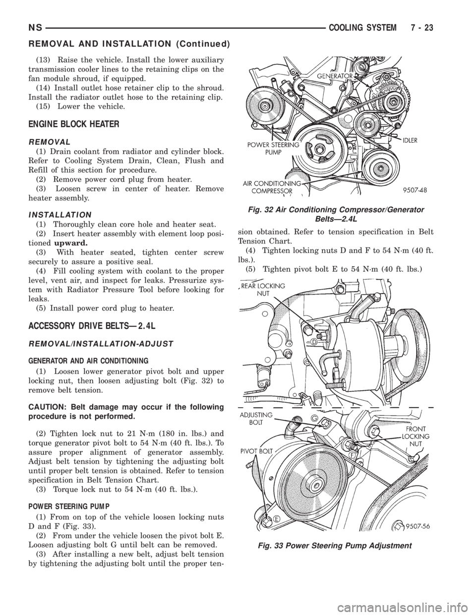
locking nut, then loosen adjusting bolt (Fig. 32) to
remove belt tension.
CAUTION: Belt damage may occur if the following
procedure is not performed.
(2) Tighten lock nut to 21 N´m (180 in. lbs.) and
torque generator pivot bolt to 54 N´m (40 ft. lbs.). To
assure proper alignment of generator assembly.
Adjust belt tension by tightening the adjusting bolt
until proper belt tension is obtained. Refer to tension
specification in Belt Tension Chart.
(3) Torque lock nut to 54 N´m (40 ft. lbs.).
POWER STEERING PUMP
(1) From on top of the vehicle loosen locking nuts
D and F (Fig. 33).
(2) From under the vehicle loosen the pivot bolt E.
Loosen adjusting bolt G until belt can be removed.
(3) After installing a new belt, adjust belt tension
by tightening the adjusting bolt until the proper ten-sion obtained. Refer to tension specification in Belt
Tension Chart.
(4) Tighten locking nuts D and F to 54 N´m (40 ft.
lbs.).
(5) Tighten pivot bolt E to 54 N´m (40 ft. lbs.)
Fig. 32 Air Conditioning Compressor/Generator
BeltsÐ2.4L
Fig. 33 Power Steering Pump Adjustment
NSCOOLING SYSTEM 7 - 23
REMOVAL AND INSTALLATION (Continued)
Page 240 of 1938
and the remove the splash shield to gain access to
the drive belts.
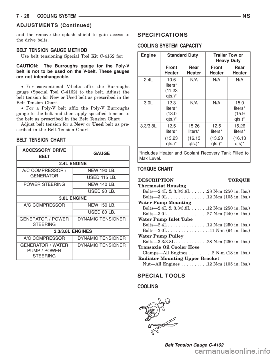
BELT TENSION GAUGE METHOD
Use belt tensioning Special Tool Kit C-4162 for:
CAUTION: The Burroughs gauge for the Poly-V
belt is not to be used on the V-belt. These gauges
are not interchangeable.
²For conventional V-belts affix the Burroughs
gauge (Special Tool C-4162) to the belt. Adjust the
belt tension for New or Used belt as prescribed in the
Belt Tension Chart.
²For a Poly-V belt affix the Poly-V Burroughs
gauge to the belt and then apply specified tension to
the belt as prescribed in the Belt Tension Chart
Adjust belt tension for aNeworUsedbelt as pre-
scribed in the Belt Tension Chart.
BELT TENSION CHARTSPECIFICATIONS
COOLING SYSTEM CAPACITY
TORQUE CHART
DESCRIPTION TORQUE
Thermostat Housing
BoltsÐ2.4L & 3.3/3.8L......28N´m(250 in. lbs.)
BoltsÐ3.0L...............12N´m(105 in. lbs.)
Water Pump Mounting
BoltsÐ2.4L & 3.3/3.8L......12N´m(250 in. lbs.)
BoltsÐ3.0L...............27N´m(240 in. lbs.)
Water Pump Inlet Tube
BoltsÐ2.4L...............12N´m(250 in. lbs.)
BoltsÐ3.0L................11N´m(94in.lbs.)
Water Pump Pulley
BoltsÐ3.3/3.8L............28N´m(250 in. lbs.)
Transaxle Oil Cooler Hose
ClampsÐAll Engines.........2N´m(18in.lbs.)
Radiator Mounting Upper Bracket
NutÐAll Engines..........12N´m(105 in. lbs.)
SPECIAL TOOLS
COOLING
ACCESSORY DRIVE
BELTGAUGE
2.4L ENGINE
A/C COMPRESSOR /
GENERATORNEW 190 LB.
USED 115 LB.
POWER STEERING NEW 140 LB.
USED 90 LB.
3.0L ENGINE
A/C COMPRESSOR NEW 150 LB.
USED 80 LB.
GENERATOR / POWER
STEERINGDYNAMIC TENSIONER
3.3/3.8L ENGINES
A/C COMPRESSOR DYNAMIC TENSIONER
GENERATOR / WATER
PUMP / POWER
STEERINGDYNAMIC TENSIONER
Engine Standard Duty Trailer Tow or
Heavy Duty
Front
HeaterRear
HeaterFront
HeaterRear
Heater
2.4L 10.6
liters*
(11.23
qts.)*N/A N/A N/A
3.0L 12.3
liters*
(13.0
qts.)*N/A N/A 15.0
liters*
(15.9
qts.)*
3.3/3.8L 12.5
liters*15.26
liters*12.5
liters*15.26
liters*
(13.23
qts.)*(16.13
qts.)*(13.23
qts.)*(16.13
qts)*
*Includes Heater and Coolant Recovery Tank Filled to
Max Level.
Belt Tension Gauge C-4162
7 - 26 COOLING SYSTEMNS
ADJUSTMENTS (Continued)
Page 241 of 1938

COOLING SYSTEM
CONTENTS
page page
GENERAL INFORMATION
COOLANT PRESSURE BOTTLE............ 1
COOLING SYSTEM Ð 2.0L GASOLINE...... 1
COOLING SYSTEM Ð 2.5L VM DIESEL..... 1
LOW COOLANT LEVEL SENSOR........... 1
RADIATOR............................ 2
DESCRIPTION AND OPERATION
AUTOMATIC BELT TENSIONER............ 6
BELT TENSION......................... 5
COOLANT PERFORMANCE............... 5
PRESSURE/VENT CAP................... 4
THERMOSTAT OPERATION............... 4
THERMOSTAT......................... 6
WATER PUMP......................... 3
SERVICE PROCEDURES
ADDING ADDITIONAL COOLANT........... 7
DRAINING COOLING SYSTEM............. 7
REFILLING COOLING SYSTEM............ 7
REMOVAL AND INSTALLATION
ENGINE THERMOSTATÐ 2.0L GASOLINE . . . 9GENERATOR/POWER STEERING BELT Ð 2.5L
VM DIESEL......................... 10
RADIATOR Ð 2.5L VM DIESEL........... 9
THERMOSTAT Ð 2.5L VM DIESEL......... 9
WATER PUMP BELT Ð 2.5L VM DIESEL . . . 10
WATER PUMP Ð 2.0L GASOLINE......... 7
WATER PUMP Ð 2.5L VM DIESEL........ 8
CLEANING AND INSPECTION
WATER PUMP........................ 10
ADJUSTMENTS
BELT TENSION CHART................. 11
BELT TENSION GAUGE METHOD......... 11
SPECIFICATIONS
COOLING SYSTEM CAPACITY............ 12
TORQUE CHART...................... 12
SPECIAL TOOLS
COOLING............................ 12
GENERAL INFORMATION
COOLING SYSTEM Ð 2.0L GASOLINE
The 2.0L gasoline engine cooling system consists of
an engine cooling module, thermostat, coolant, a
water pump to circulate the coolant. The engine cool-
ing module may consist of a radiator, electric fan
motors, fan, shroud, coolant reserve system, hoses,
clamps, air condition condenser.
²When the Engine is cold: The thermostat is
closed; the cooling system has no flow through the
radiator. The coolant flows through the engine,
heater system and bypass.
²When the Engine is warm: Thermostat is open;
the cooling system has flow through radiator, engine,
heater system and bypass.
COOLING SYSTEM Ð 2.5L VM DIESEL
The cooling system has a radiator, coolant, electric
fan motors, shroud, pressure cap, thermostat, coolant
pressure bottle, hoses, a water pump to circulate the
coolant, to complete the circuit. Coolant flow for the
VM diesel engine is shown in (Fig. 1).
COOLANT PRESSURE BOTTLE
2.5L VM DIESEL
This system works with the pressure cap to use
thermal expansion and contraction of the coolant to
keep the coolant free of trapped air. It provides some
reserve coolant to cover minor leaks and evaporation
or boiling losses. The coolant pressure bottle location
for 2.5L diesel is above the cylinder head cover (Fig.
2).
LOW COOLANT LEVEL SENSOR
The low coolant level sensor checks for low coolant
level in the coolant tank. A signal will be sent from
this sensor to the Body Control Module (BCM). When
the BCM determines low coolant level for 30 contin-
uous seconds, the instrument panel mounted low
coolant level warning lamp will be illuminated. The
sensor is located on the front side of the coolant tank
(Fig. 4). For information, refer to Group 8E, Instru-
ment Panel and Gauges.
If this lamp is illuminated, it indicates the need to
fill the coolant tank and check for leaks.
NS/GSCOOLING SYSTEM 7 - 1
Page 243 of 1938

ties to keep the engine satisfactorily cooled (Fig. 5)
and (Fig. 6).
CAUTION: Plastic tanks, while stronger then brass
are subject to damage by impact, such as wrenches
etc., or by excessive torque on hose clamps.
If the plastic tank is damaged, replace the radia-
tor.
DESCRIPTION AND OPERATION
WATER PUMP
2.0L GASOLINE
The water has a diecast aluminum body and hous-
ing with a stamped steel impeller. The water pumpbolts directly to the block (Fig. 7). Cylinder block to
water pump sealing is provided by a rubber O-ring.
The water pump is driven by the timing belt. Refer
to Group 9, Engine section for component removal to
access the water pump.
NOTE: The water pump on all models can be
replaced without discharging the air conditioning
system.
2.5L VM DIESEL
The Diesel engine water pump has an aluminum
body and housing with a stamped steel impeller. The
pump uses an O-ring gasket between body and hous-
ing. The water pump is driven by the accessory drive
belt, and the pump housing is bolted to the cylinder
block (Fig. 9).
NOTE: The water pump on all models can be
replaced without discharging the air conditioning
system.
Fig. 4 Low Coolant Level Sensor
Fig. 5 Cooling Module Ð2.0LGasoline
Fig. 6 Cooling Module ÐVM Diesel
NS/GSCOOLING SYSTEM 7 - 3
GENERAL INFORMATION (Continued)
Page 249 of 1938
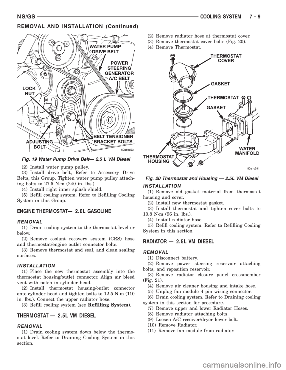
(2) Install water pump pulley.
(3) Install drive belt, Refer to Accessory Drive
Belts, this Group. Tighten water pump pulley attach-
ing bolts to 27.5 N´m (240 in. lbs.)
(4) Install right inner splash shield.
(5) Refill cooling system. Refer to Refilling Cooling
System in this Group.
ENGINE THERMOSTATÐ 2.0L GASOLINE
REMOVAL
(1) Drain cooling system to the thermostat level or
below.
(2) Remove coolant recovery system (CRS) hose
and thermostat/engine outlet connector bolts.
(3) Remove thermostat and seal, and clean sealing
surfaces.
INSTALLATION
(1) Place the new thermostat assembly into the
thermostat housing/outlet connector. Align air bleed
vent with notch in cylinder head.
(2) Install thermostat housing/outlet connector
onto cylinder head and tighten bolts to 12.5 N´m (110
in. lbs.). Connect the upper radiator hose.
(3) Refill cooling system (seeRefilling System).
THERMOSTAT Ð 2.5L VM DIESEL
REMOVAL
(1) Drain cooling system down below the thermo-
stat level. Refer to Draining Cooling System in this
section.(2) Remove radiator hose at thermostat cover.
(3) Remove thermostat cover bolts (Fig. 20).
(4) Remove Thermostat.
INSTALLATION
(1) Remove old gasket material from thermostat
housing and cover.
(2) Install new thermostat gasket.
(3) Install thermostat and tighten cover bolts to
10.8 N´m (96 in. lbs.).
(4) Install radiator hose.
(5) Refill cooling system. Refer to Refilling Cooling
System in this section.
RADIATOR Ð 2.5L VM DIESEL
REMOVAL
(1) Disconnect battery.
(2) Remove power steering reservoir attaching
bolts, and reposition reservoir.
(3) Remove radiator closure panel crossmember
(Fig. 21).
(4) Remove air cleaner housing and intake hose.
(5) Unplug fan module 4 pin wiring connector.
(6) Drain cooling system. Refer to Draining cooling
system in this section for procedure.
(7) Remove upper and lower Radiator Hoses.
(8) Remove radiator attaching bolts.
(9) Loosen A/C receiver/dryer lower bolt.
(10) Remove Radiator.
(11) Remove fan module from radiator.
Fig. 19 Water Pump Drive BeltÐ 2.5 L VM Diesel
Fig. 20 Thermostat and Housing Ð 2.5L VM Diesel
NS/GSCOOLING SYSTEM 7 - 9
REMOVAL AND INSTALLATION (Continued)
Page 304 of 1938

cylinder 4 crankshaft timing marks follow. One cam-
shaft pulse after the 3 pulses indicates cylinder 5.
The 2 camshaft pulses after cylinder 5 signals cylin-
der 6 (Fig. 10). The PCM can synchronize on cylin-
ders1or4.
When metal aligns with the sensor, voltage goes
low (less than 0.3 volts). When a notch aligns with
the sensor, voltage switches high (5.0 volts). As a
group of notches pass under the sensor, the voltage
switches from low (metal) to high (notch) then back
to low. The number of notches determine the amount
of pulses. If available, an oscilloscope can display the
square wave patterns of each timing event.
Top Dead Center (TDC) does not occur when
notches on the camshaft sprocket pass below the cyl-
inder. TDC occurs after the camshaft pulse (or
pulses) and after the 4 crankshaft pulses associated
with the particular cylinder. The arrows and cylinder
call outs on Figure 4 represent which cylinder the
flat spot and notches identify, they do not indicate
TDC position.
The camshaft position sensor is mounted in the
front of the timing case cover (Fig. 11).
MANIFOLD ABSOLUTE PRESSURE (MAP) SENSOR
The MAP sensor reacts to absolute pressure in the
intake manifold and provides an input voltage to the
Powertrain Control Module (PCM). As engine load
changes, manifold pressure varies. The changes in
engine load cause the MAP sensors resistance to
change. The change in MAP sensor resistance results
in a different input voltage to the PCM.
The input voltage level supplies the PCM with
information relating to ambient barometric pressure
during engine start-up (cranking) and engine load
while its operating. Based on MAP sensor voltage
and inputs from other sensors, the PCM adjusts
spark advance and the air-fuel mixture.
ENGINE COOLANT TEMPERATURE (ECT) SENSOR
The ECT sensor is located next to the thermostat
housing (Fig. 12). The sensor provides an input volt-
age to the Powertrain Control Module (PCM). Thesensor is a variable resistance (thermistor) with a
range of -40ÉF to 265ÉF. As coolant temperature var-
ies, the sensors resistance changes, resulting in a dif-
ferent input voltage to the PCM.
The PCM contains different spark advance sched-
ules for cold and warm engine operation. The sched-
ules reduce engine emission and improve driveability.
When the engine is cold, the PCM will demand
slightly richer air-fuel mixtures and higher idle
speeds until normal operating temperatures are
reached.
The ECT sensor input is also used for cooling fan
control.
Fig. 9 Camshaft Position Sensor
Fig. 10 Camshaft Sprocket
Fig. 11 Camshaft Position Sensor Location
8D - 6 IGNITION SYSTEMNS
GENERAL INFORMATION (Continued)
Page 319 of 1938

REMOVAL
(1) With the engine cold, drain coolant until level
drops below cylinder head. Refer to Group 7, Cooling
System.
(2) Disconnect coolant sensor electrical connector.
(3) Remove coolant sensor.
INSTALLATION
(1) Install coolant sensor. Tighten sensor to 7 N´m
(60 in. lbs.) torque.
(2) Attach electrical connector to sensor.
(3) Fill cooling system. Refer to Group 7, Cooling
System.
KNOCK SENSORÐ2.4L
The knock sensor threads into the side of the cyl-
inder block in front of the starter (Fig. 14).
REMOVAL
(1) Disconnect electrical connector from knock sen-
sor.
(2) Use a crow foot socket to remove the knock
sensors.
INSTALLATION
(1) Install knock sensor. Tighten knock sensor to
10 N´m (7 ft. lbs.) torque.Over or under tighten-
ing effects knock sensor performance, possibly
causing improper spark control.
(2) Attach electrical connector to knock sensor.
INTAKE AIR TEMPERATURE SENSORÐ2.4L
The intake air temperature sensor threads into the
intake manifold plenum (Fig. 15).
REMOVAL
(1) Remove electrical connector from sensor.
(2) Remove sensor.
INSTALLATION
(1) Install sensor. Tighten sensor to 28 N´m (20 ft.
lbs.) torque.
(2) Attach electrical connector to sensor.
Fig. 14 Knock Sensor
Fig. 15 Intake Air Temperature Sensor
NSIGNITION SYSTEM 8D - 21
REMOVAL AND INSTALLATION (Continued)