check engine CHRYSLER VOYAGER 1996 Owner's Guide
[x] Cancel search | Manufacturer: CHRYSLER, Model Year: 1996, Model line: VOYAGER, Model: CHRYSLER VOYAGER 1996Pages: 1938, PDF Size: 55.84 MB
Page 230 of 1938

at running operating temperature the high pressure
inlet tank runs full and the low pressure outlet tank
drops:
²Transmission oil will become hotter.
²High reading shown on the temperature gauge.
²Air in the coolant can cause loss of flow through
the heater.
²Exhaust gas leaks into the coolant also can
cause the same problems.
DEAERATION
Air can only be removed from the system by gath-
ering under the pressure cap. On the next heat up it
will be pushed past the pressure cap into the CRS
tank by thermal expansion of the coolant. It then
escapes to the atmosphere in the CRS tank and is
replaced with solid coolant on cool down.
TEMPERATURE GAUGE INDICATION
At idle with Air Conditioning off the temperature
gauge will rise slowly to about 5/8 gauge travel, the
fan will come on and the gauge will quickly drop to
about 1/2 gauge travel. This is normal.
SERVICE PROCEDURES
COOLANT LEVEL CHECKÐROUTINE
Do not remove radiator cap for routine cool-
ant level inspections.
The coolant reserve system provides a quick visual
method for determining the coolant level without
removing the radiator cap.With the engine cold
and not running,simply observe the level of the
coolant in the reserve tank (Fig. 3). The coolant level
should be between the minimum and maximum
marks.
COOLANTÐADDING ADDITIONAL
The radiator cap should not be removed.
When additional coolant is needed to maintain this
level, it should be added to the coolant reserve tank.
Use only 50/50 mix of ethylene glycol type antifreeze
and water.
CAUTION: Do not use well water, or suspect water
supply in cooling system. A 50/50 ethylene glycol
and distilled water mix is recommended.
COOLANT LEVEL SERVICE
The cooling system is closed and designed to main-
tain coolant level to the top of the radiator.
When servicing requires a coolant level check in
the radiator, the engine must beoffandnotunder
pressure. Drain several ounces of coolant from the
radiator draincock while observing the CoolantRecovery System (CRS) Tank. Coolant level in the
CRS tank should drop slightly. Then remove the radi-
ator cap. The radiator should be full to the top. If
not, and the coolant level in the CRS tank is at the
MIN mark there is an air leak in the CRS system.
Check hose or hose connections to the CRS tank,
radiator filler neck or the pressure cap seal to the
radiator filler neck for leaks.
COOLING SYSTEMÐDRAINING
Without removing radiator pressure cap and
with system not under pressure,shut engine off
and open draincock. The coolant reserve tank should
empty first, then remove radiator pressure cap. (if
not, see Testing Cooling System for leaks). To vent
2.4L engine remove the coolant temperature sensor
located above water outlet housing (Fig. 15). The 3.0/
3.3/3.8L engines have an air bleed vent on the ther-
mostat.
Removal of a sensor is required because the ther-
mostat does not have an air vent. Sensor removal
allows an air bleed for coolant to drain from the
engine block.
COOLING SYSTEMÐREFILLING
First clean system to remove old coolant, see Cool-
ing System Cleaning.
Fill the system, using the correct antifreeze as
described in the Coolant Section. Fill the system to
50 percent of its capacity with 100 percent glycol.
Then complete filling system with water. The 2.4L
engine requires venting by removal of the coolant
sensor on top of the water outlet connector (Fig. 15).
When coolant reaches this hole:
²Install coolant sensor and tighten to 7 N´m (60
in. lbs.) for 2.4L Engines.
Fig. 15 Coolant Temperature SensorÐ2.4L Engine
Drain/Fill
7 - 16 COOLING SYSTEMNS
DIAGNOSIS AND TESTING (Continued)
Page 231 of 1938
Continue filling system until full, this provides bet-
ter heater performance.Be careful not to spill
coolant on drive belts or the generator.
Fill coolant reserve system to at least the MAX
mark with 50/50 solution. It may be necessary to add
coolant to the reserve tank after three or four warm
up/cool down cycles to maintain coolant level between
the MAX and MIN mark. This will allow trapped air
to be removed from the system.
REMOVAL AND INSTALLATION
WATER PUMPÐ2.4L ENGINE
REMOVAL
(1) Disconnect negative cable from battery.
(2) Raise vehicle on a hoist. Remove right inner
splash shield.
(3) Remove accessory drive belts. Refer to Acces-
sory Drive Belt service in this section.
(4) Drain cooling system. Refer to Cooling System
Draining in this section.
(5) Support engine from the bottom and remove
right engine mount.
(6) Remove right engine mount bracket.
(7) Remove timing belt. Refer to Group 9, Engine
for procedure.
(8) Remove timing belt idler pulley.
(9) Hold camshaft sprocket with Special tool
C-4687 and adaptor C-4687-1 while removing bolt.
Remove both cam sprockets.
(10) Remove rear timing belt cover.
(11) Remove water pump attaching screws to
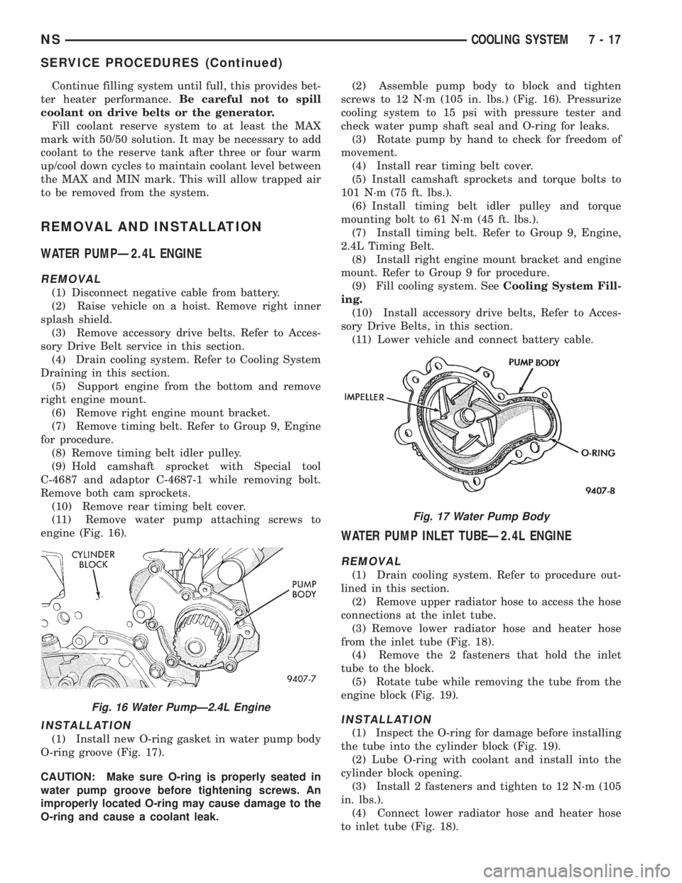
engine (Fig. 16).
INSTALLATION
(1) Install new O-ring gasket in water pump body
O-ring groove (Fig. 17).
CAUTION: Make sure O-ring is properly seated in
water pump groove before tightening screws. An
improperly located O-ring may cause damage to the
O-ring and cause a coolant leak.(2) Assemble pump body to block and tighten
screws to 12 N´m (105 in. lbs.) (Fig. 16). Pressurize
cooling system to 15 psi with pressure tester and
check water pump shaft seal and O-ring for leaks.
(3) Rotate pump by hand to check for freedom of
movement.
(4) Install rear timing belt cover.
(5) Install camshaft sprockets and torque bolts to
101 N´m (75 ft. lbs.).
(6) Install timing belt idler pulley and torque
mounting bolt to 61 N´m (45 ft. lbs.).
(7) Install timing belt. Refer to Group 9, Engine,
2.4L Timing Belt.
(8) Install right engine mount bracket and engine
mount. Refer to Group 9 for procedure.
(9) Fill cooling system. SeeCooling System Fill-
ing.
(10) Install accessory drive belts, Refer to Acces-
sory Drive Belts, in this section.
(11) Lower vehicle and connect battery cable.
WATER PUMP INLET TUBEÐ2.4L ENGINE
REMOVAL
(1) Drain cooling system. Refer to procedure out-
lined in this section.
(2) Remove upper radiator hose to access the hose
connections at the inlet tube.
(3) Remove lower radiator hose and heater hose
from the inlet tube (Fig. 18).
(4) Remove the 2 fasteners that hold the inlet
tube to the block.
(5) Rotate tube while removing the tube from the
engine block (Fig. 19).
INSTALLATION
(1) Inspect the O-ring for damage before installing
the tube into the cylinder block (Fig. 19).
(2) Lube O-ring with coolant and install into the
cylinder block opening.
(3) Install 2 fasteners and tighten to 12 N´m (105
in. lbs.).
(4) Connect lower radiator hose and heater hose
to inlet tube (Fig. 18).
Fig. 16 Water PumpÐ2.4L Engine
Fig. 17 Water Pump Body
NSCOOLING SYSTEM 7 - 17
SERVICE PROCEDURES (Continued)
Page 233 of 1938
INSTALLATION
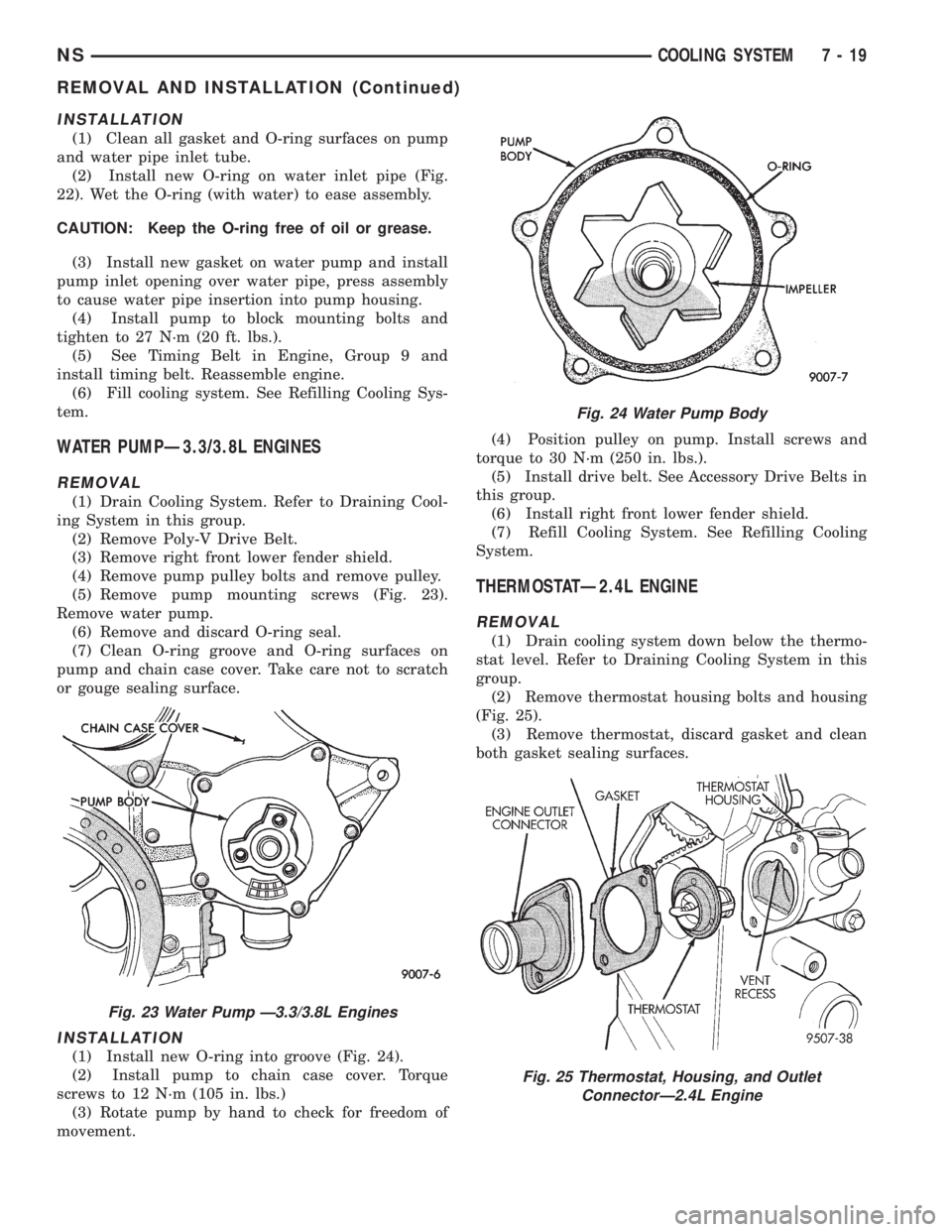
(1) Clean all gasket and O-ring surfaces on pump
and water pipe inlet tube.
(2) Install new O-ring on water inlet pipe (Fig.
22). Wet the O-ring (with water) to ease assembly.
CAUTION: Keep the O-ring free of oil or grease.
(3) Install new gasket on water pump and install
pump inlet opening over water pipe, press assembly
to cause water pipe insertion into pump housing.
(4) Install pump to block mounting bolts and
tighten to 27 N´m (20 ft. lbs.).
(5) See Timing Belt in Engine, Group 9 and
install timing belt. Reassemble engine.
(6) Fill cooling system. See Refilling Cooling Sys-
tem.
WATER PUMPÐ3.3/3.8L ENGINES
REMOVAL
(1) Drain Cooling System. Refer to Draining Cool-
ing System in this group.
(2) Remove Poly-V Drive Belt.
(3) Remove right front lower fender shield.
(4) Remove pump pulley bolts and remove pulley.
(5) Remove pump mounting screws (Fig. 23).
Remove water pump.
(6) Remove and discard O-ring seal.
(7) Clean O-ring groove and O-ring surfaces on
pump and chain case cover. Take care not to scratch
or gouge sealing surface.
INSTALLATION
(1) Install new O-ring into groove (Fig. 24).
(2) Install pump to chain case cover. Torque
screws to 12 N´m (105 in. lbs.)
(3) Rotate pump by hand to check for freedom of
movement.(4) Position pulley on pump. Install screws and
torque to 30 N´m (250 in. lbs.).
(5) Install drive belt. See Accessory Drive Belts in
this group.
(6) Install right front lower fender shield.
(7) Refill Cooling System. See Refilling Cooling
System.
THERMOSTATÐ2.4L ENGINE
REMOVAL
(1) Drain cooling system down below the thermo-
stat level. Refer to Draining Cooling System in this
group.
(2) Remove thermostat housing bolts and housing
(Fig. 25).
(3) Remove thermostat, discard gasket and clean
both gasket sealing surfaces.
Fig. 23 Water Pump Ð3.3/3.8L Engines
Fig. 24 Water Pump Body
Fig. 25 Thermostat, Housing, and Outlet
ConnectorÐ2.4L Engine
NSCOOLING SYSTEM 7 - 19
REMOVAL AND INSTALLATION (Continued)
Page 234 of 1938
INSTALLATIONÐ2.4L ENGINE
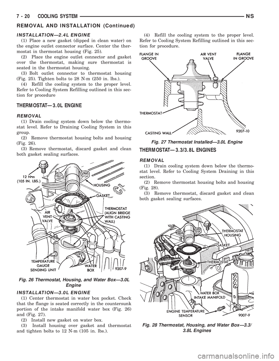
(1) Place a new gasket (dipped in clean water) on
the engine outlet connector surface. Center the ther-
mostat in thermostat housing (Fig. 25).
(2) Place the engine outlet connector and gasket
over the thermostat, making sure thermostat is
seated in the thermostat housing.
(3) Bolt outlet connector to thermostat housing
(Fig. 25). Tighten bolts to 28 N´m (250 in. lbs.).
(4) Refill the cooling system to the proper level.
Refer to Cooling System Refilling outlined in this sec-
tion for procedure
THERMOSTATÐ3.0L ENGINE
REMOVAL
(1) Drain cooling system down below the thermo-
stat level. Refer to Draining Cooling System in this
group.
(2) Remove thermostat housing bolts and housing
(Fig. 26).
(3) Remove thermostat, discard gasket and clean
both gasket sealing surfaces.
INSTALLATIONÐ3.0L ENGINE
(1) Center thermostat in water box pocket. Check
that the flange is seated correctly in the countersunk
portion of the intake manifold water box (Fig. 26)
and (Fig. 27).
(2) Install new gasket on water box.
(3) Install housing over gasket and thermostat
and tighten bolts to 12 N´m (105 in. lbs.).(4) Refill the cooling system to the proper level.
Refer to Cooling System Refilling outlined in this sec-
tion for procedure.
THERMOSTATÐ3.3/3.8L ENGINES
REMOVAL
(1) Drain cooling system down below the thermo-
stat level. Refer to Cooling System Draining in this
section.
(2) Remove thermostat housing bolts and housing
(Fig. 28).
(3) Remove thermostat, discard gasket and clean
both gasket sealing surfaces.
Fig. 26 Thermostat, Housing, and Water BoxÐ3.0L
Engine
Fig. 27 Thermostat InstalledÐ3.0L Engine
Fig. 28 Thermostat, Housing, and Water BoxÐ3.3/
3.8L Engines
7 - 20 COOLING SYSTEMNS
REMOVAL AND INSTALLATION (Continued)
Page 241 of 1938

COOLING SYSTEM
CONTENTS
page page
GENERAL INFORMATION
COOLANT PRESSURE BOTTLE............ 1
COOLING SYSTEM Ð 2.0L GASOLINE...... 1
COOLING SYSTEM Ð 2.5L VM DIESEL..... 1
LOW COOLANT LEVEL SENSOR........... 1
RADIATOR............................ 2
DESCRIPTION AND OPERATION
AUTOMATIC BELT TENSIONER............ 6
BELT TENSION......................... 5
COOLANT PERFORMANCE............... 5
PRESSURE/VENT CAP................... 4
THERMOSTAT OPERATION............... 4
THERMOSTAT......................... 6
WATER PUMP......................... 3
SERVICE PROCEDURES
ADDING ADDITIONAL COOLANT........... 7
DRAINING COOLING SYSTEM............. 7
REFILLING COOLING SYSTEM............ 7
REMOVAL AND INSTALLATION
ENGINE THERMOSTATÐ 2.0L GASOLINE . . . 9GENERATOR/POWER STEERING BELT Ð 2.5L
VM DIESEL......................... 10
RADIATOR Ð 2.5L VM DIESEL........... 9
THERMOSTAT Ð 2.5L VM DIESEL......... 9
WATER PUMP BELT Ð 2.5L VM DIESEL . . . 10
WATER PUMP Ð 2.0L GASOLINE......... 7
WATER PUMP Ð 2.5L VM DIESEL........ 8
CLEANING AND INSPECTION
WATER PUMP........................ 10
ADJUSTMENTS
BELT TENSION CHART................. 11
BELT TENSION GAUGE METHOD......... 11
SPECIFICATIONS
COOLING SYSTEM CAPACITY............ 12
TORQUE CHART...................... 12
SPECIAL TOOLS
COOLING............................ 12
GENERAL INFORMATION
COOLING SYSTEM Ð 2.0L GASOLINE
The 2.0L gasoline engine cooling system consists of
an engine cooling module, thermostat, coolant, a
water pump to circulate the coolant. The engine cool-
ing module may consist of a radiator, electric fan
motors, fan, shroud, coolant reserve system, hoses,
clamps, air condition condenser.
²When the Engine is cold: The thermostat is
closed; the cooling system has no flow through the
radiator. The coolant flows through the engine,
heater system and bypass.
²When the Engine is warm: Thermostat is open;
the cooling system has flow through radiator, engine,
heater system and bypass.
COOLING SYSTEM Ð 2.5L VM DIESEL
The cooling system has a radiator, coolant, electric
fan motors, shroud, pressure cap, thermostat, coolant
pressure bottle, hoses, a water pump to circulate the
coolant, to complete the circuit. Coolant flow for the
VM diesel engine is shown in (Fig. 1).
COOLANT PRESSURE BOTTLE
2.5L VM DIESEL
This system works with the pressure cap to use
thermal expansion and contraction of the coolant to
keep the coolant free of trapped air. It provides some
reserve coolant to cover minor leaks and evaporation
or boiling losses. The coolant pressure bottle location
for 2.5L diesel is above the cylinder head cover (Fig.
2).
LOW COOLANT LEVEL SENSOR
The low coolant level sensor checks for low coolant
level in the coolant tank. A signal will be sent from
this sensor to the Body Control Module (BCM). When
the BCM determines low coolant level for 30 contin-
uous seconds, the instrument panel mounted low
coolant level warning lamp will be illuminated. The
sensor is located on the front side of the coolant tank
(Fig. 4). For information, refer to Group 8E, Instru-
ment Panel and Gauges.
If this lamp is illuminated, it indicates the need to
fill the coolant tank and check for leaks.
NS/GSCOOLING SYSTEM 7 - 1
Page 246 of 1938
Initial belt adjustment is done with a adjustable
tensioner pulley. After the initial adjustment is per-
formed, an automatic belt tensioner is used to main-
tain correct belt tension at all times. Do not attempt
to check belt tension with a belt tension gauge on
vehicles equipped with an automatic belt tensioner.
Refer to Automatic Belt Tensioner in this group.
AUTOMATIC BELT TENSIONER
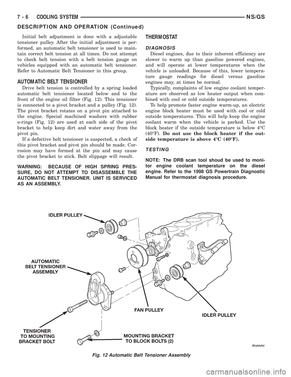
Drive belt tension is controlled by a spring loaded
automatic belt tensioner located below and to the
front of the engine oil filter (Fig. 12). This tensioner
is connected to a pivot bracket and a pulley (Fig. 12).
The pivot bracket rotates on a pivot pin attached to
the engine. Special machined washers with rubber
o-rings (Fig. 12) are used at each side of the pivot
bracket to help keep dirt and water away from the
pivot pin.
If a defective belt tensioner is suspected, a check of
this pivot bracket and pivot pin should be made. Cor-
rosion may have formed at the pin and may cause
the pivot bracket to stick. Belt slippage will result.
WARNING: BECAUSE OF HIGH SPRING PRES-
SURE, DO NOT ATTEMPT TO DISASSEMBLE THE
AUTOMATIC BELT TENSIONER. UNIT IS SERVICED
AS AN ASSEMBLY.
THERMOSTAT
DIAGNOSIS
Diesel engines, due to their inherent efficiency are
slower to warm up than gasoline powered engines,
and will operate at lower temperatures when the
vehicle is unloaded. Because of this, lower tempera-
ture gauge readings for diesel versus gasoline
engines may, at times be normal.
Typically, complaints of low engine coolant temper-
ature are observed as low heater output when com-
bined with cool or cold outside temperatures.
To help promote faster engine warm-up, an electric
engine block heater must be used with cool or cold
outside temperatures. This will help keep the engine
coolant warm when the vehicle is parked. Use the
block heater if the outside temperature is below 4ÉC
(40ÉF).Do not use the block heater if the out-
side temperature is above 4ÉC (40ÉF).
TESTING
NOTE: The DRB scan tool shoud be used to moni-
tor engine coolant temperature on the diesel
engine. Refer to the 1998 GS Powertrain Diagnostic
Manual for thermostat diagnosis procedure.
Fig. 12 Automatic Belt Tensioner Assembly
7 - 6 COOLING SYSTEMNS/GS
DESCRIPTION AND OPERATION (Continued)
Page 248 of 1938
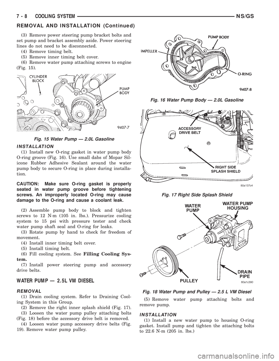
(3) Remove power steering pump bracket bolts and
set pump and bracket assembly aside. Power steering
lines do not need to be disconnected.
(4) Remove timing belt.
(5) Remove inner timing belt cover.
(6) Remove water pump attaching screws to engine
(Fig. 15).
INSTALLATION
(1) Install new O-ring gasket in water pump body
O-ring groove (Fig. 16). Use small dabs of Mopar Sil-
icone Rubber Adhesive Sealant around the water
pump body to secure O-ring in place during installa-
tion.
CAUTION: Make sure O-ring gasket is properly
seated in water pump groove before tightening
screws. An improperly located O-ring may cause
damage to the O-ring and cause a coolant leak.
(2) Assemble pump body to block and tighten
screws to 12 N´m (105 in. lbs.). Pressurize cooling
system to 15 psi with pressure tester and check
water pump shaft seal and O-ring for leaks.
(3) Rotate pump by hand to check for freedom of
movement.
(4) Install inner timing belt cover.
(5) Install timing belt.
(6) Fill cooling system. SeeFilling Cooling Sys-
tem.
(7) Install power steering pump and accessory
drive belts.
WATER PUMP Ð 2.5L VM DIESEL
REMOVAL
(1) Drain cooling system. Refer to Draining Cool-
ing System in this Group.
(2) Remove the right inner splash shield (Fig. 17).
(3) Loosen the water pump pulley attaching bolts
(Fig. 18) before the accessory drive belt is removed.
(4) Loosen water pump accessory drive belts (Fig.
19). Remove water pump pulley.(5) Remove water pump attaching bolts and
remove pump.
INSTALLATION
(1) Install a new water pump to housing O-ring
gasket. Install pump and tighten the attaching bolts
to 22.6 N´m (205 in. lbs.)
Fig. 15 Water Pump Ð 2.0L Gasoline
Fig. 16 Water Pump Body Ð 2.0L Gasoline
Fig. 17 Right Side Splash Shield
Fig. 18 Water Pump and Pulley Ð 2.5 L VM Diesel
7 - 8 COOLING SYSTEMNS/GS
REMOVAL AND INSTALLATION (Continued)
Page 255 of 1938

use. Refer to Causes of Battery Discharging in this
Group for more information.
NOTE: CLEAR COLOR = Replace Battery
WARNING: DO NOT CHARGE, ASSIST BOOST,
LOAD TEST, OR ADD WATER TO THE BATTERY
WHEN CLEAR COLOR DOT IS VISIBLE. PERSONAL
INJURY MAY OCCUR.
A clear color dot shows electrolyte level in battery
is below the test indicator (Fig. 1). Water cannot be
added to a maintenance free battery. The battery
must be replaced. A low electrolyte level may be
caused by an over charging condition. Refer to Gen-
erator Test Procedures on Vehicle.
CAUSES OF BATTERY DISCHARGING
It is normal to have a small 5 to 25 milliamperes
continuous electrical draw from the battery. This
draw will take place with the ignition in the OFF
position, and the courtesy, dome, storage compart-
ments, and engine compartment lights OFF. The con-
tinuous draw is due to various electronic features or
accessories that require electrical current with the
ignition OFF to function properly. When a vehicle is
not used over an extended period of approximately 20
days the IOD fuse should be pulled. The fuse is
located in the power distribution center. Disconnec-
tion of this fuse will reduce the level of battery dis-
charge. Refer to Battery Diagnosis and Testing table
and to the proper procedures.
ABNORMAL BATTERY DISCHARGING
²Corroded battery posts, cables or terminals.
²Loose or worn generator drive belt.
²Electrical loads that exceed the output of the
charging system due to equipment or accessories
installed after delivery.
²Slow driving speeds in heavy traffic conditions
or prolonged idling with high-amperage electrical
systems in use.²Defective electrical circuit or component causing
excess Ignition Off Draw (IOD). Refer to Battery
Ignition Off Draw (IOD).
²Defective charging system.
²Defective battery.
BATTERY IGNITION OFF DRAW (IOD)
High current draw on the battery with the ignition
OFF will discharge a battery. After a dead battery is
serviced the vehicle Ignition Off Draw (IOD) should
be checked. Determine if a high current draw condi-
tion exists first check the vehicle with a test lamp.
(1) Verify that all electrical accessories are OFF.
²Remove key from ignition switch
²Turn off all lights
²Liftgate and glove box door is closed
²Sun visor vanity lights are OFF
²All doors are closed
²Allow the Illuminated Entry System to time out
in approximately 30 seconds, if equipped.
²During Transmission Control Module (TCM)
power down there will be 500 milliamperes present
for 20 minutes. Afterwards less than 1.0 milliampere.
(2) Disconnect battery negative cable (Fig. 4).
CAUTION: Always disconnect the meter before
opening a door.
(3) Using an multimeter, that has least a milliam-
pere range of 200 mA. Set meter to the highest mA
range. Install meter between the battery negative
cable and battery negative post (Fig. 5). Carefully
remove the test lamp without disconnecting the
meter. After all modules time-out the total vehicle
IOD should be less than 25 milliamperes. If ignition
off draw is more than 25 milliamperes go to Step 4.
(4) Each time the test lamp or milliampere meter
is disconnected and connected, all electronic timer
functions will be activated for approximately one
minute. The Body Control Module (BCM) ignition off
draw can reach 90 milliamperes.
(5) Remove the PDC fuses:
²Interior lamps
²Brake lamp
²IOD
(6) If there is any reading, with fuses removed
there is a short circuit in the wiring. Refer to Group
8W, wiring diagrams. If reading is less than 25 mA
go to Step 8.
(7) Install all fuses. After installing fuse, the cur-
rent can reach 90 mA. After time-out the reading
should not exceed 25 mA. If OK go to. If not, discon-
nect:
²Radio
²Body Control Module
²Remote Keyless Entry Module
Fig. 3 Test Indicator
NSBATTERY 8A - 3
DIAGNOSIS AND TESTING (Continued)
Page 256 of 1938
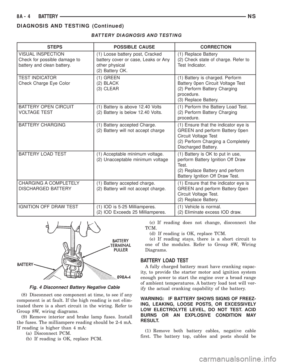
(8) Disconnect one component at time, to see if any
component is at fault. If the high reading is not elim-
inated there is a short circuit in the wiring. Refer to
Group 8W, wiring diagrams.
(9) Remove interior and brake lamp fuses. Install
the fuses. The milliampere reading should be 2-4 mA.
If reading is higher than 4 mA:
(a) Disconnect PCM.
(b) If reading is OK, replace PCM.(c) If reading does not change, disconnect the
TCM.
(d) If reading is OK, replace TCM.
(e) If reading stays, there is a short circuit to
one of the modules. Refer to Group 8W, Wiring
Diagrams.
BATTERY LOAD TEST
A fully charged battery must have cranking capac-
ity, to provide the starter motor and ignition system
enough power to start the engine over a broad range
of ambient temperatures. A battery load test will ver-
ify the actual cranking capability of the battery.
WARNING: IF BATTERY SHOWS SIGNS OF FREEZ-
ING, LEAKING, LOOSE POSTS, OR EXCESSIVELY
LOW ELECTROLYTE LEVEL, DO NOT TEST. ACID
BURNS OR AN EXPLOSIVE CONDITION MAY
RESULT.
(1) Remove both battery cables, negative cable
first. The battery top, cables and posts should be
BATTERY DIAGNOSIS AND TESTING
STEPS POSSIBLE CAUSE CORRECTION
VISUAL INSPECTION
Check for possible damage to
battery and clean battery.(1) Loose battery post, Cracked
battery cover or case, Leaks or Any
other physical
(2) Battery OK.(1) Replace Battery
(2) Check state of charge. Refer to
Test Indicator.
TEST INDICATOR
Check Charge Eye Color(1) GREEN
(2) BLACK
(3) CLEAR(1) Battery is charged. Perform
Battery 0pen Circuit Voltage Test
(2) Perform Battery Charging
procedure.
(3) Replace Battery.
BATTERY OPEN CIRCUIT
VOLTAGE TEST(1) Battery is above 12.40 Volts
(2) Battery is below 12.40 Volts.(1) Perform the Battery Load Test.
(2) Perform Battery Charging
procedure.
BATTERY CHARGING (1) Battery accepted Charge.
(2) Battery will not accept charge(1) Ensure that the indicator eye is
GREEN and perform Battery 0pen
Circuit Voltage Test
(2) Perform Charging a Completely
Discharged Battery.
BATTERY LOAD TEST (1) Acceptable minimum voltage.
(2) Unacceptable minimum voltage(1) Battery is OK to put in use,
perform Battery Ignition Off Draw
Test.
(2) Replace Battery and perform
Battery Ignition Off Draw Test.
CHARGING A COMPLETELY
DISCHARGED BATTERY(1) Battery accepted charge.
(2) Battery will not accept charge.(1) Ensure that the indicator eye is
GREEN and perform Battery 0pen
Circuit Voltage Test.
(2) Replace Battery.
IGNITION OFF DRAW TEST (1) IOD is 5-25 Milliamperes.
(2) IOD Exceeds 25 Milliamperes.(1) Vehicle is normal.
(2) Eliminate excess IOD draw.
Fig. 4 Disconnect Battery Negative Cable
8A - 4 BATTERYNS
DIAGNOSIS AND TESTING (Continued)
Page 265 of 1938
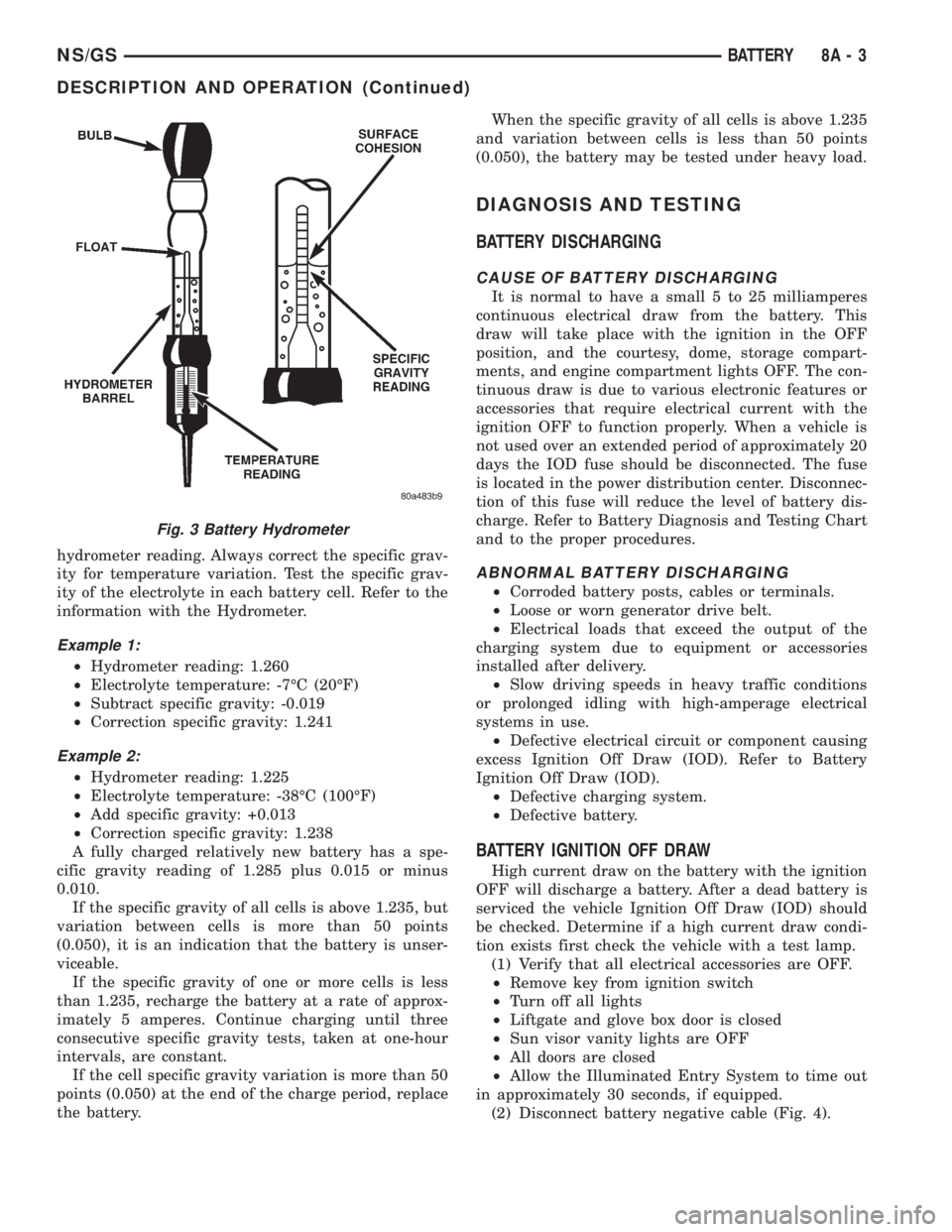
hydrometer reading. Always correct the specific grav-
ity for temperature variation. Test the specific grav-
ity of the electrolyte in each battery cell. Refer to the
information with the Hydrometer.
Example 1:
²Hydrometer reading: 1.260
²Electrolyte temperature: -7ÉC (20ÉF)
²Subtract specific gravity: -0.019
²Correction specific gravity: 1.241
Example 2:
²Hydrometer reading: 1.225
²Electrolyte temperature: -38ÉC (100ÉF)
²Add specific gravity: +0.013
²Correction specific gravity: 1.238
A fully charged relatively new battery has a spe-
cific gravity reading of 1.285 plus 0.015 or minus
0.010.
If the specific gravity of all cells is above 1.235, but
variation between cells is more than 50 points
(0.050), it is an indication that the battery is unser-
viceable.
If the specific gravity of one or more cells is less
than 1.235, recharge the battery at a rate of approx-
imately 5 amperes. Continue charging until three
consecutive specific gravity tests, taken at one-hour
intervals, are constant.
If the cell specific gravity variation is more than 50
points (0.050) at the end of the charge period, replace
the battery.When the specific gravity of all cells is above 1.235
and variation between cells is less than 50 points
(0.050), the battery may be tested under heavy load.
DIAGNOSIS AND TESTING
BATTERY DISCHARGING
CAUSE OF BATTERY DISCHARGING
It is normal to have a small 5 to 25 milliamperes
continuous electrical draw from the battery. This
draw will take place with the ignition in the OFF
position, and the courtesy, dome, storage compart-
ments, and engine compartment lights OFF. The con-
tinuous draw is due to various electronic features or
accessories that require electrical current with the
ignition OFF to function properly. When a vehicle is
not used over an extended period of approximately 20
days the IOD fuse should be disconnected. The fuse
is located in the power distribution center. Disconnec-
tion of this fuse will reduce the level of battery dis-
charge. Refer to Battery Diagnosis and Testing Chart
and to the proper procedures.
ABNORMAL BATTERY DISCHARGING
²Corroded battery posts, cables or terminals.
²Loose or worn generator drive belt.
²Electrical loads that exceed the output of the
charging system due to equipment or accessories
installed after delivery.
²Slow driving speeds in heavy traffic conditions
or prolonged idling with high-amperage electrical
systems in use.
²Defective electrical circuit or component causing
excess Ignition Off Draw (IOD). Refer to Battery
Ignition Off Draw (IOD).
²Defective charging system.
²Defective battery.
BATTERY IGNITION OFF DRAW
High current draw on the battery with the ignition
OFF will discharge a battery. After a dead battery is
serviced the vehicle Ignition Off Draw (IOD) should
be checked. Determine if a high current draw condi-
tion exists first check the vehicle with a test lamp.
(1) Verify that all electrical accessories are OFF.
²Remove key from ignition switch
²Turn off all lights
²Liftgate and glove box door is closed
²Sun visor vanity lights are OFF
²All doors are closed
²Allow the Illuminated Entry System to time out
in approximately 30 seconds, if equipped.
(2) Disconnect battery negative cable (Fig. 4).
Fig. 3 Battery Hydrometer
NS/GSBATTERY 8A - 3
DESCRIPTION AND OPERATION (Continued)