ECU CHRYSLER VOYAGER 1996 Manual PDF
[x] Cancel search | Manufacturer: CHRYSLER, Model Year: 1996, Model line: VOYAGER, Model: CHRYSLER VOYAGER 1996Pages: 1938, PDF Size: 55.84 MB
Page 1306 of 1938
(9) Momentarily touch the other end of this
jumper wire to the negative terminal of the battery
for no more than 4 seconds.
(10) Place a rag or towel below the fuel line at the
quick connect to the rail.
(11) Disconnect the quick connect fitting to the
rail. Refer to Quick-Connect Fittings in this section.
(12) Return the fuel pump relay to the PDC.
(13) One or more Diagnostic Trouble Codes (DTC's)
may have been stored in the PCM memory due to the
fuel pump relay removal. The DRB scan tool must be
used to erase a DTC. Refer to group 25, On-Board
Diagnostics.
HOSES AND CLAMPS
Inspect all hose connections (clamps and quick con-
nect fittings) for completeness and leaks. Replace
cracked, scuffed, or swelled hoses. Replace hoses that
rub against other vehicle components or show sign of
wear.
Fuel injected vehicles use specially constructed
hoses. When replacing hoses, only use hoses marked
EFM/EFI.
When installing hoses, ensure that they are routed
away from contact with other vehicle components
that could rub against them and cause failure. Avoid
contact with clamps or other components that cause
abrasions or scuffing. Ensure that rubber hoses are
properly routed and avoid heat sources.
The hose clamps have rolled edges to prevent the
clamp from cutting into the hose. Only use clamps
that are original equipment or equivalent. Other
types of clamps may cut into the hoses and cause
high pressure fuel leaks. Tighten hose clamps to 1
N´m (10 in. lbs.) torque.
QUICK-CONNECT FITTINGS
REMOVAL
When disconnecting a quick-connect fitting, the
retainer will remain on the fuel tube nipple.
WARNING: RELEASE FUEL SYSTEM PRESSURE
BEFORE DISCONNECTING A QUICK-CONNECT FIT-
TINGS. REFER TO THE FUEL PRESSURE RELEASE
PROCEDURE.
(1) Disconnect negative cable from battery.
(2) Perform Fuel Pressure Release Procedure.
Refer to the Fuel Pressure Release Procedure in this
section.
(3) Squeeze retainer tabs together and pull fuel
tube/quick-connect fitting assembly off of fuel tube
nipple. The retainer will remain on fuel tube.
INSTALLATION
CAUTION: Never install a quick-connect fitting
without the retainer being either on the fuel tube or
already in the quick-connect fitting. In either case,
ensure the retainer locks securely into the quick-
connect fitting by firmly pulling on fuel tube and fit-
ting to ensure it is secured.
(1) Using a clean lint free cloth, clean the fuel tube
nipple and retainer.
(2) Prior to connecting the fitting to the fuel tube,
coat the fuel tube nipple with clean 30 weight engine
oil.
(3) Push the quick-connect fitting over the fuel
tube until theretainer seats and a click is heard.
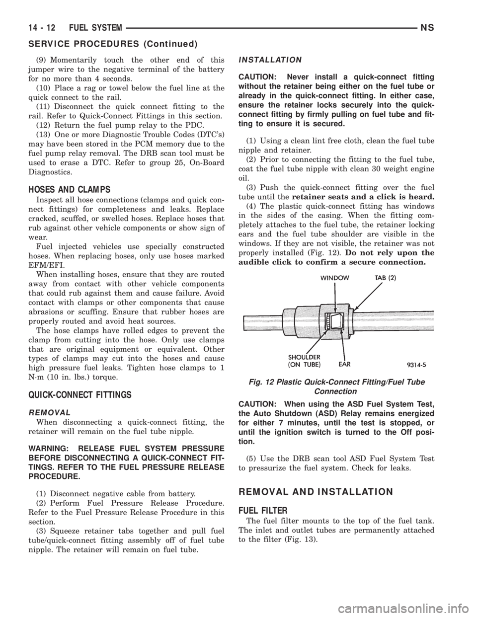
(4) The plastic quick-connect fitting has windows
in the sides of the casing. When the fitting com-
pletely attaches to the fuel tube, the retainer locking
ears and the fuel tube shoulder are visible in the
windows. If they are not visible, the retainer was not
properly installed (Fig. 12).Do not rely upon the
audible click to confirm a secure connection.
CAUTION: When using the ASD Fuel System Test,
the Auto Shutdown (ASD) Relay remains energized
for either 7 minutes, until the test is stopped, or
until the ignition switch is turned to the Off posi-
tion.
(5) Use the DRB scan tool ASD Fuel System Test
to pressurize the fuel system. Check for leaks.
REMOVAL AND INSTALLATION
FUEL FILTER
The fuel filter mounts to the top of the fuel tank.
The inlet and outlet tubes are permanently attached
to the filter (Fig. 13).
Fig. 12 Plastic Quick-Connect Fitting/Fuel Tube
Connection
14 - 12 FUEL SYSTEMNS
SERVICE PROCEDURES (Continued)
Page 1343 of 1938
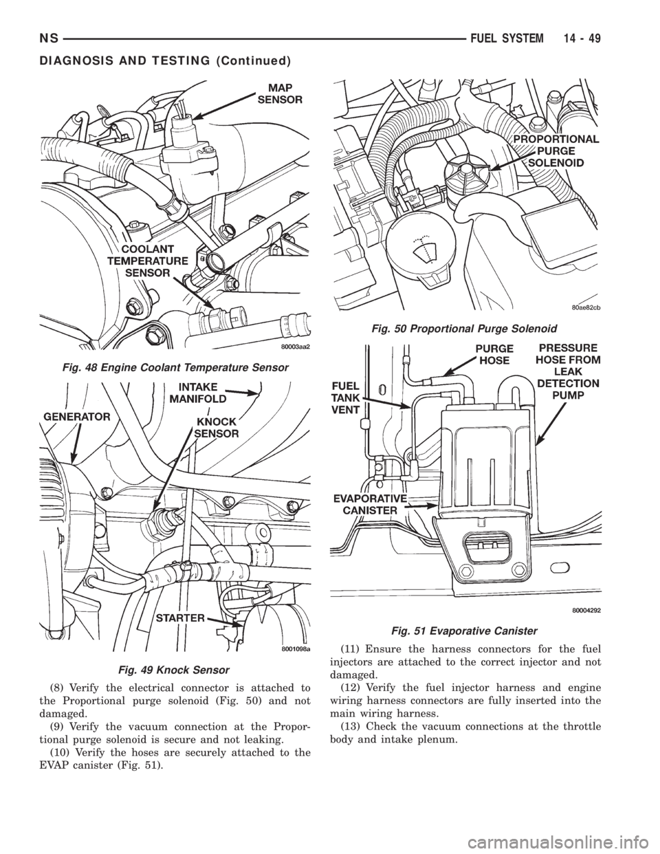
(8) Verify the electrical connector is attached to
the Proportional purge solenoid (Fig. 50) and not
damaged.
(9) Verify the vacuum connection at the Propor-
tional purge solenoid is secure and not leaking.
(10) Verify the hoses are securely attached to the
EVAP canister (Fig. 51).(11) Ensure the harness connectors for the fuel
injectors are attached to the correct injector and not
damaged.
(12) Verify the fuel injector harness and engine
wiring harness connectors are fully inserted into the
main wiring harness.
(13) Check the vacuum connections at the throttle
body and intake plenum.
Fig. 48 Engine Coolant Temperature Sensor
Fig. 49 Knock Sensor
Fig. 50 Proportional Purge Solenoid
Fig. 51 Evaporative Canister
NSFUEL SYSTEM 14 - 49
DIAGNOSIS AND TESTING (Continued)
Page 1346 of 1938
VISUAL INSPECTIONÐ3.0L ENGINE
A visual inspection for loose, disconnected, or mis-
routed wires and hoses should be made before
attempting to diagnose or service the fuel injection
system. A visual check helps save unnecessary test
and diagnostic time. A thorough visual inspection will
include the following checks:(1) Check for correct spark plug cable routing.
Ensure that the cables are completely connected to
the spark plugs and distributor.
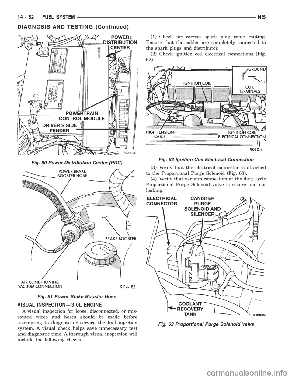
(2) Check ignition coil electrical connections (Fig.
62).
(3) Verify that the electrical connector is attached
to the Proportional Purge Solenoid (Fig. 63).
(4) Verify that vacuum connection at the duty cycle
Proportional Purge Solenoid valve is secure and not
leaking.
Fig. 60 Power Distribution Center (PDC)
Fig. 61 Power Brake Booster Hose
Fig. 62 Ignition Coil Electrical Connection
Fig. 63 Proportional Purge Solenoid Valve
14 - 52 FUEL SYSTEMNS
DIAGNOSIS AND TESTING (Continued)
Page 1347 of 1938
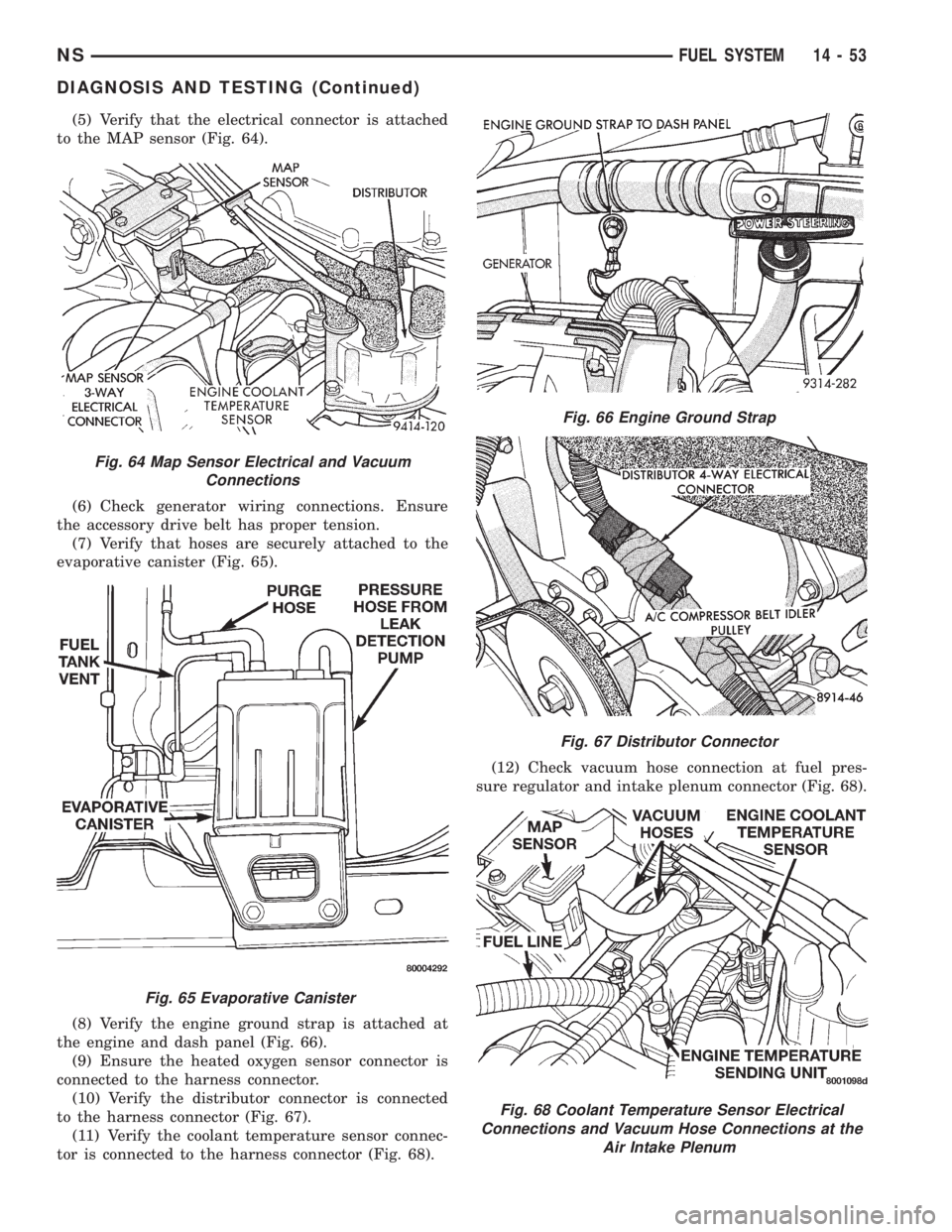
(5) Verify that the electrical connector is attached
to the MAP sensor (Fig. 64).
(6) Check generator wiring connections. Ensure
the accessory drive belt has proper tension.
(7) Verify that hoses are securely attached to the
evaporative canister (Fig. 65).
(8) Verify the engine ground strap is attached at
the engine and dash panel (Fig. 66).
(9) Ensure the heated oxygen sensor connector is
connected to the harness connector.
(10) Verify the distributor connector is connected
to the harness connector (Fig. 67).
(11) Verify the coolant temperature sensor connec-
tor is connected to the harness connector (Fig. 68).(12) Check vacuum hose connection at fuel pres-
sure regulator and intake plenum connector (Fig. 68).
Fig. 64 Map Sensor Electrical and Vacuum
Connections
Fig. 65 Evaporative Canister
Fig. 66 Engine Ground Strap
Fig. 67 Distributor Connector
Fig. 68 Coolant Temperature Sensor Electrical
Connections and Vacuum Hose Connections at the
Air Intake Plenum
NSFUEL SYSTEM 14 - 53
DIAGNOSIS AND TESTING (Continued)
Page 1348 of 1938
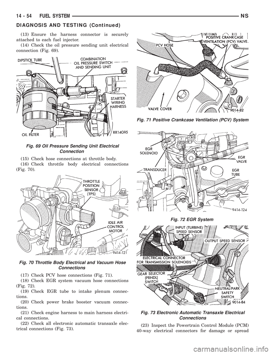
(13) Ensure the harness connector is securely
attached to each fuel injector.
(14) Check the oil pressure sending unit electrical
connection (Fig. 69).
(15) Check hose connections at throttle body.
(16) Check throttle body electrical connections
(Fig. 70).
(17) Check PCV hose connections (Fig. 71).
(18) Check EGR system vacuum hose connections
(Fig. 72).
(19) Check EGR tube to intake plenum connec-
tions.
(20) Check power brake booster vacuum connec-
tions.
(21) Check engine harness to main harness electri-
cal connections.
(22) Check all electronic automatic transaxle elec-
trical connections (Fig. 73).(23) Inspect the Powertrain Control Module (PCM)
40-way electrical connectors for damage or spread
Fig. 69 Oil Pressure Sending Unit Electrical
Connection
Fig. 70 Throttle Body Electrical and Vacuum Hose
Connections
Fig. 71 Positive Crankcase Ventilation (PCV) System
Fig. 72 EGR System
Fig. 73 Electronic Automatic Transaxle Electrical
Connections
14 - 54 FUEL SYSTEMNS
DIAGNOSIS AND TESTING (Continued)
Page 1350 of 1938
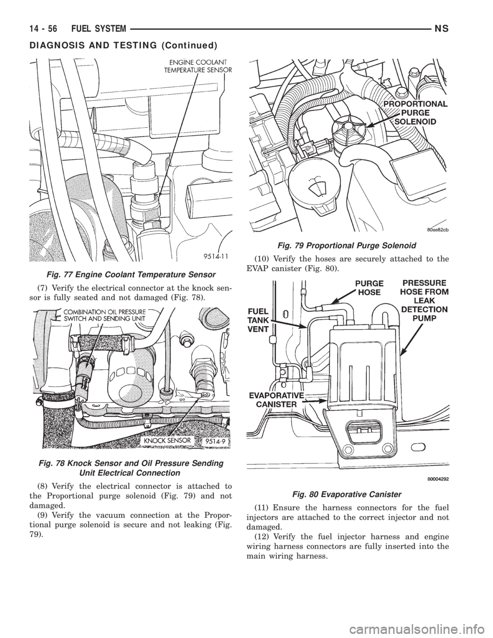
(7) Verify the electrical connector at the knock sen-
sor is fully seated and not damaged (Fig. 78).
(8) Verify the electrical connector is attached to
the Proportional purge solenoid (Fig. 79) and not
damaged.
(9) Verify the vacuum connection at the Propor-
tional purge solenoid is secure and not leaking (Fig.
79).(10) Verify the hoses are securely attached to the
EVAP canister (Fig. 80).
(11) Ensure the harness connectors for the fuel
injectors are attached to the correct injector and not
damaged.
(12) Verify the fuel injector harness and engine
wiring harness connectors are fully inserted into the
main wiring harness.
Fig. 77 Engine Coolant Temperature Sensor
Fig. 78 Knock Sensor and Oil Pressure Sending
Unit Electrical Connection
Fig. 79 Proportional Purge Solenoid
Fig. 80 Evaporative Canister
14 - 56 FUEL SYSTEMNS
DIAGNOSIS AND TESTING (Continued)
Page 1374 of 1938
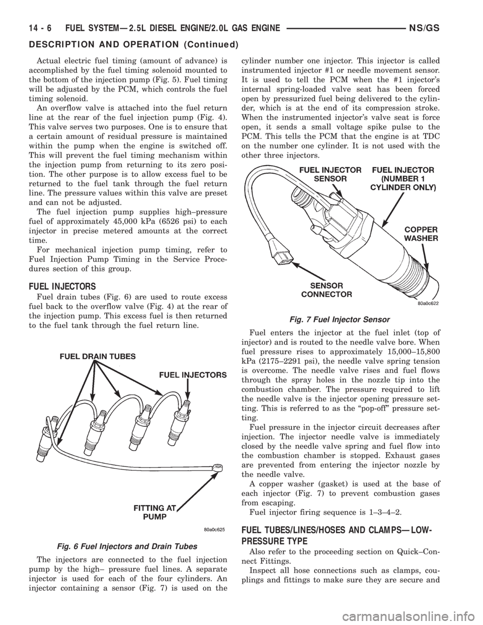
Actual electric fuel timing (amount of advance) is
accomplished by the fuel timing solenoid mounted to
the bottom of the injection pump (Fig. 5). Fuel timing
will be adjusted by the PCM, which controls the fuel
timing solenoid.
An overflow valve is attached into the fuel return
line at the rear of the fuel injection pump (Fig. 4).
This valve serves two purposes. One is to ensure that
a certain amount of residual pressure is maintained
within the pump when the engine is switched off.
This will prevent the fuel timing mechanism within
the injection pump from returning to its zero posi-
tion. The other purpose is to allow excess fuel to be
returned to the fuel tank through the fuel return
line. The pressure values within this valve are preset
and can not be adjusted.
The fuel injection pump supplies high±pressure
fuel of approximately 45,000 kPa (6526 psi) to each
injector in precise metered amounts at the correct
time.
For mechanical injection pump timing, refer to
Fuel Injection Pump Timing in the Service Proce-
dures section of this group.
FUEL INJECTORS
Fuel drain tubes (Fig. 6) are used to route excess
fuel back to the overflow valve (Fig. 4) at the rear of
the injection pump. This excess fuel is then returned
to the fuel tank through the fuel return line.
The injectors are connected to the fuel injection
pump by the high± pressure fuel lines. A separate
injector is used for each of the four cylinders. An
injector containing a sensor (Fig. 7) is used on thecylinder number one injector. This injector is called
instrumented injector #1 or needle movement sensor.
It is used to tell the PCM when the #1 injector's
internal spring-loaded valve seat has been forced
open by pressurized fuel being delivered to the cylin-
der, which is at the end of its compression stroke.
When the instrumented injector's valve seat is force
open, it sends a small voltage spike pulse to the
PCM. This tells the PCM that the engine is at TDC
on the number one cylinder. It is not used with the
other three injectors.
Fuel enters the injector at the fuel inlet (top of
injector) and is routed to the needle valve bore. When
fuel pressure rises to approximately 15,000±15,800
kPa (2175±2291 psi), the needle valve spring tension
is overcome. The needle valve rises and fuel flows
through the spray holes in the nozzle tip into the
combustion chamber. The pressure required to lift
the needle valve is the injector opening pressure set-
ting. This is referred to as the ªpop-offº pressure set-
ting.
Fuel pressure in the injector circuit decreases after
injection. The injector needle valve is immediately
closed by the needle valve spring and fuel flow into
the combustion chamber is stopped. Exhaust gases
are prevented from entering the injector nozzle by
the needle valve.
A copper washer (gasket) is used at the base of
each injector (Fig. 7) to prevent combustion gases
from escaping.
Fuel injector firing sequence is 1±3±4±2.
FUEL TUBES/LINES/HOSES AND CLAMPSÐLOW-
PRESSURE TYPE
Also refer to the proceeding section on Quick±Con-
nect Fittings.
Inspect all hose connections such as clamps, cou-
plings and fittings to make sure they are secure andFig. 6 Fuel Injectors and Drain Tubes
Fig. 7 Fuel Injector Sensor
14 - 6 FUEL SYSTEMÐ2.5L DIESEL ENGINE/2.0L GAS ENGINENS/GS
DESCRIPTION AND OPERATION (Continued)
Page 1375 of 1938
leaks are not present. The component should be
replaced immediately if there is any evidence of deg-
radation that could result in failure.
Never attempt to repair a plastic fuel line/tube or a
quick±connect fitting. Replace complete line/tube as
necessary.
Avoid contact of any fuel tubes/hoses with other
vehicle components that could cause abrasions or
scuffing. Be sure that the fuel lines/tubes are prop-
erly routed to prevent pinching and to avoid heat
sources.
The lines/tubes/hoses are of a special construction.
If it is necessary to replace these lines/tubes/hoses,
use only original equipment type.
The hose clamps used to secure the rubber hoses
are of a special rolled edge construction. This con-
struction is used to prevent the edge of the clamp
from cutting into the hose. Only these rolled edge
type clamps may be used in this system. All other
types of clamps may cut into the hoses and cause
fuel leaks.
Where a rubber hose is joined to a metal tube
(staked), do not attempt to repair. Replace entire
line/tube assembly.
Use new original equipment type hose clamps.
Tighten hose clamps to 2 N´m (20 in. lbs.) torque.
QUICK-CONNECT FITTINGSÐLOW PRESSURE
TYPE
Different types of quick-connect fittings are used to
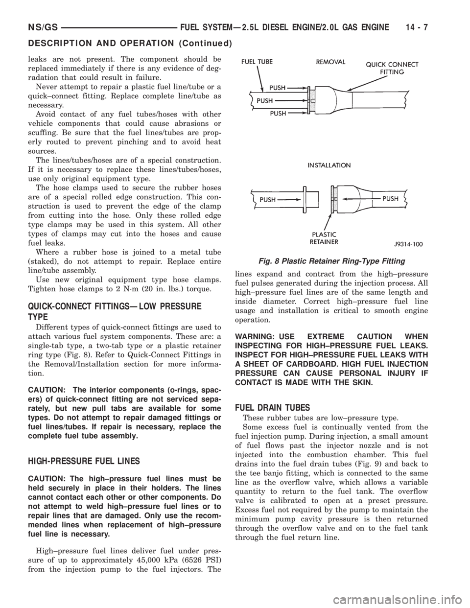
attach various fuel system components. These are: a
single-tab type, a two-tab type or a plastic retainer
ring type (Fig. 8). Refer to Quick-Connect Fittings in
the Removal/Installation section for more informa-
tion.
CAUTION: The interior components (o-rings, spac-
ers) of quick-connect fitting are not serviced sepa-
rately, but new pull tabs are available for some
types. Do not attempt to repair damaged fittings or
fuel lines/tubes. If repair is necessary, replace the
complete fuel tube assembly.
HIGH-PRESSURE FUEL LINES
CAUTION: The high±pressure fuel lines must be
held securely in place in their holders. The lines
cannot contact each other or other components. Do
not attempt to weld high±pressure fuel lines or to
repair lines that are damaged. Only use the recom-
mended lines when replacement of high±pressure
fuel line is necessary.
High±pressure fuel lines deliver fuel under pres-
sure of up to approximately 45,000 kPa (6526 PSI)
from the injection pump to the fuel injectors. Thelines expand and contract from the high±pressure
fuel pulses generated during the injection process. All
high±pressure fuel lines are of the same length and
inside diameter. Correct high±pressure fuel line
usage and installation is critical to smooth engine
operation.
WARNING: USE EXTREME CAUTION WHEN
INSPECTING FOR HIGH±PRESSURE FUEL LEAKS.
INSPECT FOR HIGH±PRESSURE FUEL LEAKS WITH
A SHEET OF CARDBOARD. HIGH FUEL INJECTION
PRESSURE CAN CAUSE PERSONAL INJURY IF
CONTACT IS MADE WITH THE SKIN.
FUEL DRAIN TUBES
These rubber tubes are low±pressure type.
Some excess fuel is continually vented from the
fuel injection pump. During injection, a small amount
of fuel flows past the injector nozzle and is not
injected into the combustion chamber. This fuel
drains into the fuel drain tubes (Fig. 9) and back to
the tee banjo fitting, which is connected to the same
line as the overflow valve, which allows a variable
quantity to return to the fuel tank. The overflow
valve is calibrated to open at a preset pressure.
Excess fuel not required by the pump to maintain the
minimum pump cavity pressure is then returned
through the overflow valve and on to the fuel tank
through the fuel return line.
Fig. 8 Plastic Retainer Ring-Type Fitting
NS/GSFUEL SYSTEMÐ2.5L DIESEL ENGINE/2.0L GAS ENGINE 14 - 7
DESCRIPTION AND OPERATION (Continued)
Page 1381 of 1938
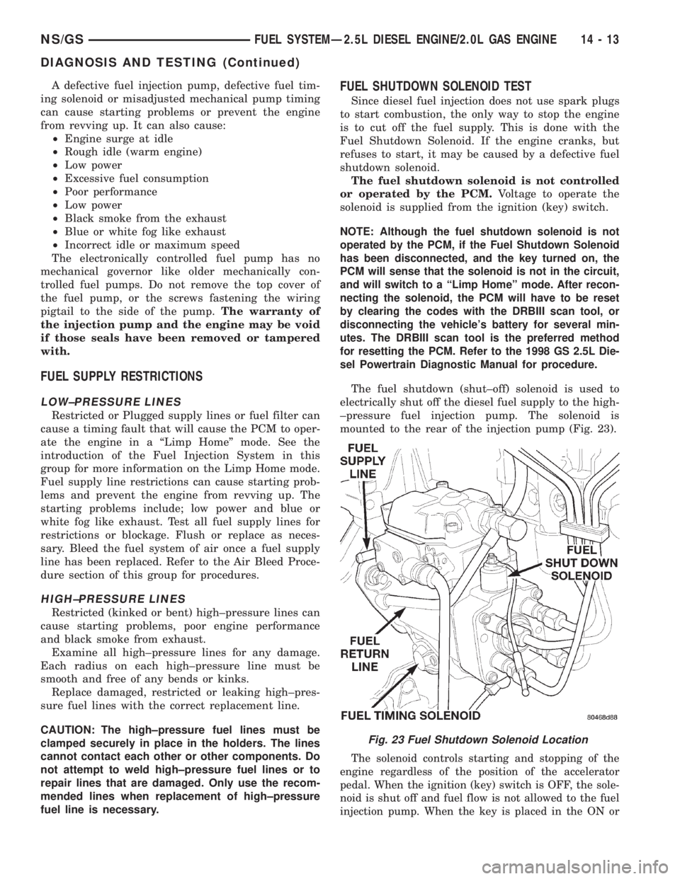
A defective fuel injection pump, defective fuel tim-
ing solenoid or misadjusted mechanical pump timing
can cause starting problems or prevent the engine
from revving up. It can also cause:
²Engine surge at idle
²Rough idle (warm engine)
²Low power
²Excessive fuel consumption
²Poor performance
²Low power
²Black smoke from the exhaust
²Blue or white fog like exhaust
²Incorrect idle or maximum speed
The electronically controlled fuel pump has no
mechanical governor like older mechanically con-
trolled fuel pumps. Do not remove the top cover of
the fuel pump, or the screws fastening the wiring
pigtail to the side of the pump.The warranty of
the injection pump and the engine may be void
if those seals have been removed or tampered
with.
FUEL SUPPLY RESTRICTIONS
LOW±PRESSURE LINES
Restricted or Plugged supply lines or fuel filter can
cause a timing fault that will cause the PCM to oper-
ate the engine in a ªLimp Homeº mode. See the
introduction of the Fuel Injection System in this
group for more information on the Limp Home mode.
Fuel supply line restrictions can cause starting prob-
lems and prevent the engine from revving up. The
starting problems include; low power and blue or
white fog like exhaust. Test all fuel supply lines for
restrictions or blockage. Flush or replace as neces-
sary. Bleed the fuel system of air once a fuel supply
line has been replaced. Refer to the Air Bleed Proce-
dure section of this group for procedures.
HIGH±PRESSURE LINES
Restricted (kinked or bent) high±pressure lines can
cause starting problems, poor engine performance
and black smoke from exhaust.
Examine all high±pressure lines for any damage.
Each radius on each high±pressure line must be
smooth and free of any bends or kinks.
Replace damaged, restricted or leaking high±pres-
sure fuel lines with the correct replacement line.
CAUTION: The high±pressure fuel lines must be
clamped securely in place in the holders. The lines
cannot contact each other or other components. Do
not attempt to weld high±pressure fuel lines or to
repair lines that are damaged. Only use the recom-
mended lines when replacement of high±pressure
fuel line is necessary.
FUEL SHUTDOWN SOLENOID TEST
Since diesel fuel injection does not use spark plugs
to start combustion, the only way to stop the engine
is to cut off the fuel supply. This is done with the
Fuel Shutdown Solenoid. If the engine cranks, but
refuses to start, it may be caused by a defective fuel
shutdown solenoid.
The fuel shutdown solenoid is not controlled
or operated by the PCM.Voltage to operate the
solenoid is supplied from the ignition (key) switch.
NOTE: Although the fuel shutdown solenoid is not
operated by the PCM, if the Fuel Shutdown Solenoid
has been disconnected, and the key turned on, the
PCM will sense that the solenoid is not in the circuit,
and will switch to a ªLimp Homeº mode. After recon-
necting the solenoid, the PCM will have to be reset
by clearing the codes with the DRBIII scan tool, or
disconnecting the vehicle's battery for several min-
utes. The DRBIII scan tool is the preferred method
for resetting the PCM. Refer to the 1998 GS 2.5L Die-
sel Powertrain Diagnostic Manual for procedure.
The fuel shutdown (shut±off) solenoid is used to
electrically shut off the diesel fuel supply to the high-
±pressure fuel injection pump. The solenoid is
mounted to the rear of the injection pump (Fig. 23).
The solenoid controls starting and stopping of the
engine regardless of the position of the accelerator
pedal. When the ignition (key) switch is OFF, the sole-
noid is shut off and fuel flow is not allowed to the fuel
injection pump. When the key is placed in the ON or
Fig. 23 Fuel Shutdown Solenoid Location
NS/GSFUEL SYSTEMÐ2.5L DIESEL ENGINE/2.0L GAS ENGINE 14 - 13
DIAGNOSIS AND TESTING (Continued)
Page 1382 of 1938

START positions, fuel supply is allowed at the injec-
tion pump.
(1) Disconnect the electrical pigtail connector (test
connector) (Fig. 23) from the main engine wiring har-
ness. Do not disconnect wiring directly at solenoid.
(2) Connect the leads of a voltmeter between a
good ground and the disconnected engine wiring har-
ness.
(3) Turn the key to the ON position. Do not
attempt to start engine.
(4) 12V+ should be observed at wiring harness. If
not, refer to Group 8, Wiring for wiring schematics
and repair as necessary.
(5) T
urn the key to the START position. 12V+ should
be observed at wiring harness. If not, refer to Group 8,
Wiring for wiring schematics and repair as necessary.
The fault may be in the ignition (key) switch.
12V+ must be observed in both the ON and START
positions. If 12V+ was observed, proceed to the next
step.
(6) With key still in the ON position, connect and
disconnect the wiring harness to the solenoid. As this
is done, a clicking noise should be heard coming from
the solenoid. If not, replace solenoid. Refer to Fuel
Shutdown Solenoid in the Removal/Installation sec-
tion of this group for procedures.
HIGH-PRESSURE FUEL LINE LEAK TEST
High±pressure fuel line leaks can cause starting
problems and poor engine performance.
WARNING: DUE TO EXTREME FUEL PRESSURES
OF UP TO 45,000 KPA (6526 PSI), USE EXTREME
CAUTION WHEN INSPECTING FOR HIGH±PRESSURE
FUEL LEAKS. DO NOT GET YOUR HAND, OR ANY
PART OF YOUR BODY NEAR A SUSPECTED LEAK.
INSPECT FOR HIGH±PRESSURE FUEL LEAKS WITH
A SHEET OF CARDBOARD. HIGH FUEL INJECTION
PRESSURE CAN CAUSE PERSONAL INJURY IF
CONTACT IS MADE WITH THE SKIN.
Start the engine. Move the cardboard over the
high±pressure fuel lines and check for fuel spray onto
the cardboard (Fig. 24). If a high±pressure line con-
nection is leaking, bleed the system and tighten the
connection. Refer to the Air Bleed Procedure in this
group for procedures. Replace damaged, restricted or
leaking high±pressure fuel lines with the correct
replacement line.
CAUTION: The high±pressure fuel lines must be
clamped securely in place in the holders. The lines
cannot contact each other or other components. Do
not attempt to weld high±pressure fuel lines or to
repair lines that are damaged. Only use the recom-
mended lines when replacement of high±pressure
fuel line is necessary.
WASTEGATE (TURBOCHARGER)
Refer to Group 11, Exhaust System and Intake
Manifold for information.
SERVICE PROCEDURES
AIR BLEED PROCEDURES
AIR BLEEDING AT FUEL FILTER
A certain amount of air may become trapped in the
fuel system when fuel system components are ser-
viced or replaced. Bleed the system as needed after
fuel system service according to the following proce-
dures.
WARNING: DO NOT BLEED AIR FROM THE FUEL
SYSTEM OF A HOT ENGINE. DO NOT ALLOW FUEL
TO SPRAY ONTO THE EXHAUST MANIFOLD WHEN
BLEEDING AIR FROM THE FUEL SYSTEM.
Some air enters the fuel system when the fuel fil-
ter or injection pump supply line is changed. This
small amount of air is vented automatically from the
injection pump through the fuel drain manifold tubes
if the filter was changed according to instructions.
Ensure the bowl of the fuel filter/water separator is
full of fuel
It may be necessary to manually bleed the system
if:
²The bowl of the fuel filter/water separator is not
partially filled before installation of a new filter
²The injection pump is replaced
Fig. 24 Typical Test for Leaks with Cardboard
14 - 14 FUEL SYSTEMÐ2.5L DIESEL ENGINE/2.0L GAS ENGINENS/GS
DIAGNOSIS AND TESTING (Continued)