ECU CHRYSLER VOYAGER 1996 Owners Manual
[x] Cancel search | Manufacturer: CHRYSLER, Model Year: 1996, Model line: VOYAGER, Model: CHRYSLER VOYAGER 1996Pages: 1938, PDF Size: 55.84 MB
Page 1565 of 1938
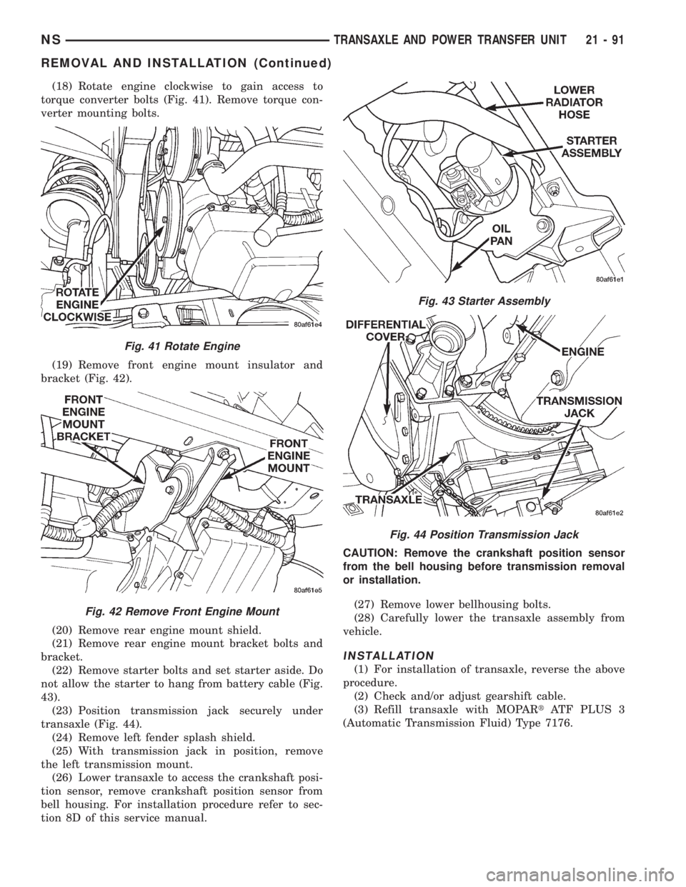
(18) Rotate engine clockwise to gain access to
torque converter bolts (Fig. 41). Remove torque con-
verter mounting bolts.
(19) Remove front engine mount insulator and
bracket (Fig. 42).
(20) Remove rear engine mount shield.
(21) Remove rear engine mount bracket bolts and
bracket.
(22) Remove starter bolts and set starter aside. Do
not allow the starter to hang from battery cable (Fig.
43).
(23) Position transmission jack securely under
transaxle (Fig. 44).
(24) Remove left fender splash shield.
(25) With transmission jack in position, remove
the left transmission mount.
(26) Lower transaxle to access the crankshaft posi-
tion sensor, remove crankshaft position sensor from
bell housing. For installation procedure refer to sec-
tion 8D of this service manual.CAUTION: Remove the crankshaft position sensor
from the bell housing before transmission removal
or installation.
(27) Remove lower bellhousing bolts.
(28) Carefully lower the transaxle assembly from
vehicle.
INSTALLATION
(1) For installation of transaxle, reverse the above
procedure.
(2) Check and/or adjust gearshift cable.
(3) Refill transaxle with MOPARtATF PLUS 3
(Automatic Transmission Fluid) Type 7176.
Fig. 41 Rotate Engine
Fig. 42 Remove Front Engine Mount
Fig. 43 Starter Assembly
Fig. 44 Position Transmission Jack
NSTRANSAXLE AND POWER TRANSFER UNIT 21 - 91
REMOVAL AND INSTALLATION (Continued)
Page 1668 of 1938

DIFFERENTIAL BEARING RETAINER AXLE
SEAL
REMOVAL
(1) Remove axle shaft. Refer to Group 2, Suspen-
sion and Driveshafts for service procedures.
(2) Insert a flat±blade pry tool into the axle seal
bore.
(3) Using the pry tool, carefully pop out the seal
taking care not to nick the seal bore.
INSTALLATION
(1) Clean axle shaft seal bore of any excess seal-
ant.
(2) Align axle shaft seal with axle shaft seal bore.
(3) Position axle seal at extension housing.
(4) Using Tool L-4520 and Tool C-4171, tap seal
into position.
SHIFT SHAFT SEALS
It isnotnecessary to remove the shift shaft cover
from the transaxle to service the shift shaft seals.
REMOVAL
(1) Remove the shift lever from the seal that is to
be serviced. Refer to shift lever removal for service
procedure.
(2) Using a pick tool, pry up on the shift shaft seal
and remove seal from bore.
INSTALLATION
(1) Position new shift shaft seal in bore.
(2) Install shift shaft seal into bore using an
appropriate size deep±well socket.
TRANSAXLE
The following items can be serviced without remov-
ing the transaxle from the vehicle:
²Gearshift housing
²5th speed synchronizer
²5th speed gear
²Roller detents and springs
²Speedometer pinion
²Vehicle speed sensor
²Bearing retainer plate.
²All external covers
²Shift shaft seals
²Axle shaft seals
To service any other component of the A-598 tran-
saxle you must remove it from the vehicle.
REMOVAL
(1) Disconnect battery negative cable.
(2) Remove air intake hose. Disconnect air mass
meter connector.
(3) Remove intercooler hose.(4) Remove connectors for back-up lamp (Fig. 28)
and crank position sensor (Fig. 29).
(5) Remove crank position sensor (2.5L VM Diesel
only).
(6) Remove wiring harness bracket at transaxle
(Fig. 30).
(7) Remove crossover and shift selector cables (Fig.
31).
(8) Remove the two top bolts at the rear engine
mount bracket.
(9) Remove bolts securing the coolant reservoir to
the top of the engine. Move the coolant reservoir out
of the way.
(10) Install an engine support chain to the cylinder
head assembly (Fig. 32).
Fig. 28 Back-up Lamp Connector
Fig. 29 Crankshaft Position Sensor
21 - 12 A±598 MANUAL TRANSAXLENS/GS
REMOVAL AND INSTALLATION (Continued)
Page 1731 of 1938
BODY
CONTENTS
page page
BODY COMPONENT SERVICE.............. 22
GENERAL SERVICE INFORMATION........... 1
PAINT.................................. 2SEATS .................................. 9
STATIONARY GLASS....................... 4
GENERAL SERVICE INFORMATION
INDEX
page
GENERAL INFORMATION
SAFETY PRECAUTIONS AND WARNINGS...... 1
GENERAL INFORMATION
SAFETY PRECAUTIONS AND WARNINGS
WARNING: EYE PROTECTION SHOULD BE USED
WHEN SERVICING GLASS COMPONENTS. PER-
SONAL INJURY CAN RESULT.
USE A OSHA APPROVED BREATHING FILTER
WHEN SPRAYING PAINT OR SOLVENTS IN A CON-
FINED AREA. PERSONAL INJURY CAN RESULT.
AVOID PROLONGED SKIN CONTACT WITH
PETROLEUM OR ALCOHOL± BASED CLEANING
SOLVENTS. PERSONAL INJURY CAN RESULT.
DO NOT STAND UNDER A HOISTED VEHICLE
THAT IS NOT PROPERLY SUPPORTED ON SAFETY
STANDS. PERSONAL INJURY CAN RESULT.
CAUTION: When holes must be drilled or punched
in an inner body panel, verify depth of space to the
outer body panel, electrical wiring, or other compo-
nents. Damage to vehicle can result.
Do not weld exterior panels unless combustible
material on the interior of vehicle is removed from
the repair area. Fire or hazardous conditions, can
result.
Always have a fire extinguisher ready for use
when welding.
Disconnect the negative (-) cable clamp from the
battery when servicing electrical components that
are live when the ignition is OFF. Damage to electri-
cal system can result.Do not use abrasive chemicals or compounds on
painted surfaces. Damage to finish can result.
Do not use harsh alkaline based cleaning sol-
vents on painted or upholstered surfaces. Damage
to finish or color can result.
Do not hammer or pound on plastic trim panel
when servicing interior trim. Plastic panels can
break.
Chrysler Corporation uses many different types of
push-in fasteners to secure the interior and exterior
trim to the body. Most of these fasteners can be
reused to assemble the trim during various repair
procedures. At times, a push-in fastener cannot be
removed without damaging the fastener or the com-
ponent it is holding. If it is not possible to remove a
fastener without damaging a component or body, cut
or break the fastener and use a new one when
installing the component. Never pry or pound on a
plastic or pressed-board trim component. Using a
suitable fork-type prying device, pry the fastener
from the retaining hole behind the component being
removed. When installing, verify fastener alignment
with the retaining hole by hand. Push directly on or
over the fastener until it seats. Apply a low-force pull
to the panel to verify that it is secure.
When it is necessary to remove components to ser-
vice another, it should not be necessary to apply
excessive force or bend a component to remove it.
Before damaging a trim component, verify hidden
fasteners or captured edges holding the component in
place.
NSBODY 23 - 1
Page 1734 of 1938

STATIONARY GLASS
INDEX
page page
DESCRIPTION AND OPERATION
SAFETY PRECAUTIONS................... 4
REMOVAL AND INSTALLATION
BODY SIDE/SLIDING DOOR STATIONARY
GLASS............................... 6REAR WINDOW.......................... 7
WINDSHIELD............................ 4
DESCRIPTION AND OPERATION
SAFETY PRECAUTIONS
WARNING: DO NOT OPERATE THE VEHICLE
WITHIN 24 HOURS OF WINDSHIELD INSTALLATION.
IT TAKES AT LEAST 24 HOURS FOR URETHANE
ADHESIVE TO CURE. IF IT IS NOT CURED, THE
WINDSHIELD MAY NOT PERFORM PROPERLY IN
AN ACCIDENT.
URETHANE ADHESIVES ARE APPLIED AS A SYS-
TEM. USE GLASS CLEANER, GLASS PREP SOL-
VENT, GLASS PRIMER, PVC (VINYL) PRIMER AND
PINCHWELD (FENCE) PRIMER PROVIDED BY THE
ADHESIVE MANUFACTURER. IF NOT, STRUCTURAL
INTEGRITY COULD BE COMPROMISED.
CHRYSLER DOES NOT RECOMMEND GLASS
ADHESIVE BY BRAND. TECHNICIANS SHOULD
REVIEW PRODUCT LABELS AND TECHNICAL DATA
SHEETS, AND USE ONLY ADHESIVES THAT THEIR
MANUFACTURES WARRANT WILL RESTORE A
VEHICLE TO THE REQUIREMENTS OF FMVSS 212.
TECHNICIANS SHOULD ALSO INSURE THAT PRIM-
ERS AND CLEANERS ARE COMPATIBLE WITH THE
PARTICULAR ADHESIVE USED.
BE SURE TO REFER TO THE URETHANE MANU-
FACTURER'S DIRECTIONS FOR CURING TIME
SPECIFICATIONS, AND DO NOT USE ADHESIVE
AFTER ITS EXPIRATION DATE.
VAPORS THAT ARE EMITTED FROM THE URE-
THANE ADHESIVE OR PRIMER COULD CAUSE
PERSONAL INJURY. USE THEM IN A WELL-VENTI-
LATED AREA.
SKIN CONTACT WITH URETHANE ADHESIVE
SHOULD BE AVOIDED. PERSONAL INJURY MAY
RESULT.
ALWAYS WEAR EYE AND HAND PROTECTION
WHEN WORKING WITH GLASS.
CAUTION: Protect all painted and trimmed surfaces
from coming in contact with urethane or primers.Be careful not to damage painted surfaces when
removing moldings or cutting urethane around
windshield.
It is difficult to salvage a windshield during the
removal operation. The windshield is part of the
structural support for the roof. The urethane bonding
used to secure the windshield to the fence is difficult
to cut or clean from any surface. If the moldings are
set in urethane, it would also be unlikely they could
be salvaged. Before removing the windshield, check
the availability of the windshield and moldings from
the parts supplier.
REMOVAL AND INSTALLATION
WINDSHIELD
The urethane adhesive holding the windshield to
the opening pinch weld (fence) can be cut using a
sharp cold knife from the exterior of the vehicle.
Using the cold knife method is effective if the wind-
shield is already broken. If the glass must be sal-
vaged, cutting the urethane adhesive from the
interior of the vehicle using a reciprocating or oscil-
lating power knife is recommended.
WINDSHIELD REMOVAL ± EXTERIOR METHOD
(1) Remove inside rear view mirror.
(2) Remove windshield wiper arms.
(3) Remove cowl cover.
(4) Remove A-pillar trim panels.
(5) Disconnect wire connectors to windshield
defroster grid.
(6) Place protective covers over instrument panel
and hood.
(7) Remove windshield molding (Fig. 1). Using pli-
ers, pull outward on molding at the bottom of A-pil-
lars.
(8) Using a sharp cold knife, cut urethane adhe-
sive holding the windshield to the A-pillars, roof
header and cowl pinch weld fences (Fig. 2). A power
cutting device can be used if available.
(9) Remove windshield from vehicle.
23 - 4 BODYNS
Page 1754 of 1938
Some water leaks must be tested for a considerable
length of time to become apparent. When a leak
appears, find the highest point of the water track or
drop. The highest point usually will show the point of
entry. After leak point has been found, repair the
leak and water test to verify that the leak has
stopped.
Locating the entry point of water that is leaking
into a cavity between panels can be difficult. The
trapped water may splash or run from the cavity,
often at a distance from the entry point. Most water
leaks of this type become apparent after accelerating,
stopping, turning, or when on an incline.
MIRROR INSPECTION METHOD
When a leak point area is visually obstructed, use
a suitable mirror to gain visual access. A mirror can
also be used to deflect light to a limited-access area
to assist in locating a leak point.
BRIGHT LIGHT LEAK TEST METHOD
Some water leaks in the luggage compartment can
be detected without water testing. Position the vehi-
cle in a brightly lit area. From inside the darkened
luggage compartment inspect around seals and body
seams. If necessary, have a helper direct a drop light
over the suspected leak areas around the luggage
compartment. If light is visible through a normally
sealed location, water could enter through the open-
ing.
PRESSURIZED LEAK TEST METHOD
When a water leak into the passenger compart-
ment cannot be detected by water testing, pressurize
the passenger compartment and soap test exterior of
the vehicle. To pressurize the passenger compart-
ment, close all doors and windows, start engine, and
set heater control to high blower in HEAT position. If
engine can not be started, connect a charger to the
battery to ensure adequate voltage to the blower.
With interior pressurized, apply dish detergent solu-
tion to suspected leak area on the exterior of the
vehicle. Apply detergent solution with spray device or
soft bristle brush. If soap bubbles occur at a body
seam, joint, seal or gasket, the leak entry point could
be at that location.
WIND NOISE
Wind noise is the result of most air leaks. Air leaks
can be caused by poor sealing, improper body compo-
nent alignment, body seam porosity, or missing plugs
in the engine compartment or door hinge pillar areas.
All body sealing points should be airtight in normal
driving conditions. Moving sealing surfaces will not
always seal airtight under all conditions. At times,
side glass or door seals will allow wind noise to be
noticed in the passenger compartment during highcrosswinds. Over compensating on door or glass
adjustments to stop wind noise that occurs under
severe conditions can cause premature seal wear and
excessive closing or latching effort. After a repair pro-
cedure has been performed, test vehicle to verify
noise has stopped before returning vehicle to use.
Wind noise can also be caused by improperly fitted
exterior moldings or body ornamentation. Loose
moldings can flutter, creating a buzzing or chattering
noise. An open cavity or protruding edge can create a
whistling or howling noise. Inspect the exterior of the
vehicle to verify that these conditions do not exist.
VISUAL INSPECTION BEFORE TESTS
Verify that floor and body plugs are in place and
body components are aligned and sealed. If component
alignment or sealing is necessary, refer to the appro-
priate section of this group for proper procedures.
ROAD TESTING WIND NOISE
(1) Drive the vehicle to verify the general location
of the wind noise.
(2) Apply 50 mm (2 in.) masking tape in 150 mm
(6 in.) lengths along weatherstrips, weld seams or
moldings. After each length is applied, drive the vehi-
cle. If noise goes away after a piece of tape is applied,
remove tape, locate, and repair defect.
POSSIBLE CAUSE OF WIND NOISE
²Moldings standing away from body surface can
catch wind and whistle.
²Gaps in sealed areas behind overhanging body
flanges can cause wind-rushing sounds.
²Misaligned movable components.
²Missing or improperly installed plugs in pillars.
²Weld burn through holes.
SERVICE PROCEDURES
HEAT STAKING
(1) Remove trim panel.
(2) Bend or move the trim panel components at
the heat staked joints. Observe the heat staked loca-
tions and/or component seams for looseness.
(3) Heat stake the components.
(a) If the heat staked or component seam loca-
tion is loose, hold the two components tightly
together and using a soldering gun with a flat tip,
melt the material securing the components
together. Do not over heat the affected area, dam-
age to the exterior of the trim panel may occur.
(b) If the heat staked material is broken or miss-
ing, use a hot glue gun to apply new material to
the area to be repaired. The panels that are being
heat staked must be held together while the apply-
ing the glue. Once the new material is in place, it
23 - 24 BODYNS
DIAGNOSIS AND TESTING (Continued)
Page 1762 of 1938
INSTALLATION
NOTE: The screws attaching the door latch to the
door end frame have nylon patches on the threads.
All screws must be replaced when the latch has
been removed.
(1) Place door latch in position on door end frame.
(2) Install screws to hold door latch to door end
frame.
(3) Insert linkage into door latch.
(4) Engage clips to hold linkage to door latch.
(5) Connect wire connector into power door lock
motor, if equipped.
(6) Insert a hex wrench through the elongated hole
located in the door shut face above the latch.
(7) Loosen allen head screw.
(8) Pull outward on the outside door handle and
release.
(9) Tighten allen head screw.
(10) Verify door latch and power door lock opera-
tion.
(11) Install water shield and front door trim panel.
FRONT DOOR LATCH STRIKER
REMOVAL
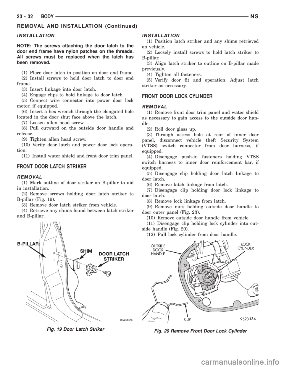
(1) Mark outline of door striker on B-pillar to aid
in installation.
(2) Remove screws holding door latch striker to
B-pillar (Fig. 19).
(3) Remove door latch striker from vehicle.
(4) Retrieve any shims found between latch striker
and B-pillar.
INSTALLATION
(1) Position latch striker and any shims retrieved
on vehicle.
(2) Loosely install screws to hold latch striker to
B-pillar.
(3) Align latch striker to outline on B-pillar made
previously.
(4) Tighten all fasteners.
(5) Verify door fit and operation. Adjust latch
striker as necessary.
FRONT DOOR LOCK CYLINDER
REMOVAL
(1) Remove front door trim panel and water shield
as necessary to gain access to the outside door han-
dle.
(2) Roll door glass up.
(3) Through access hole at rear of inner door
panel, disconnect vehicle theft Security System
(VTSS) switch connector from door harness, if
equipped.
(4) Disengage push-in fasteners holding VTSS
switch harness to inner door reinforcement bar, if
equipped.
(5) Disengage clip holding door latch linkage to
door latch.
(6) Remove latch linkage from latch.
(7) Disengage clip holding door lock linkage to
door latch.
(8) Remove lock linkage from latch.
(9) Remove nuts holding outside door handle to
door outer panel (Fig. 23).
(10) Remove outside door handle from vehicle.
(11) Disengage clip holding lock cylinder into out-
side handle (Fig. 20).
(12) Pull lock cylinder from door handle.
Fig. 19 Door Latch StrikerFig. 20 Remove Front Door Lock Cylinder
23 - 32 BODYNS
REMOVAL AND INSTALLATION (Continued)
Page 1763 of 1938

INSTALLATION
(1) Engage clip into outside handle to hold lock
cylinder.
(2) With link arm toward rear of vehicle, push lock
cylinder into door handle until clip snaps into place
(Fig. 21).
(3) Insert lock linkage into door latch.
(4) Engage clip to hold door lock linkage to latch.
(5) Insert latch linkage into door latch.
(6) Engage clip to hold door latch linkage to latch.
(7) Install push-in fasteners to hold VTSS switch
harness to inner door reinforcement bar, if equipped.
(8) Connect VTSS switch connector into door har-
ness, if equipped.
(9) Verify door latch operation.
(10) Install water shield and door trim panel.
FRONT DOOR OUTER BELT MOLDING
REMOVAL
(1) Remove door trim panel.
(2) Roll door glass down.
(3) Using a hook tool, disengage interlocking lip at
the base of the inward edge of the belt molding (Fig.
22).
(4) Remove belt molding from door.
INSTALLATION
(1) Place belt molding in position on door.
(2) Engage interlocking lip at the base of the
inward edge of the belt molding on door panel.
(3) Install door trim panel.
FRONT DOOR OUTSIDE HANDLE
REMOVAL
(1) Remove front door trim panel and water shield
as necessary to gain access to the outside door han-
dle.
(2) Roll door glass up.(3) Through access hole at rear of inner door
panel, disconnect vehicle theft Security System
(VTSS) switch connector from door harness, if
equipped.
(4) Disengage push-in fasteners holding VTSS
switch harness to inner door reinforcement bar, if
equipped.
(5) Disengage clip holding door latch linkage to
door latch.
(6) Remove latch linkage from latch.
(7) Disengage clip holding door lock linkage to
door latch.
(8) Remove lock linkage from latch.
(9) Remove nuts holding outside door handle to
door outer panel (Fig. 23).
(10) Remove outside door handle from vehicle.
Fig. 21 Install Front Door Lock Cylinder
Fig. 22 Front Door Outer Belt Molding
Fig. 23 Front Door Outside Handle
NSBODY 23 - 33
REMOVAL AND INSTALLATION (Continued)
Page 1771 of 1938
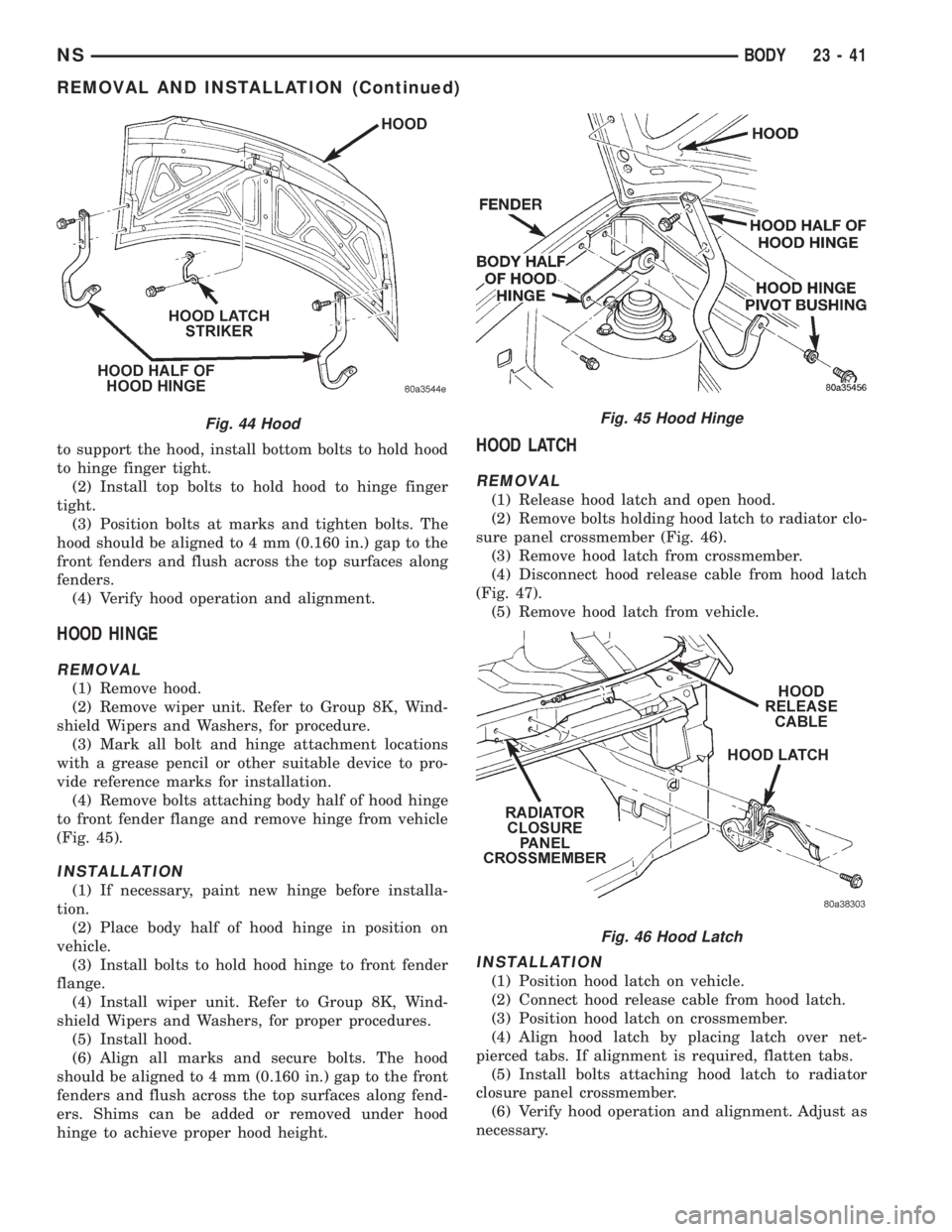
to support the hood, install bottom bolts to hold hood
to hinge finger tight.
(2) Install top bolts to hold hood to hinge finger
tight.
(3) Position bolts at marks and tighten bolts. The
hood should be aligned to 4 mm (0.160 in.) gap to the
front fenders and flush across the top surfaces along
fenders.
(4) Verify hood operation and alignment.
HOOD HINGE
REMOVAL
(1) Remove hood.
(2) Remove wiper unit. Refer to Group 8K, Wind-
shield Wipers and Washers, for procedure.
(3) Mark all bolt and hinge attachment locations
with a grease pencil or other suitable device to pro-
vide reference marks for installation.
(4) Remove bolts attaching body half of hood hinge
to front fender flange and remove hinge from vehicle
(Fig. 45).
INSTALLATION
(1) If necessary, paint new hinge before installa-
tion.
(2) Place body half of hood hinge in position on
vehicle.
(3) Install bolts to hold hood hinge to front fender
flange.
(4) Install wiper unit. Refer to Group 8K, Wind-
shield Wipers and Washers, for proper procedures.
(5) Install hood.
(6) Align all marks and secure bolts. The hood
should be aligned to 4 mm (0.160 in.) gap to the front
fenders and flush across the top surfaces along fend-
ers. Shims can be added or removed under hood
hinge to achieve proper hood height.
HOOD LATCH
REMOVAL
(1) Release hood latch and open hood.
(2) Remove bolts holding hood latch to radiator clo-
sure panel crossmember (Fig. 46).
(3) Remove hood latch from crossmember.
(4) Disconnect hood release cable from hood latch
(Fig. 47).
(5) Remove hood latch from vehicle.
INSTALLATION
(1) Position hood latch on vehicle.
(2) Connect hood release cable from hood latch.
(3) Position hood latch on crossmember.
(4) Align hood latch by placing latch over net-
pierced tabs. If alignment is required, flatten tabs.
(5) Install bolts attaching hood latch to radiator
closure panel crossmember.
(6) Verify hood operation and alignment. Adjust as
necessary.
Fig. 44 HoodFig. 45 Hood Hinge
Fig. 46 Hood Latch
NSBODY 23 - 41
REMOVAL AND INSTALLATION (Continued)
Page 1844 of 1938
EXPANSION VALVE
WARNING: THE REFRIGERATION SYSTEM MUST
BE COMPLETELY EMPTY BEFORE PROCEEDING
WITH THIS OPERATION.
REMOVAL
(1) Disconnect the battery negative cable.
(2) Recover A/C system refrigerant.
(3) Remove the accessory drive belt.
(4) Remove upper generator bracket.
(5) Disconnect generator field wire connector.
(6) Push generator forward.
(7) Remove ground wire at dash panel.
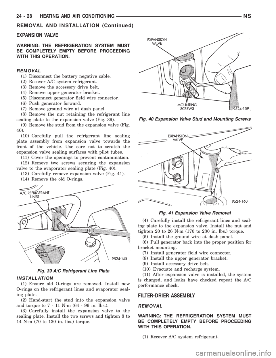
(8) Remove the nut retaining the refrigerant line
sealing plate to the expansion valve (Fig. 39).
(9) Remove the stud from the expansion valve (Fig.
40).
(10) Carefully pull the refrigerant line sealing
plate assembly from expansion valve towards the
front of the vehicle. Use care not to scratch the
expansion valve sealing surfaces with pilot tubes.
(11) Cover the openings to prevent contamination.
(12) Remove two screws securing the expansion
valve to the evaporator sealing plate (Fig. 40).
(13) Carefully remove expansion valve (Fig. 41).
(14) Remove the old O-rings.
INSTALLATION
(1) Ensure old O-rings are removed. Install new
O-rings on the refrigerant lines and evaporator seal-
ing plate.
(2) Hand-start the stud into the expansion valve
and torque to7-11N´m(64-96in.lbs.).
(3) Carefully install the expansion valve to the
sealing plate. Install the two screws and tighten 8 to
14 N´m (70 to 130 in. lbs.) torque.(4) Carefully install the refrigerant lines and seal-
ing plate to the expansion valve. Install the nut and
tighten 20 to 26 N´m (170 to 230 in. lbs.) torque.
(5) Install the ground wire at dash panel.
(6) Pull generator back into the proper position for
bracket mounting.
(7) Install generator field wire connector.
(8) Install the upper generator bracket.
(9) Install accessory drive belt.
(10) Evacuate and recharge system.
(11) After expansion valve is installed, the system
is charged, and leaks have checked repeat the A/C
performance check.
FILTER-DRIER ASSEMBLY
REMOVAL
WARNING: THE REFRIGERATION SYSTEM MUST
BE COMPLETELY EMPTY BEFORE PROCEEDING
WITH THIS OPERATION.
(1) Recover A/C system refrigerant.
Fig. 39 A/C Refrigerant Line Plate
Fig. 40 Expansion Valve Stud and Mounting Screws
Fig. 41 Expansion Valve Removal
24 - 28 HEATING AND AIR CONDITIONINGNS
REMOVAL AND INSTALLATION (Continued)
Page 1846 of 1938
(10) Disconnect the two upper mounts from the
upper reinforcement and the lower mount from the
tunnel.
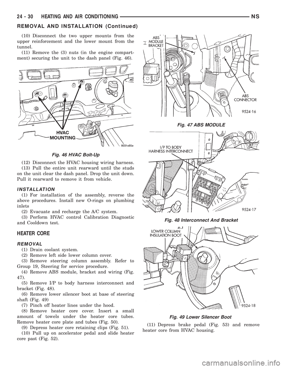
(11) Remove the (3) nuts (in the engine compart-
ment) securing the unit to the dash panel (Fig. 46).
(12) Disconnect the HVAC housing wiring harness.
(13) Pull the entire unit rearward until the studs
on the unit clear the dash panel. Drop the unit down.
Pull it rearward to remove it from vehicle.
INSTALLATION
(1) For installation of the assembly, reverse the
above procedures. Install new O-rings on plumbing
inlets
(2) Evacuate and recharge the A/C system.
(3) Perform HVAC control Calibration Diagnostic
and Cooldown test.
HEATER CORE
REMOVAL
(1) Drain coolant system.
(2) Remove left side lower column cover.
(3) Remove steering column assembly. Refer to
Group 19, Steering for service procedure.
(4) Remove ABS module, bracket and wiring (Fig.
47).
(5) Remove I/P to body harness interconnect and
bracket (Fig. 48).
(6) Remove lower silencer boot at base of steering
shaft (Fig. 49)
(7) Pinch off heater lines under the hood.
(8) Remove heater core cover. Insert a small
amount of towels under the heater core tubes.
Remove heater core plate and tubes (Fig. 50).
(9) Depress heater core retaining clips (Fig. 51).
(10) Pull up on accelerator pedal and slide heater
core past (Fig. 52).(11) Depress brake pedal (Fig. 53) and remove
heater core from HVAC housing.
Fig. 46 HVAC Bolt-Up
Fig. 47 ABS MODULE
Fig. 48 Interconnect And Bracket
Fig. 49 Lower Silencer Boot
24 - 30 HEATING AND AIR CONDITIONINGNS
REMOVAL AND INSTALLATION (Continued)