window CHRYSLER VOYAGER 1996 Manual PDF
[x] Cancel search | Manufacturer: CHRYSLER, Model Year: 1996, Model line: VOYAGER, Model: CHRYSLER VOYAGER 1996Pages: 1938, PDF Size: 55.84 MB
Page 1759 of 1938
INSTALLATION
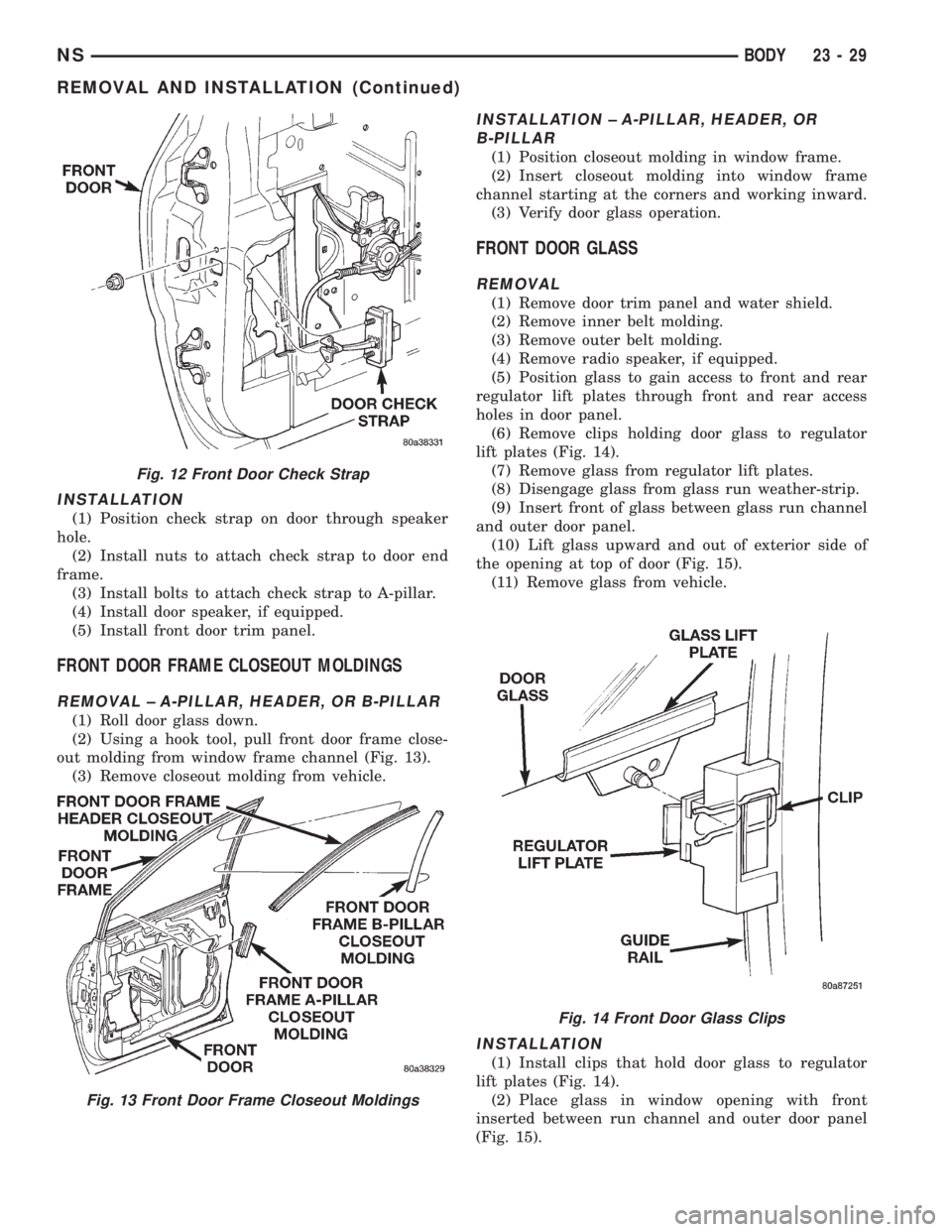
(1) Position check strap on door through speaker
hole.
(2) Install nuts to attach check strap to door end
frame.
(3) Install bolts to attach check strap to A-pillar.
(4) Install door speaker, if equipped.
(5) Install front door trim panel.
FRONT DOOR FRAME CLOSEOUT MOLDINGS
REMOVAL ± A-PILLAR, HEADER, OR B-PILLAR
(1) Roll door glass down.
(2) Using a hook tool, pull front door frame close-
out molding from window frame channel (Fig. 13).
(3) Remove closeout molding from vehicle.
INSTALLATION ± A-PILLAR, HEADER, OR
B-PILLAR
(1) Position closeout molding in window frame.
(2) Insert closeout molding into window frame
channel starting at the corners and working inward.
(3) Verify door glass operation.
FRONT DOOR GLASS
REMOVAL
(1) Remove door trim panel and water shield.
(2) Remove inner belt molding.
(3) Remove outer belt molding.
(4) Remove radio speaker, if equipped.
(5) Position glass to gain access to front and rear
regulator lift plates through front and rear access
holes in door panel.
(6) Remove clips holding door glass to regulator
lift plates (Fig. 14).
(7) Remove glass from regulator lift plates.
(8) Disengage glass from glass run weather-strip.
(9) Insert front of glass between glass run channel
and outer door panel.
(10) Lift glass upward and out of exterior side of
the opening at top of door (Fig. 15).
(11) Remove glass from vehicle.
INSTALLATION
(1) Install clips that hold door glass to regulator
lift plates (Fig. 14).
(2) Place glass in window opening with front
inserted between run channel and outer door panel
(Fig. 15).
Fig. 12 Front Door Check Strap
Fig. 13 Front Door Frame Closeout Moldings
Fig. 14 Front Door Glass Clips
NSBODY 23 - 29
REMOVAL AND INSTALLATION (Continued)
Page 1764 of 1938
INSTALLATION
If outside door handle replacement is necessary,
transfer lock cylinder from the original handle to the
new one.
(1) Place outside door handle in position on vehi-
cle.
(2) Install nuts to hold outside door handle to door
outer panel (Fig. 23).
(3) Insert lock linkage into door latch.
(4) Engage clip to hold door lock linkage to latch.
(5) Insert latch linkage into door latch.
(6) Engage clip to hold door latch linkage to latch.
(7) Install push-in fasteners to hold VTSS switch
harness to inner door reinforcement bar, if equipped.
(8) Connect VTSS switch connector into door har-
ness, if equipped.
(9) Verify door latch operation.
(10) Install water shield and door trim panel.
FRONT DOOR REFLECTOR
REMOVAL
(1) Insert small, flat bladed pry tool between outer
edge of door reflector and HVAC outlet vent.
(2) Pry outward on outer edge of reflector.
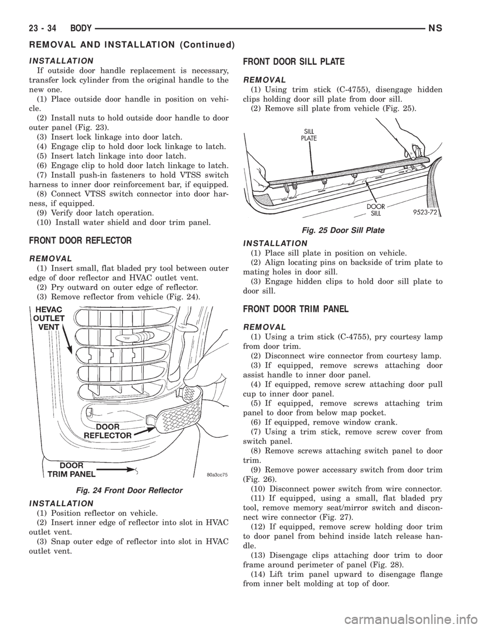
(3) Remove reflector from vehicle (Fig. 24).
INSTALLATION
(1) Position reflector on vehicle.
(2) Insert inner edge of reflector into slot in HVAC
outlet vent.
(3) Snap outer edge of reflector into slot in HVAC
outlet vent.
FRONT DOOR SILL PLATE
REMOVAL
(1) Using trim stick (C-4755), disengage hidden
clips holding door sill plate from door sill.
(2) Remove sill plate from vehicle (Fig. 25).
INSTALLATION
(1) Place sill plate in position on vehicle.
(2) Align locating pins on backside of trim plate to
mating holes in door sill.
(3) Engage hidden clips to hold door sill plate to
door sill.
FRONT DOOR TRIM PANEL
REMOVAL
(1) Using a trim stick (C-4755), pry courtesy lamp
from door trim.
(2) Disconnect wire connector from courtesy lamp.
(3) If equipped, remove screws attaching door
assist handle to inner door panel.
(4) If equipped, remove screw attaching door pull
cup to inner door panel.
(5) If equipped, remove screws attaching trim
panel to door from below map pocket.
(6) If equipped, remove window crank.
(7) Using a trim stick, remove screw cover from
switch panel.
(8) Remove screws attaching switch panel to door
trim.
(9) Remove power accessary switch from door trim
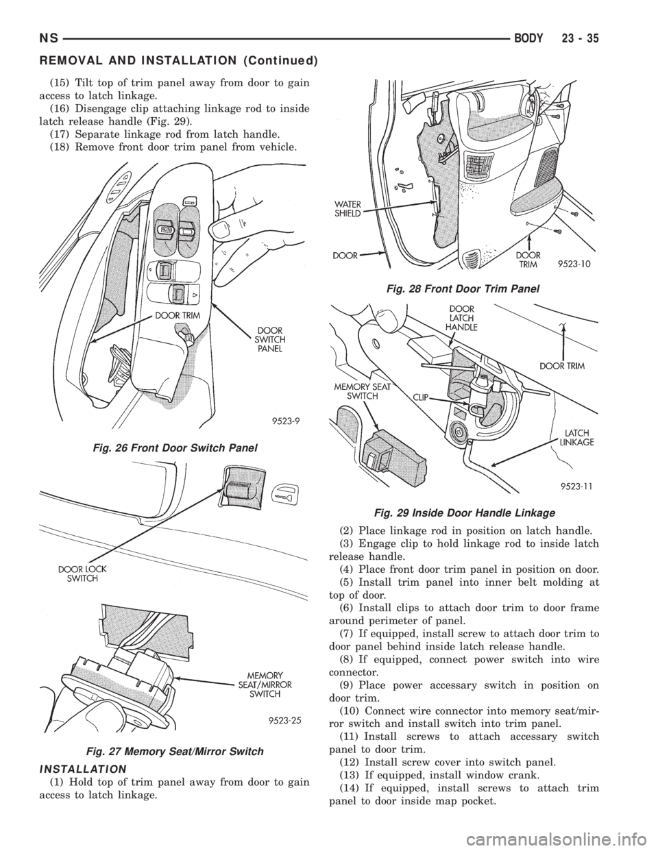
(Fig. 26).
(10) Disconnect power switch from wire connector.
(11) If equipped, using a small, flat bladed pry
tool, remove memory seat/mirror switch and discon-
nect wire connector (Fig. 27).
(12) If equipped, remove screw holding door trim
to door panel from behind inside latch release han-
dle.
(13) Disengage clips attaching door trim to door
frame around perimeter of panel (Fig. 28).
(14) Lift trim panel upward to disengage flange
from inner belt molding at top of door.
Fig. 24 Front Door Reflector
Fig. 25 Door Sill Plate
23 - 34 BODYNS
REMOVAL AND INSTALLATION (Continued)
Page 1765 of 1938
(15) Tilt top of trim panel away from door to gain
access to latch linkage.
(16) Disengage clip attaching linkage rod to inside
latch release handle (Fig. 29).
(17) Separate linkage rod from latch handle.
(18) Remove front door trim panel from vehicle.
INSTALLATION
(1) Hold top of trim panel away from door to gain
access to latch linkage.(2) Place linkage rod in position on latch handle.
(3) Engage clip to hold linkage rod to inside latch
release handle.
(4) Place front door trim panel in position on door.
(5) Install trim panel into inner belt molding at
top of door.
(6) Install clips to attach door trim to door frame
around perimeter of panel.
(7) If equipped, install screw to attach door trim to
door panel behind inside latch release handle.
(8) If equipped, connect power switch into wire
connector.
(9) Place power accessary switch in position on
door trim.
(10) Connect wire connector into memory seat/mir-
ror switch and install switch into trim panel.
(11) Install screws to attach accessary switch
panel to door trim.
(12) Install screw cover into switch panel.
(13) If equipped, install window crank.
(14) If equipped, install screws to attach trim
panel to door inside map pocket.
Fig. 26 Front Door Switch Panel
Fig. 27 Memory Seat/Mirror Switch
Fig. 28 Front Door Trim Panel
Fig. 29 Inside Door Handle Linkage
NSBODY 23 - 35
REMOVAL AND INSTALLATION (Continued)
Page 1766 of 1938
(15) If equipped, install screw to attach door pull
cup to inner door panel.
(16) If equipped, install screws to attach door
assist handle to inner door panel.
(17) Connect wire connector into courtesy lamp.
(18) Install lamp in door trim.
FRONT DOOR WEATHER-STRIP
REMOVAL
(1) Open front door.
(2) Using fork tool (C-4829), remove push-in fas-
teners holding front door weather-strip to end frames
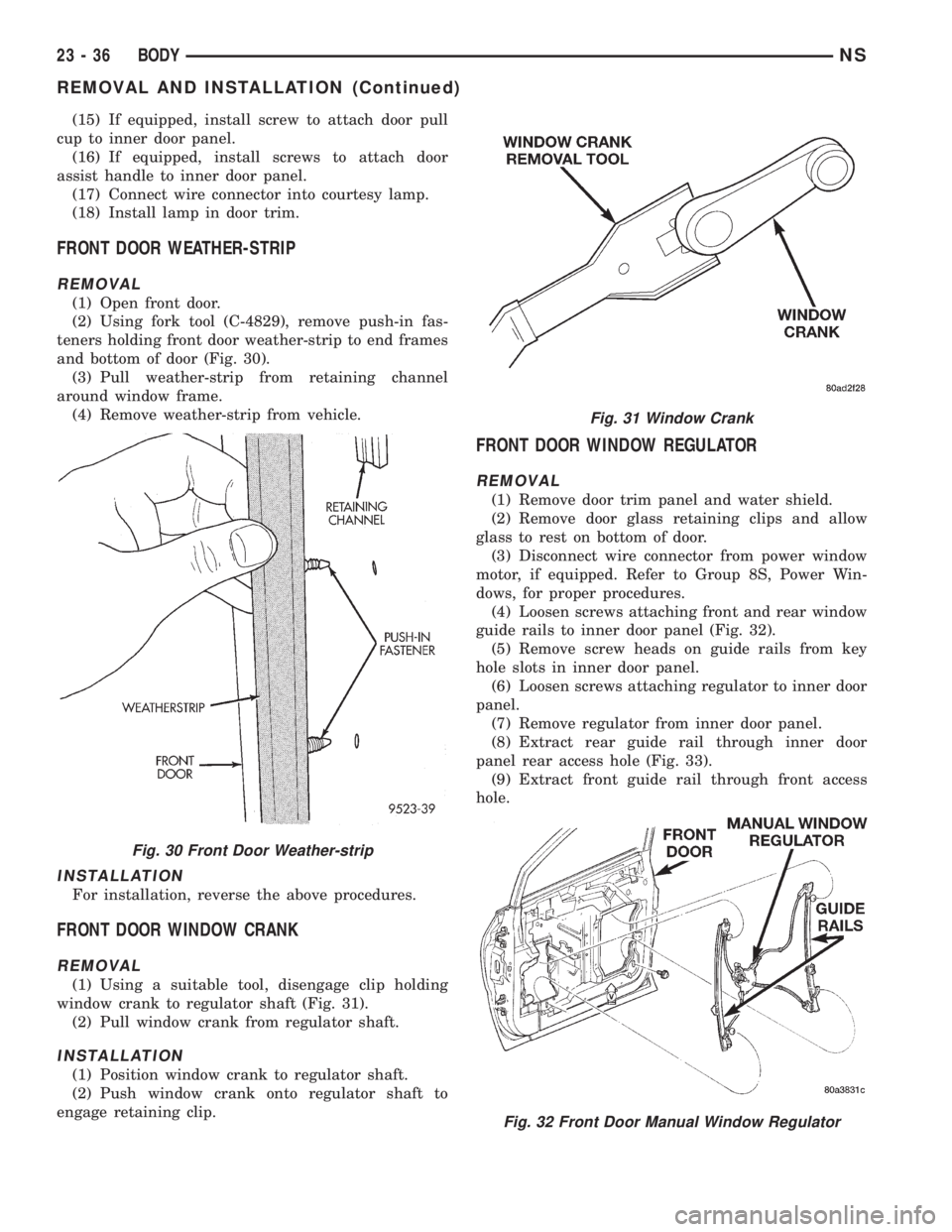
and bottom of door (Fig. 30).
(3) Pull weather-strip from retaining channel
around window frame.
(4) Remove weather-strip from vehicle.
INSTALLATION
For installation, reverse the above procedures.
FRONT DOOR WINDOW CRANK
REMOVAL
(1) Using a suitable tool, disengage clip holding
window crank to regulator shaft (Fig. 31).
(2) Pull window crank from regulator shaft.
INSTALLATION
(1) Position window crank to regulator shaft.
(2) Push window crank onto regulator shaft to
engage retaining clip.
FRONT DOOR WINDOW REGULATOR
REMOVAL
(1) Remove door trim panel and water shield.
(2) Remove door glass retaining clips and allow
glass to rest on bottom of door.
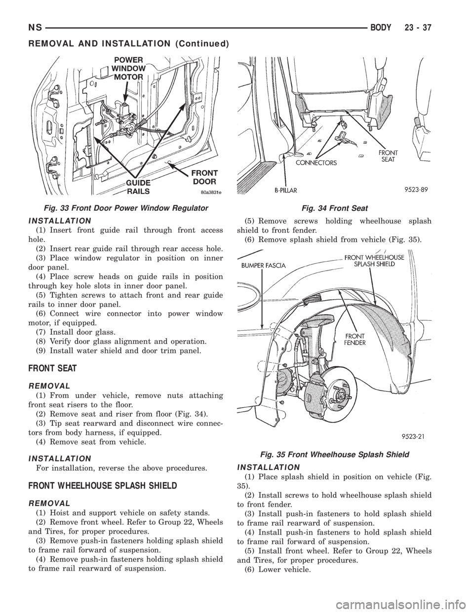
(3) Disconnect wire connector from power window
motor, if equipped. Refer to Group 8S, Power Win-
dows, for proper procedures.
(4) Loosen screws attaching front and rear window
guide rails to inner door panel (Fig. 32).
(5) Remove screw heads on guide rails from key
hole slots in inner door panel.
(6) Loosen screws attaching regulator to inner door
panel.
(7) Remove regulator from inner door panel.
(8) Extract rear guide rail through inner door
panel rear access hole (Fig. 33).
(9) Extract front guide rail through front access
hole.
Fig. 30 Front Door Weather-strip
Fig. 31 Window Crank
Fig. 32 Front Door Manual Window Regulator
23 - 36 BODYNS
REMOVAL AND INSTALLATION (Continued)
Page 1767 of 1938
INSTALLATION
(1) Insert front guide rail through front access
hole.
(2) Insert rear guide rail through rear access hole.
(3) Place window regulator in position on inner
door panel.
(4) Place screw heads on guide rails in position
through key hole slots in inner door panel.
(5) Tighten screws to attach front and rear guide
rails to inner door panel.
(6) Connect wire connector into power window
motor, if equipped.
(7) Install door glass.
(8) Verify door glass alignment and operation.
(9) Install water shield and door trim panel.
FRONT SEAT
REMOVAL
(1) From under vehicle, remove nuts attaching
front seat risers to the floor.
(2) Remove seat and riser from floor (Fig. 34).
(3) Tip seat rearward and disconnect wire connec-
tors from body harness, if equipped.
(4) Remove seat from vehicle.
INSTALLATION
For installation, reverse the above procedures.
FRONT WHEELHOUSE SPLASH SHIELD
REMOVAL
(1) Hoist and support vehicle on safety stands.
(2) Remove front wheel. Refer to Group 22, Wheels
and Tires, for proper procedures.
(3) Remove push-in fasteners holding splash shield
to frame rail forward of suspension.
(4) Remove push-in fasteners holding splash shield
to frame rail rearward of suspension.(5) Remove screws holding wheelhouse splash
shield to front fender.
(6) Remove splash shield from vehicle (Fig. 35).
INSTALLATION
(1) Place splash shield in position on vehicle (Fig.
35).
(2) Install screws to hold wheelhouse splash shield
to front fender.
(3) Install push-in fasteners to hold splash shield
to frame rail rearward of suspension.
(4) Install push-in fasteners to hold splash shield
to frame rail forward of suspension.
(5) Install front wheel. Refer to Group 22, Wheels
and Tires, for proper procedures.
(6) Lower vehicle.
Fig. 33 Front Door Power Window RegulatorFig. 34 Front Seat
Fig. 35 Front Wheelhouse Splash Shield
NSBODY 23 - 37
REMOVAL AND INSTALLATION (Continued)
Page 1776 of 1938
LIFTGATE
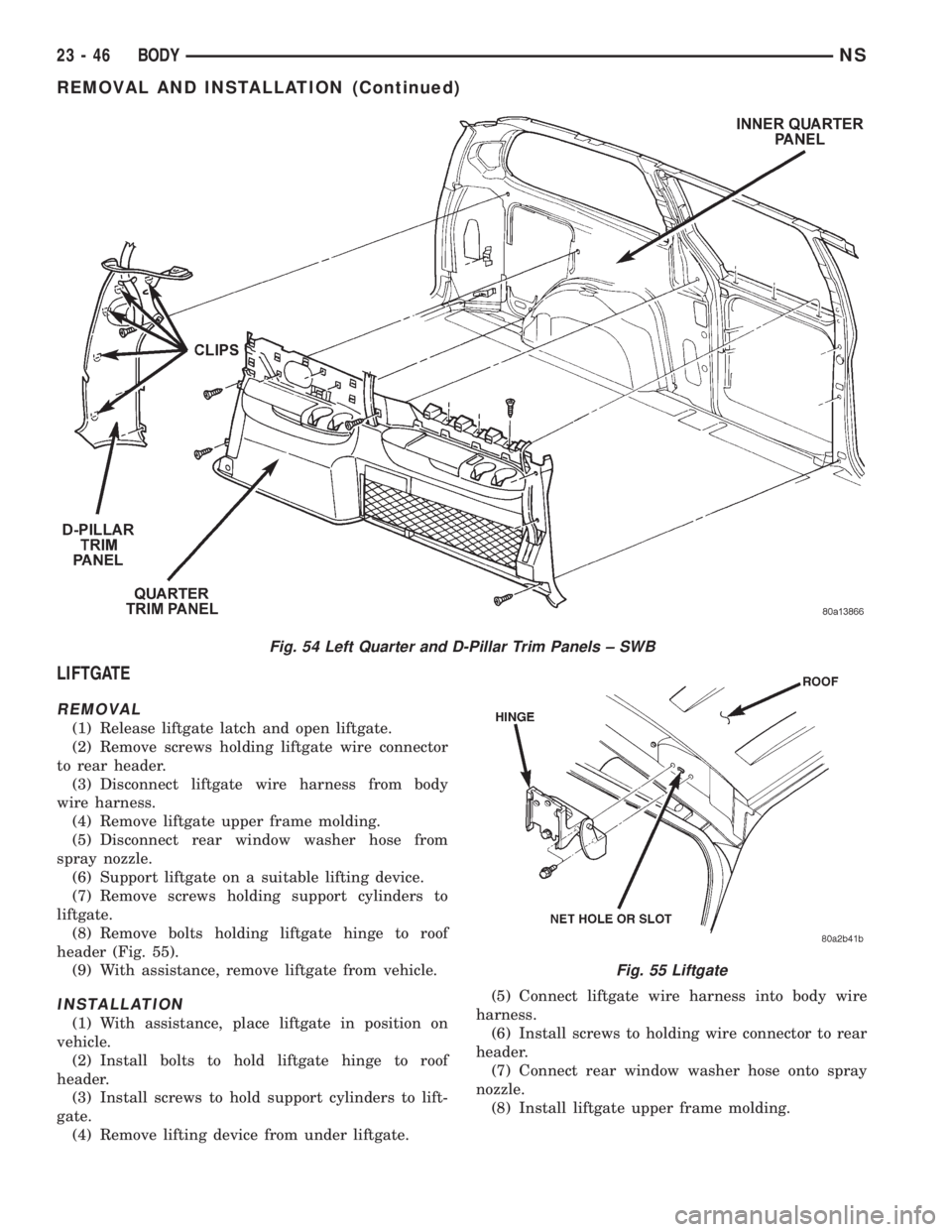
REMOVAL
(1) Release liftgate latch and open liftgate.
(2) Remove screws holding liftgate wire connector
to rear header.
(3) Disconnect liftgate wire harness from body
wire harness.
(4) Remove liftgate upper frame molding.
(5) Disconnect rear window washer hose from
spray nozzle.
(6) Support liftgate on a suitable lifting device.
(7) Remove screws holding support cylinders to
liftgate.
(8) Remove bolts holding liftgate hinge to roof
header (Fig. 55).
(9) With assistance, remove liftgate from vehicle.
INSTALLATION
(1) With assistance, place liftgate in position on
vehicle.
(2) Install bolts to hold liftgate hinge to roof
header.
(3) Install screws to hold support cylinders to lift-
gate.
(4) Remove lifting device from under liftgate.(5) Connect liftgate wire harness into body wire
harness.
(6) Install screws to holding wire connector to rear
header.
(7) Connect rear window washer hose onto spray
nozzle.
(8) Install liftgate upper frame molding.
Fig. 54 Left Quarter and D-Pillar Trim Panels ± SWB
Fig. 55 Liftgate
23 - 46 BODYNS
REMOVAL AND INSTALLATION (Continued)
Page 1782 of 1938
INSTALLATION
(1) Place crossbar in position on roof.
(2) Engage crossbar into notch in front riser.
(3) Slide crossbar rearward into desired position.
(4) Install luggage rack front riser covers.
LUGGAGE RACK RISER COVER
REMOVAL
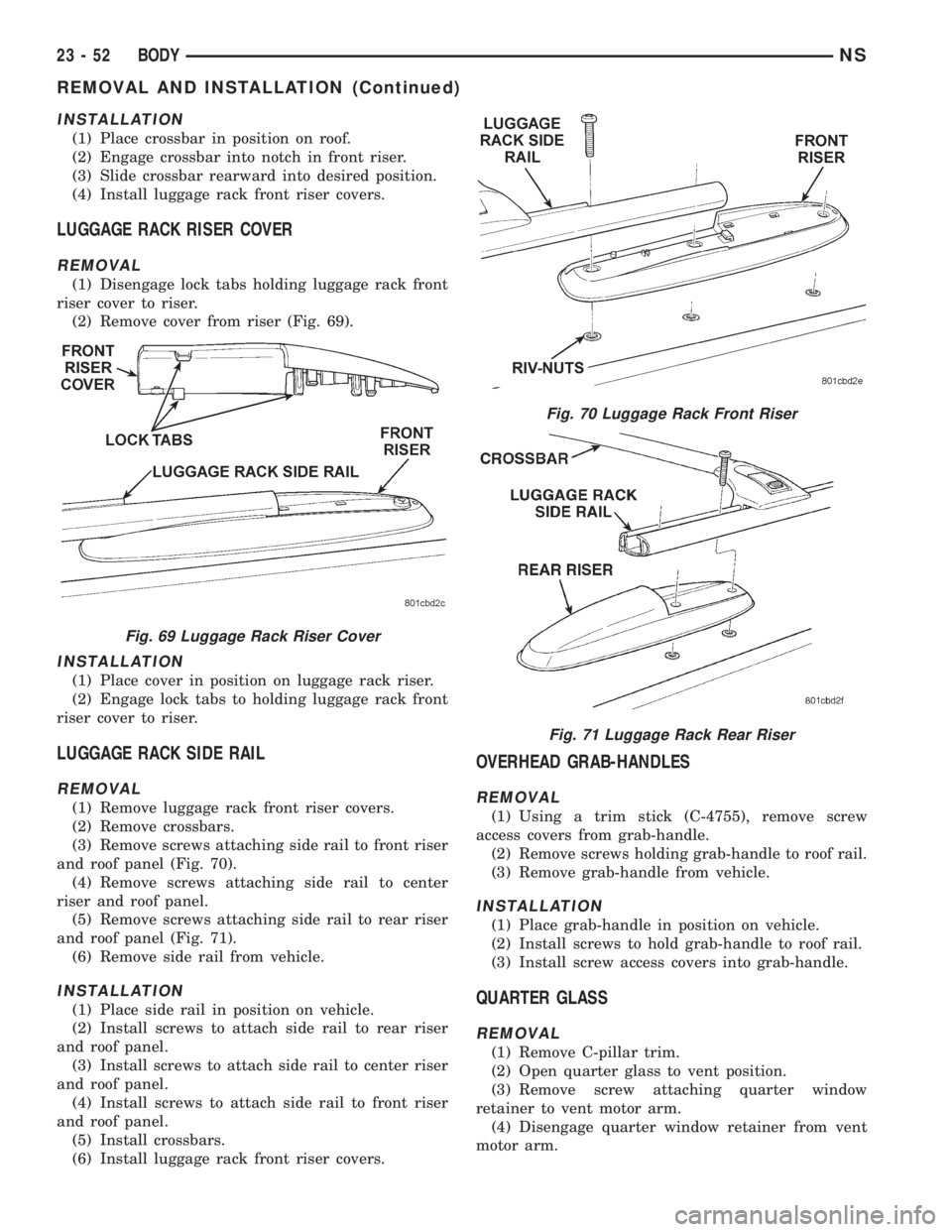
(1) Disengage lock tabs holding luggage rack front
riser cover to riser.
(2) Remove cover from riser (Fig. 69).
INSTALLATION
(1) Place cover in position on luggage rack riser.
(2) Engage lock tabs to holding luggage rack front
riser cover to riser.
LUGGAGE RACK SIDE RAIL
REMOVAL
(1) Remove luggage rack front riser covers.
(2) Remove crossbars.
(3) Remove screws attaching side rail to front riser
and roof panel (Fig. 70).
(4) Remove screws attaching side rail to center
riser and roof panel.
(5) Remove screws attaching side rail to rear riser
and roof panel (Fig. 71).
(6) Remove side rail from vehicle.
INSTALLATION
(1) Place side rail in position on vehicle.
(2) Install screws to attach side rail to rear riser
and roof panel.
(3) Install screws to attach side rail to center riser
and roof panel.
(4) Install screws to attach side rail to front riser
and roof panel.
(5) Install crossbars.
(6) Install luggage rack front riser covers.
OVERHEAD GRAB-HANDLES
REMOVAL
(1) Using a trim stick (C-4755), remove screw
access covers from grab-handle.
(2) Remove screws holding grab-handle to roof rail.
(3) Remove grab-handle from vehicle.
INSTALLATION
(1) Place grab-handle in position on vehicle.
(2) Install screws to hold grab-handle to roof rail.
(3) Install screw access covers into grab-handle.
QUARTER GLASS
REMOVAL
(1) Remove C-pillar trim.
(2) Open quarter glass to vent position.
(3) Remove screw attaching quarter window
retainer to vent motor arm.
(4) Disengage quarter window retainer from vent
motor arm.
Fig. 69 Luggage Rack Riser Cover
Fig. 70 Luggage Rack Front Riser
Fig. 71 Luggage Rack Rear Riser
23 - 52 BODYNS
REMOVAL AND INSTALLATION (Continued)
Page 1783 of 1938
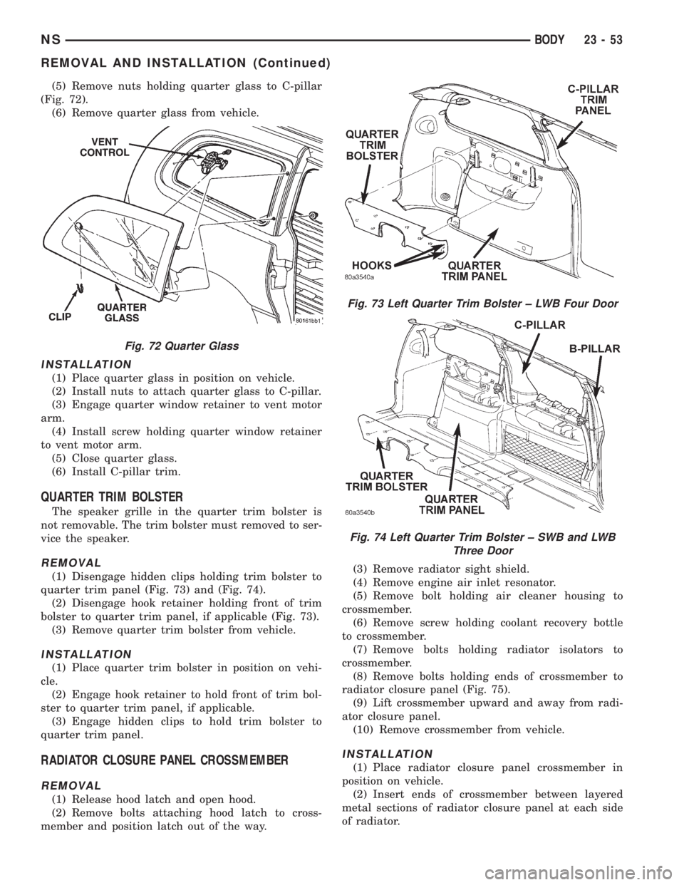
(5) Remove nuts holding quarter glass to C-pillar
(Fig. 72).
(6) Remove quarter glass from vehicle.
INSTALLATION
(1) Place quarter glass in position on vehicle.
(2) Install nuts to attach quarter glass to C-pillar.
(3) Engage quarter window retainer to vent motor
arm.
(4) Install screw holding quarter window retainer
to vent motor arm.
(5) Close quarter glass.
(6) Install C-pillar trim.
QUARTER TRIM BOLSTER
The speaker grille in the quarter trim bolster is
not removable. The trim bolster must removed to ser-
vice the speaker.
REMOVAL
(1) Disengage hidden clips holding trim bolster to
quarter trim panel (Fig. 73) and (Fig. 74).
(2) Disengage hook retainer holding front of trim
bolster to quarter trim panel, if applicable (Fig. 73).
(3) Remove quarter trim bolster from vehicle.
INSTALLATION
(1) Place quarter trim bolster in position on vehi-
cle.
(2) Engage hook retainer to hold front of trim bol-
ster to quarter trim panel, if applicable.
(3) Engage hidden clips to hold trim bolster to
quarter trim panel.
RADIATOR CLOSURE PANEL CROSSMEMBER
REMOVAL
(1) Release hood latch and open hood.
(2) Remove bolts attaching hood latch to cross-
member and position latch out of the way.(3) Remove radiator sight shield.
(4) Remove engine air inlet resonator.
(5) Remove bolt holding air cleaner housing to
crossmember.
(6) Remove screw holding coolant recovery bottle
to crossmember.
(7) Remove bolts holding radiator isolators to
crossmember.
(8) Remove bolts holding ends of crossmember to
radiator closure panel (Fig. 75).
(9) Lift crossmember upward and away from radi-
ator closure panel.
(10) Remove crossmember from vehicle.
INSTALLATION
(1) Place radiator closure panel crossmember in
position on vehicle.
(2) Insert ends of crossmember between layered
metal sections of radiator closure panel at each side
of radiator.
Fig. 72 Quarter Glass
Fig. 73 Left Quarter Trim Bolster ± LWB Four Door
Fig. 74 Left Quarter Trim Bolster ± SWB and LWB
Three Door
NSBODY 23 - 53
REMOVAL AND INSTALLATION (Continued)
Page 1817 of 1938

HEATING AND AIR CONDITIONING
CONTENTS
page page
FRONT HEATING AND AIR CONDITIONING
SYSTEM............................... 1REAR HEATING AND AIR CONDITIONING
SYSTEM.............................. 41
FRONT HEATING AND AIR CONDITIONING SYSTEM
INDEX
page page
GENERAL INFORMATION
INTRODUCTION......................... 2
SAFETY PRECAUTIONS AND WARNINGS...... 2
DESCRIPTION AND OPERATION
A/C PRESSURE TRANSDUCER.............. 2
A/C SERVICE PORTS..................... 2
AIR DISTRIBUTION DUCTS................. 2
COMPRESSOR HIGH-PRESSURE RELIEF
VALVE................................ 3
CONDENSATE DRAIN..................... 3
ENGINE COOLING SYSTEM REQUIREMENTS . . 3
EVAPORATOR PROBE..................... 3
HANDLING TUBING AND FITTINGS........... 3
HVAC CONTROL MODULE................. 4
REAR BLOWER SPEED SWITCH............ 3
SIDE DOOR HEATER A/C OUTLETS.......... 4
SIDE WINDOW DEMISTER................. 4
SYSTEM AIRFLOW....................... 4
SYSTEM OIL LEVEL...................... 5
DIAGNOSIS AND TESTING
A/C PERFORMANCE TEST................ 12
A/C PRESSURE TRANSDUCER............. 12
ACTUATOR CALIBRATION/DIAGNOSTICS AND
COOLDOWN TEST...................... 6
BLOWER MOTOR AND WHEEL ASSEMBLY.... 13
COMPRESSOR CLUTCH/COIL.............. 13
COMPRESSOR NOISE DIAGNOSIS.......... 13
EXPANSION VALVE...................... 13
HEATER PERFORMANCE TEST............ 15
HVAC CONTROL DIAGNOSTIC CONDITIONS . . . 9
SYSTEM CHARGE LEVEL TEST............ 16SERVICE PROCEDURES
CHARGING REFRIGERANT SYSTEM........ 17
EVACUATING REFRIGERANT SYSTEM....... 18
R-134a REFRIGERANT................... 16
STICKING HVAC CONTROL MODULE PUSH
BUTTONS............................ 19
SYSTEM LEAK CHECKING................ 19
THERMOCOUPLE PROBE................. 19
REMOVAL AND INSTALLATION
A/C PRESSURE TRANSDUCER............. 20
A/C SERVICE PORTS.................... 20
BLEND-AIR DOOR ACTUATOR............. 20
BLOWER MOTOR AND WHEEL ASSEMBLY.... 21
BLOWER MOTOR RESISTOR BLOCK........ 21
BLOWER MOTOR WHEEL................. 22
COMPRESSOR CLUTCH/COIL.............. 23
COMPRESSOR......................... 23
CONDENSER ASSEMBLY................. 25
DISCHARGE LINE....................... 26
EVAPORATOR PROBE.................... 27
EXPANSION VALVE...................... 28
FILTER-DRIER ASSEMBLY................. 28
HEATER A/C UNIT HOUSING............... 29
HEATER CORE......................... 30
HEATER HOSES........................ 31
LIQUID LINE........................... 32
MODE DOOR ACTUATOR................. 32
RECIRC DOOR ACTUATOR................ 34
SIDE WINDOW DEMISTER DUCTS.......... 33
SUCTION LINE.......................... 33
DISASSEMBLY AND ASSEMBLY
HEATER A/C UNIT RECONDITION........... 34
NSHEATING AND AIR CONDITIONING 24 - 1
Page 1818 of 1938
GENERAL INFORMATION
INTRODUCTION
Both the heater and the heater/air conditioning
systems share many of the same components. This
group will deal with both systems together when
component function is common, and separately when
they are not.
For proper operation of the instrument panel con-
trols, refer to the Owner's Manual provided with the
vehicle.
All vehicles are equipped with a common A/C-
heater unit housing assembly. When the vehicle has
only a heater system, the evaporator and recirculat-
ing air door are omitted.
An optional zone control HVAC unit is available.
This unit has dual blend-air doors that can be regu-
lated independently of each other. The temperature
setting can be different from driver's side to passen-
ger side. There is also a rear (aux.) heating and A/C
system available when the vehicle is equipped with
zone control.
SAFETY PRECAUTIONS AND WARNINGS
WARNING: WEAR EYE PROTECTION WHEN SER-
VICING THE AIR CONDITIONING REFRIGERANT
SYSTEM. SERIOUS EYE INJURY CAN RESULT
FROM EYE CONTACT WITH REFRIGERANT. IF EYE
CONTACT IS MADE, SEEK MEDICAL ATTENTION
IMMEDIATELY.
DO NOT EXPOSE REFRIGERANT TO OPEN
FLAME. POISONOUS GAS IS CREATED WHEN
REFRIGERANT IS BURNED. AN ELECTRONIC TYPE
LEAK DETECTOR IS RECOMMENDED.
LARGE AMOUNTS OF REFRIGERANT RELEASED
IN A CLOSED WORK AREA WILL DISPLACE THE
OXYGEN AND CAUSE SUFFOCATION.
THE EVAPORATION RATE OF REFRIGERANT AT
AVERAGE TEMPERATURE AND ALTITUDE IS
EXTREMELY HIGH. AS A RESULT, ANYTHING THAT
COMES IN CONTACT WITH THE REFRIGERANT
WILL FREEZE. ALWAYS PROTECT SKIN OR DELI-
CATE OBJECTS FROM DIRECT CONTACT WITH
REFRIGERANT. R-134a SERVICE EQUIPMENT OR
VEHICLE A/C SYSTEM SHOULD NOT BE PRES-
SURE TESTED OR LEAK TESTED WITH COM-
PRESSED AIR.
SOME MIXTURES OF AIR and R-134a HAVE BEEN
SHOWN TO BE COMBUSTIBLE AT ELEVATED
PRESSURES. THESE MIXTURES ARE POTENTIALLY
DANGEROUS AND MAY RESULT IN FIRE OR
EXPLOSION CAUSING INJURY OR PROPERTY
DAMAGE.
ANTIFREEZE IS AN ETHYLENE GLYCOL BASE
COOLANT AND IS HARMFUL IF SWALLOWED ORINHALED. SEEK MEDICAL ATTENTION IMMEDI-
ATELY IF SWALLOWED OR INHALED. DO NOT
STORE IN OPEN OR UNMARKED CONTAINERS.
WASH SKIN AND CLOTHING THOROUGHLY AFTER
COMING IN CONTACT WITH ETHYLENE GLYCOL.
KEEP OUT OF REACH OF CHILDREN AND PETS.
DO NOT OPEN A COOLING SYSTEM WHEN THE
ENGINE IS AT RUNNING TEMPERATURE. PER-
SONAL INJURY CAN RESULT.
CAUTION: The engine cooling system is designed
to develop internal pressure of 97 to 123 kPa (14 to
18 psi). Allow the vehicle to cool a minimum of 15
minutes before opening the cooling system. Refer
to Group 7, Cooling System.
DESCRIPTION AND OPERATION
AIR DISTRIBUTION DUCTS
The air distribution ducts for the A/C, Heater,
Defroster, and Second Seating Air Distribution are
not serviceable in vehicle. The procedures for service
of these ducts are covered in Group 8E, Instrument
Panel and Gauges.
The only ducts that are serviceable in the vehicle
are the side window demister ducts and the ducts
that feed the front door outlets for the first rear pas-
senger(s) seating. To service the door ducts refer to
Group 23, Body.
A/C PRESSURE TRANSDUCER
The A/C Pressure Transducer (Fig. 1) monitors the
refrigerant gas pressure on the high side of the sys-
tem. The transducer is located on the liquid line. The
pressure transducer turns off the voltage to the com-
pressor clutch coil when refrigerant gas pressure
drops to levels that could damage the compressor.
The transducer also is used to adjust condenser fan
speeds and will turn off compressor at high refriger-
ant pressures. The pressure transducer is a sealed
factory calibrated unit. It must be replaced if defec-
tive. O-ring replacement is required whenever the
pressure transducer is serviced. Be sure to use the
O-ring specified for the transducer.
A/C SERVICE PORTS
The A/C service port valve cores are located within
the A/C lines (Fig. 2). The High Side (Discharge)
valve service port is located on the liquid line near
the right frame rail. The Low Side (Suction) valve
service port is located on the suction line near the
compressor.
24 - 2 HEATING AND AIR CONDITIONINGNS