window CHRYSLER VOYAGER 1996 Repair Manual
[x] Cancel search | Manufacturer: CHRYSLER, Model Year: 1996, Model line: VOYAGER, Model: CHRYSLER VOYAGER 1996Pages: 1938, PDF Size: 55.84 MB
Page 969 of 1938
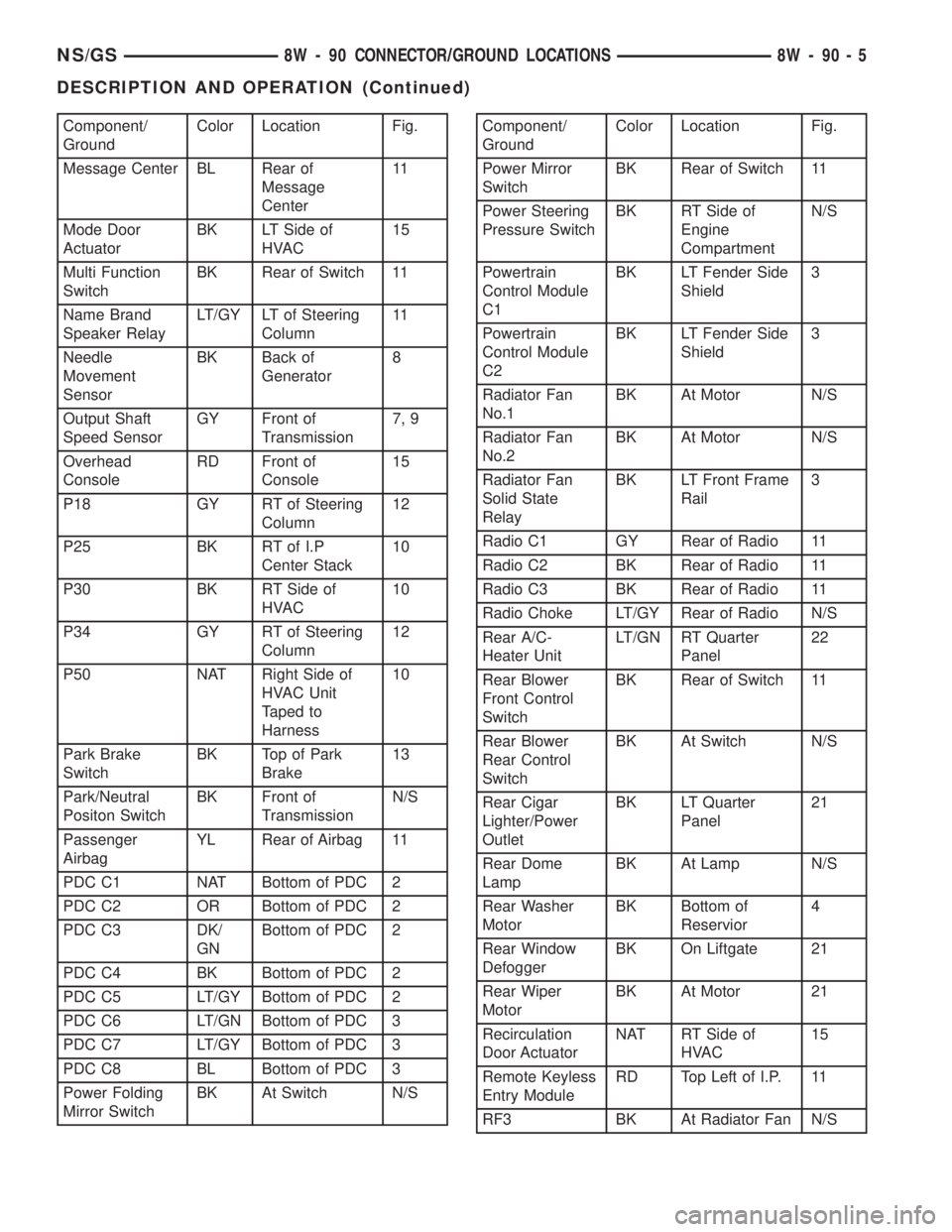
Component/
GroundColor Location Fig.
Message Center BL Rear of
Message
Center11
Mode Door
ActuatorBK LT Side of
HVAC15
Multi Function
SwitchBK Rear of Switch 11
Name Brand
Speaker RelayLT/GY LT of Steering
Column11
Needle
Movement
SensorBK Back of
Generator8
Output Shaft
Speed SensorGY Front of
Transmission7, 9
Overhead
ConsoleRD Front of
Console15
P18 GY RT of Steering
Column12
P25 BK RT of I.P
Center Stack10
P30 BK RT Side of
HVAC10
P34 GY RT of Steering
Column12
P50 NAT Right Side of
HVAC Unit
Taped to
Harness10
Park Brake
SwitchBK Top of Park
Brake13
Park/Neutral
Positon SwitchBK Front of
TransmissionN/S
Passenger
AirbagYL Rear of Airbag 11
PDC C1 NAT Bottom of PDC 2
PDC C2 OR Bottom of PDC 2
PDC C3 DK/
GNBottom of PDC 2
PDC C4 BK Bottom of PDC 2
PDC C5 LT/GY Bottom of PDC 2
PDC C6 LT/GN Bottom of PDC 3
PDC C7 LT/GY Bottom of PDC 3
PDC C8 BL Bottom of PDC 3
Power Folding
Mirror SwitchBK At Switch N/SComponent/
GroundColor Location Fig.
Power Mirror
SwitchBK Rear of Switch 11
Power Steering
Pressure SwitchBK RT Side of
Engine
CompartmentN/S
Powertrain
Control Module
C1BK LT Fender Side
Shield3
Powertrain
Control Module
C2BK LT Fender Side
Shield3
Radiator Fan
No.1BK At Motor N/S
Radiator Fan
No.2BK At Motor N/S
Radiator Fan
Solid State
RelayBK LT Front Frame
Rail3
Radio C1 GY Rear of Radio 11
Radio C2 BK Rear of Radio 11
Radio C3 BK Rear of Radio 11
Radio Choke LT/GY Rear of Radio N/S
Rear A/C-
Heater UnitLT/GN RT Quarter
Panel22
Rear Blower
Front Control
SwitchBK Rear of Switch 11
Rear Blower
Rear Control
SwitchBK At Switch N/S
Rear Cigar
Lighter/Power
OutletBK LT Quarter
Panel21
Rear Dome
LampBK At Lamp N/S
Rear Washer
MotorBK Bottom of
Reservior4
Rear Window
DefoggerBK On Liftgate 21
Rear Wiper
MotorBK At Motor 21
Recirculation
Door ActuatorNAT RT Side of
HVAC15
Remote Keyless
Entry ModuleRD Top Left of I.P. 11
RF3 BK At Radiator Fan N/S
NS/GS8W - 90 CONNECTOR/GROUND LOCATIONS 8W - 90 - 5
DESCRIPTION AND OPERATION (Continued)
Page 970 of 1938
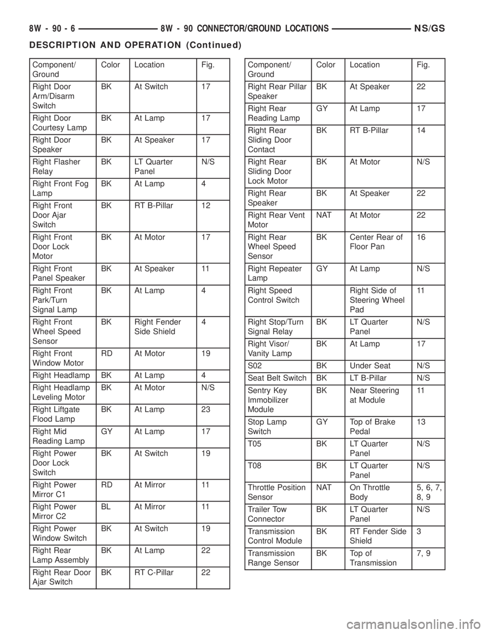
Component/
GroundColor Location Fig.
Right Door
Arm/Disarm
SwitchBK At Switch 17
Right Door
Courtesy LampBK At Lamp 17
Right Door
SpeakerBK At Speaker 17
Right Flasher
RelayBK LT Quarter
PanelN/S
Right Front Fog
LampBK At Lamp 4
Right Front
Door Ajar
SwitchBK RT B-Pillar 12
Right Front
Door Lock
MotorBK At Motor 17
Right Front
Panel SpeakerBK At Speaker 11
Right Front
Park/Turn
Signal LampBK At Lamp 4
Right Front
Wheel Speed
SensorBK Right Fender
Side Shield4
Right Front
Window MotorRD At Motor 19
Right Headlamp BK At Lamp 4
Right Headlamp
Leveling MotorBK At Motor N/S
Right Liftgate
Flood LampBK At Lamp 23
Right Mid
Reading LampGY At Lamp 17
Right Power
Door Lock
SwitchBK At Switch 19
Right Power
Mirror C1RD At Mirror 11
Right Power
Mirror C2BL At Mirror 11
Right Power
Window SwitchBK At Switch 19
Right Rear
Lamp AssemblyBK At Lamp 22
Right Rear Door
Ajar SwitchBK RT C-Pillar 22Component/
GroundColor Location Fig.
Right Rear Pillar
SpeakerBK At Speaker 22
Right Rear
Reading LampGY At Lamp 17
Right Rear
Sliding Door
ContactBK RT B-Pillar 14
Right Rear
Sliding Door
Lock MotorBK At Motor N/S
Right Rear
SpeakerBK At Speaker 22
Right Rear Vent
MotorNAT At Motor 22
Right Rear
Wheel Speed
SensorBK Center Rear of
Floor Pan16
Right Repeater
LampGY At Lamp N/S
Right Speed
Control SwitchRight Side of
Steering Wheel
Pad11
Right Stop/Turn
Signal RelayBK LT Quarter
PanelN/S
Right Visor/
Vanity LampBK At Lamp 17
S02 BK Under Seat N/S
Seat Belt Switch BK LT B-Pillar N/S
Sentry Key
Immobilizer
ModuleBK Near Steering
at Module11
Stop Lamp
SwitchGY Top of Brake
Pedal13
T05 BK LT Quarter
PanelN/S
T08 BK LT Quarter
PanelN/S
Throttle Position
SensorNAT On Throttle
Body5, 6, 7,
8, 9
Trailer Tow
ConnectorBK LT Quarter
PanelN/S
Transmission
Control ModuleBK RT Fender Side
Shield3
Transmission
Range SensorBK Top of
Transmission7, 9
8W - 90 - 6 8W - 90 CONNECTOR/GROUND LOCATIONSNS/GS
DESCRIPTION AND OPERATION (Continued)
Page 997 of 1938

Component/
GroundColor Location Fig.
Headlamp
Switch C1NAT Rear of Switch 11
Headlamp
Switch C2BK Rear of Switch 11
Headlamp
Washer MotorBottom of
ReserviorN/S
High Note Horn BK LT Frame Rail 4
Hood Ajar
SwitchNAT LT Fender 2
Horn Switch Rear of Driver
Airbag11
Idle Air Control
MotorBK On Throttle
Body5, 6, 7,
8, 9
Ignition Coil
Pack 2.4LBK Top of Valve
Cover6, 7
Ignition Coil
Pack 3.3L, 3.8LBK RT Side of
Engine9
Ignition Switch
C1GY Rear of Switch 11
Ignition Switch
C2GN Rear of Switch 11
Ignition Switch
C3BK Rear of Switch 11
Instrument
ClusterRD Rear of Cluster 11
Intake Air Temp
SensorGY On Intake 6, 7
J01D BK RT Side of
HVAC15
J02A BK Top of Liftgate 23
JO3A BK Top of Liftgate 23
Junction Block
C1GY On Junction
Block12, 13
Junction Block
C2GY On Junction
Block12, 13
Junction Block
C3GY On Junction
Block12
Junction Block
C4GY On Junction
Block12
Key-In Halo
LampWT Rear of Lamp 11
Knock Sensor
2.4LGY Front of
Cylinder Block6, 7
Knock Sensor
3.3L, 3.8LGY Front of
Cylinder BlockN/S
L15 BK Top of Liftgate 23Component/
GroundColor Location Fig.
L16 BK Top of Liftgate 23
Left
Combination
RelayBK LT Rear
Quarter PanelN/S
Left Door Ajar
SwitchBK LT B-PIllar 12
Left Door
Arm/Disarm
SwitchBK At Switch 19
Left Door
Courtesy LampBK At Lamp 19
Left Door
SpeakerBK At Speaker 19
Left Fog Lamp GY At Lamp 4
Left Front Door
Lock MotorBK At Motor 19
Left Front Panel
SpeakerBK At Speaker 11
Left Front
Park/Turn
Signal LampBK At Lamp 4
Left Front
Wheel Speed
SensorBK LT Fender Side
Shield2
Left Front
Window MotorRD At Motor 19
Left Headlamp BK At Lamp 2
Left Headlamp
Leveling MotorBK At Motor N/S
Left Liftgate
Flood LampBK At Lamp 23
Left Mid
Reading LampGY At Lamp 17
Left Power Door
Lock SwitchBK At Switch 19
Left Power
Mirror C1RD At Mirror 11
Left Power
Mirror C2BL At Mirror 11
Left Power
Window SwitchOR At Switch 19
Left Rear Lamp
AssemblyBK At Lamp 21
Left Rear Door
Ajar SwitchBK LT C-Pillar 21
Left Rear Pillar
SpeakerBK At Speaker 21
NS/GS8W - 90 CONNECTOR/GROUND LOCATIONS 8W - 90 - 33
DESCRIPTION AND OPERATION (Continued)
Page 999 of 1938

Component/
GroundColor Location Fig.
Powertrain
Control Module
C1BK LT Fender Side
Shield3
Powertrain
Control Module
C2BK LT Fender Side
Shield3
Radiator Fan
No.1BK At Motor N/S
Radiator Fan
No.2BK At Motor N/S
Radiator Fan
RelayBK LT Front Frame
Rail3
Radio C1 GY Rear of Radio 11
Radio C2 BK Rear of Radio 11
Radio C3 BK Rear of Radio 11
Radio Choke LT/GY Rear of Radio N/S
Rear A/C-
Heater UnitLT/GN RT Quarter
Panel22
Rear Blower
Front Control
SwitchBK Rear of Switch 11
Rear Blower
Rear Control
SwitchBK At Switch N/S
Rear Cigar
Lighter/Power
OutletBK LT Quarter
Panel21
Rear Dome
LampBK At Lamp N/S
Rear Washer
MotorBK Bottom of
Reservior4
Rear Window
DefoggerBK On Liftgate 23
Rear Wiper
MotorBK At Motor 23
Recirculation
Door ActuatorNAT RT Side of
HVAC15
Remote Keyless
Entry ModuleRD Top RT of I.P. 11
Right
Combination
RelayBK LT Quarter
PanelN/S
Right Door
Arm/Disarm
SwitchBK At Switch 19
Right Door
Courtesy LampBK At Lamp 19Component/
GroundColor Location Fig.
Right Door
SpeakerBK At Speaker 19
RF3 BK At Radiator Fan
ModuleN/S
Right Fog Lamp GY At Lamp 4
Right Front
Door Ajar
SwitchBK RT B-Pillar 12
Right Front
Door Lock
MotorBK At Motor 19
Right Front
Panel SpeakerBK At Speaker 11
Right Front
Park/Turn
Signal LampBK At Lamp 4
Right Front
Wheel Speed
SensorBK Right Fender
Side Shield4
Right Front
Window MotorRD At Motor 19
Right Headlamp BK At Lamp 4
Right Headlamp
Leveling MotorBK At Motor N/S
Right Liftgate
Flood LampBK At Lamp 23
Right Mid
Reading LampGY At Lamp 17
Right Power
Door Lock
SwitchBK At Switch 19
Right Power
Mirror C1RD At Mirror 11
Right Power
Mirror C2BL At Mirror 11
Right Power
Window SwitchBK At Switch 19
Right Rear
Lamp AssemblyBK At Lamp 22
Right Rear Door
Ajar SwitchBK RT C-Pillar N/S
Right Rear Pillar
SpeakerBK At Speaker 22
Right Rear
Reading LampGY At Lamp 17
NS/GS8W - 90 CONNECTOR/GROUND LOCATIONS 8W - 90 - 35
DESCRIPTION AND OPERATION (Continued)
Page 1306 of 1938
(9) Momentarily touch the other end of this
jumper wire to the negative terminal of the battery
for no more than 4 seconds.
(10) Place a rag or towel below the fuel line at the
quick connect to the rail.
(11) Disconnect the quick connect fitting to the
rail. Refer to Quick-Connect Fittings in this section.
(12) Return the fuel pump relay to the PDC.
(13) One or more Diagnostic Trouble Codes (DTC's)
may have been stored in the PCM memory due to the
fuel pump relay removal. The DRB scan tool must be
used to erase a DTC. Refer to group 25, On-Board
Diagnostics.
HOSES AND CLAMPS
Inspect all hose connections (clamps and quick con-
nect fittings) for completeness and leaks. Replace
cracked, scuffed, or swelled hoses. Replace hoses that
rub against other vehicle components or show sign of
wear.
Fuel injected vehicles use specially constructed
hoses. When replacing hoses, only use hoses marked
EFM/EFI.
When installing hoses, ensure that they are routed
away from contact with other vehicle components
that could rub against them and cause failure. Avoid
contact with clamps or other components that cause
abrasions or scuffing. Ensure that rubber hoses are
properly routed and avoid heat sources.
The hose clamps have rolled edges to prevent the
clamp from cutting into the hose. Only use clamps
that are original equipment or equivalent. Other
types of clamps may cut into the hoses and cause
high pressure fuel leaks. Tighten hose clamps to 1
N´m (10 in. lbs.) torque.
QUICK-CONNECT FITTINGS
REMOVAL
When disconnecting a quick-connect fitting, the
retainer will remain on the fuel tube nipple.
WARNING: RELEASE FUEL SYSTEM PRESSURE
BEFORE DISCONNECTING A QUICK-CONNECT FIT-
TINGS. REFER TO THE FUEL PRESSURE RELEASE
PROCEDURE.
(1) Disconnect negative cable from battery.
(2) Perform Fuel Pressure Release Procedure.
Refer to the Fuel Pressure Release Procedure in this
section.
(3) Squeeze retainer tabs together and pull fuel
tube/quick-connect fitting assembly off of fuel tube
nipple. The retainer will remain on fuel tube.
INSTALLATION
CAUTION: Never install a quick-connect fitting
without the retainer being either on the fuel tube or
already in the quick-connect fitting. In either case,
ensure the retainer locks securely into the quick-
connect fitting by firmly pulling on fuel tube and fit-
ting to ensure it is secured.
(1) Using a clean lint free cloth, clean the fuel tube
nipple and retainer.
(2) Prior to connecting the fitting to the fuel tube,
coat the fuel tube nipple with clean 30 weight engine
oil.
(3) Push the quick-connect fitting over the fuel
tube until theretainer seats and a click is heard.
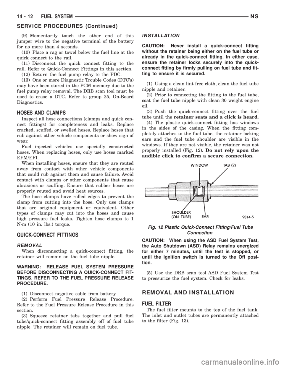
(4) The plastic quick-connect fitting has windows
in the sides of the casing. When the fitting com-
pletely attaches to the fuel tube, the retainer locking
ears and the fuel tube shoulder are visible in the
windows. If they are not visible, the retainer was not
properly installed (Fig. 12).Do not rely upon the
audible click to confirm a secure connection.
CAUTION: When using the ASD Fuel System Test,
the Auto Shutdown (ASD) Relay remains energized
for either 7 minutes, until the test is stopped, or
until the ignition switch is turned to the Off posi-
tion.
(5) Use the DRB scan tool ASD Fuel System Test
to pressurize the fuel system. Check for leaks.
REMOVAL AND INSTALLATION
FUEL FILTER
The fuel filter mounts to the top of the fuel tank.
The inlet and outlet tubes are permanently attached
to the filter (Fig. 13).
Fig. 12 Plastic Quick-Connect Fitting/Fuel Tube
Connection
14 - 12 FUEL SYSTEMNS
SERVICE PROCEDURES (Continued)
Page 1734 of 1938

STATIONARY GLASS
INDEX
page page
DESCRIPTION AND OPERATION
SAFETY PRECAUTIONS................... 4
REMOVAL AND INSTALLATION
BODY SIDE/SLIDING DOOR STATIONARY
GLASS............................... 6REAR WINDOW.......................... 7
WINDSHIELD............................ 4
DESCRIPTION AND OPERATION
SAFETY PRECAUTIONS
WARNING: DO NOT OPERATE THE VEHICLE
WITHIN 24 HOURS OF WINDSHIELD INSTALLATION.
IT TAKES AT LEAST 24 HOURS FOR URETHANE
ADHESIVE TO CURE. IF IT IS NOT CURED, THE
WINDSHIELD MAY NOT PERFORM PROPERLY IN
AN ACCIDENT.
URETHANE ADHESIVES ARE APPLIED AS A SYS-
TEM. USE GLASS CLEANER, GLASS PREP SOL-
VENT, GLASS PRIMER, PVC (VINYL) PRIMER AND
PINCHWELD (FENCE) PRIMER PROVIDED BY THE
ADHESIVE MANUFACTURER. IF NOT, STRUCTURAL
INTEGRITY COULD BE COMPROMISED.
CHRYSLER DOES NOT RECOMMEND GLASS
ADHESIVE BY BRAND. TECHNICIANS SHOULD
REVIEW PRODUCT LABELS AND TECHNICAL DATA
SHEETS, AND USE ONLY ADHESIVES THAT THEIR
MANUFACTURES WARRANT WILL RESTORE A
VEHICLE TO THE REQUIREMENTS OF FMVSS 212.
TECHNICIANS SHOULD ALSO INSURE THAT PRIM-
ERS AND CLEANERS ARE COMPATIBLE WITH THE
PARTICULAR ADHESIVE USED.
BE SURE TO REFER TO THE URETHANE MANU-
FACTURER'S DIRECTIONS FOR CURING TIME
SPECIFICATIONS, AND DO NOT USE ADHESIVE
AFTER ITS EXPIRATION DATE.
VAPORS THAT ARE EMITTED FROM THE URE-
THANE ADHESIVE OR PRIMER COULD CAUSE
PERSONAL INJURY. USE THEM IN A WELL-VENTI-
LATED AREA.
SKIN CONTACT WITH URETHANE ADHESIVE
SHOULD BE AVOIDED. PERSONAL INJURY MAY
RESULT.
ALWAYS WEAR EYE AND HAND PROTECTION
WHEN WORKING WITH GLASS.
CAUTION: Protect all painted and trimmed surfaces
from coming in contact with urethane or primers.Be careful not to damage painted surfaces when
removing moldings or cutting urethane around
windshield.
It is difficult to salvage a windshield during the
removal operation. The windshield is part of the
structural support for the roof. The urethane bonding
used to secure the windshield to the fence is difficult
to cut or clean from any surface. If the moldings are
set in urethane, it would also be unlikely they could
be salvaged. Before removing the windshield, check
the availability of the windshield and moldings from
the parts supplier.
REMOVAL AND INSTALLATION
WINDSHIELD
The urethane adhesive holding the windshield to
the opening pinch weld (fence) can be cut using a
sharp cold knife from the exterior of the vehicle.
Using the cold knife method is effective if the wind-
shield is already broken. If the glass must be sal-
vaged, cutting the urethane adhesive from the
interior of the vehicle using a reciprocating or oscil-
lating power knife is recommended.
WINDSHIELD REMOVAL ± EXTERIOR METHOD
(1) Remove inside rear view mirror.
(2) Remove windshield wiper arms.
(3) Remove cowl cover.
(4) Remove A-pillar trim panels.
(5) Disconnect wire connectors to windshield
defroster grid.
(6) Place protective covers over instrument panel
and hood.
(7) Remove windshield molding (Fig. 1). Using pli-
ers, pull outward on molding at the bottom of A-pil-
lars.
(8) Using a sharp cold knife, cut urethane adhe-
sive holding the windshield to the A-pillars, roof
header and cowl pinch weld fences (Fig. 2). A power
cutting device can be used if available.
(9) Remove windshield from vehicle.
23 - 4 BODYNS
Page 1737 of 1938
NOTE: Tighten nuts to 3.4 N´m (30 in. lbs.) torque
in the sequence indicated. Do not over torque, or
glass breakage may result (Fig. 6).
(4) Install interior trim.
REAR WINDOW
Refer to the Safety Precautions in this section for
description of tools and adhesive systems that are
recommended for use in this procedure.
REAR WINDOW REMOVAL ± EXTERIOR
METHOD
(1) Remove rear window wiper arm, if equipped.
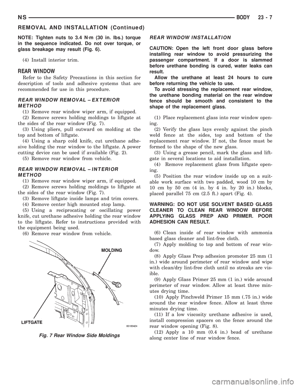
(2) Remove screws holding moldings to liftgate at
the sides of the rear window (Fig. 7).
(3) Using pliers, pull outward on molding at the
top and bottom of liftgate.
(4) Using a sharp cold knife, cut urethane adhe-
sive holding the rear window to the liftgate. A power
cutting device can be used if available (Fig. 2).
(5) Remove rear window from vehicle.
REAR WINDOW REMOVAL ± INTERIOR
METHOD
(1) Remove rear window wiper arm, if equipped.
(2) Remove screws holding moldings to liftgate at
the sides of the rear window (Fig. 7).
(3) Remove liftgate inside lamps and trim covers.
(4) Remove center high mounted stop lamp.
(5) Using a reciprocating or oscillating power
knife, cut urethane adhesive holding the rear window
to the liftgate. Refer to instructions provided with
the equipment being used.
(6) Remove rear window from vehicle.
REAR WINDOW INSTALLATION
CAUTION: Open the left front door glass before
installing rear window to avoid pressurizing the
passenger compartment. If a door is slammed
before urethane bonding is cured, water leaks can
result.
Allow the urethane at least 24 hours to cure
before returning the vehicle to use.
To avoid stressing the replacement rear window,
the urethane bonding material on the rear window
fence should be smooth and consistent to the
shape of the replacement glass.
(1) Place replacement glass into rear window open-
ing.
(2) Verify the glass lays evenly against the pinch
weld fence at the sides, top and bottom of the
replacement rear window. If not, the fence must be
formed to the shape of the new glass.
(3) Using a grease pencil, mark the glass and lift-
gate in several locations to aid installation.
(4) Remove replacement glass from liftgate open-
ing.
(5) Position the rear window inside up on a suit-
able work surface with two padded, wood 10 cm by
10 cm by 50 cm (4 in. by 4 in. by 20 in.) blocks,
placed parallel 75 cm (2.5 ft.) apart (Fig. 4).
WARNING: DO NOT USE SOLVENT BASED GLASS
CLEANER TO CLEAN REAR WINDOW BEFORE
APPLYING GLASS PREP AND PRIMER. POOR
ADHESION CAN RESULT.
(6) Clean inside of rear window with ammonia
based glass cleaner and lint-free cloth.
(7) Apply molding to top and bottom of rear win-
dow.
(8) Apply Glass Prep adhesion promoter 25 mm (1
in.) wide around perimeter of rear window and wipe
with clean/dry lint-free cloth until no streaks are vis-
ible.
(9) Apply Glass Primer 25 mm (1 in.) wide around
perimeter of rear window. Allow at least three min-
utes drying time.
(10) Apply Pinchweld Primer 15 mm (.75 in.) wide
around the rear window fence. Allow at least three
minutes drying time.
(11) If a low viscosity urethane adhesive is used,
install compression spacers on the fence around the
rear window opening (Fig. 8).
(12) Apply a 10 mm (0.4 in.) bead of urethane
along center line of rear window fence.
Fig. 7 Rear Window Side Moldings
NSBODY 23 - 7
REMOVAL AND INSTALLATION (Continued)
Page 1738 of 1938
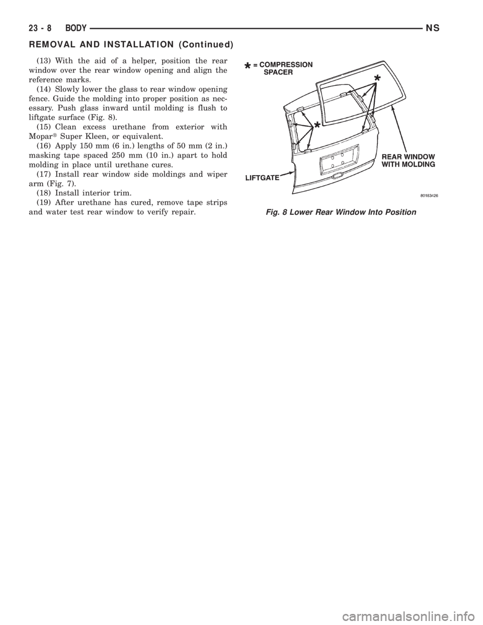
(13) With the aid of a helper, position the rear
window over the rear window opening and align the
reference marks.
(14) Slowly lower the glass to rear window opening
fence. Guide the molding into proper position as nec-
essary. Push glass inward until molding is flush to
liftgate surface (Fig. 8).
(15) Clean excess urethane from exterior with
MopartSuper Kleen, or equivalent.
(16) Apply 150 mm (6 in.) lengths of 50 mm (2 in.)
masking tape spaced 250 mm (10 in.) apart to hold
molding in place until urethane cures.
(17) Install rear window side moldings and wiper
arm (Fig. 7).
(18) Install interior trim.
(19) After urethane has cured, remove tape strips
and water test rear window to verify repair.
Fig. 8 Lower Rear Window Into Position
23 - 8 BODYNS
REMOVAL AND INSTALLATION (Continued)
Page 1752 of 1938
BODY COMPONENT SERVICE
INDEX
page page
DIAGNOSIS AND TESTING
WATER LEAKS.......................... 23
WIND NOISE........................... 24
SERVICE PROCEDURES
HEAT STAKING......................... 24
REMOVAL AND INSTALLATION
A-PILLAR LOWER EXTENSION TRIM........ 25
A-PILLAR TRIM PANEL................... 25
COWL COVER.......................... 25
COWL TRIM............................ 25
FLOOR CARPET........................ 26
FRONT DOOR APPLIQUE................. 28
FRONT DOOR CHECK STRAP.............. 28
FRONT DOOR FRAME CLOSEOUT MOLDINGS . 29
FRONT DOOR GLASS RUN WEATHER-STRIP . . 30
FRONT DOOR GLASS.................... 29
FRONT DOOR HINGE.................... 30
FRONT DOOR INNER BELT MOLDING....... 31
FRONT DOOR LATCH STRIKER............ 32
FRONT DOOR LATCH.................... 31
FRONT DOOR LOCK CYLINDER............ 32
FRONT DOOR OUTER BELT MOLDING....... 33
FRONT DOOR OUTSIDE HANDLE........... 33
FRONT DOOR REFLECTOR............... 34
FRONT DOOR SILL PLATE................ 34
FRONT DOOR TRIM PANEL................ 34
FRONT DOOR WEATHER-STRIP............ 36
FRONT DOOR WINDOW CRANK............ 36
FRONT DOOR WINDOW REGULATOR....... 36
FRONT DOOR.......................... 27
FRONT SEAT........................... 37
FRONT WHEELHOUSE SPLASH SHIELD..... 37
FUEL FILL DOOR BLOCKER LATCH STRIKER . . 38
FUEL FILL DOOR BLOCKER LATCH......... 38
FUEL FILL DOOR BLOCKER LOCKOUT LINK . . 38
FUEL FILLER HOUSING ± WITH BLOCKER
LATCH .............................. 39
GRILLE............................... 39
HEADLINING........................... 39
HOOD HINGE.......................... 41
HOOD LATCH STRIKER................... 42
HOOD LATCH.......................... 41
HOOD RELEASE CABLE.................. 42
HOOD RELEASE HANDLE................. 42
HOOD................................ 40
JACK STORAGE COVER.................. 43
LEFT D-PILLAR TRIM PANEL............... 43
LEFT QUARTER TRIM PANEL.............. 44
LIFTGATE CHMSL ACCESS PANEL.......... 47
LIFTGATE HINGE........................ 47LIFTGATE LATCH STRIKER................ 47
LIFTGATE LATCH........................ 47
LIFTGATE LOCK CYLINDER............... 48
LIFTGATE OUTSIDE HANDLE.............. 48
LIFTGATE PROP ASSEMBLY............... 49
LIFTGATE SILL PLATE.................... 49
LIFTGATE STABILIZER WEDGE STRIKER..... 49
LIFTGATE STABILIZER WEDGE............. 49
LIFTGATE TRIM PANEL................... 50
LIFTGATE UPPER FRAME MOLDING........ 50
LIFTGATE UPPER FRAME SIDE MOLDINGS . . . 51
LIFTGATE............................. 46
LOWER B-PILLAR TRIM COVER............ 51
LUGGAGE RACK CROSSBAR.............. 51
LUGGAGE RACK RISER COVER............ 52
LUGGAGE RACK SIDE RAIL............... 52
OVERHEAD GRAB-HANDLES.............. 52
QUARTER GLASS....................... 52
QUARTER TRIM BOLSTER................ 53
RADIATOR CLOSURE PANEL CROSSMEMBER . 53
RAIL LAMP MODULE..................... 54
REAR HEADER TRIM..................... 55
REAR HVAC LOUVER AND BEZEL.......... 55
RIGHT D-PILLAR TRIM PANEL.............. 55
RIGHT QUARTER TRIM PANEL............. 56
ROOF APERTURE (RAP) MOLDING.......... 57
SEAT BELT BUCKLE FIRST REAR QUAD
BUCKET............................. 58
SEAT BELT BUCKLE FIRST REAR ± TWO
PASSENGER BENCH................... 58
SEAT BELT BUCKLE SECOND REAR ± THREE
PASSENGER BENCH................... 59
SEAT BELT BUCKLE ± FRONT INBOARD..... 57
SEAT BELT FIRST REAR ANCHOR BRACKET ±
LWB ................................ 59
SEAT BELT FIRST REAR OUTBOARD ± LWB
FOUR DOOR.......................... 60
SEAT BELT FIRST REAR OUTBOARD ± SWB
FOUR DOOR.......................... 60
SEAT BELT LEFT FIRST REAR OUTBOARD ±
LWB THREE DOOR..................... 61
SEAT BELT LEFT FIRST REAR OUTBOARD ±
SWB THREE DOOR.................... 61
SEAT BELT SECOND REAR OUTBOARD ±
SWB ................................ 61
SEAT BELT SECOND RIGHT REAR OUTBOARD
±LWB ............................... 62
SEAT BELT ± OUTBOARD FRONT........... 59
SECOND RIGHT REAR OUTBOARD SEAT BELT
± LWB W/REAR HVAC................... 62
23 - 22 BODYNS
Page 1754 of 1938
Some water leaks must be tested for a considerable
length of time to become apparent. When a leak
appears, find the highest point of the water track or
drop. The highest point usually will show the point of
entry. After leak point has been found, repair the
leak and water test to verify that the leak has
stopped.
Locating the entry point of water that is leaking
into a cavity between panels can be difficult. The
trapped water may splash or run from the cavity,
often at a distance from the entry point. Most water
leaks of this type become apparent after accelerating,
stopping, turning, or when on an incline.
MIRROR INSPECTION METHOD
When a leak point area is visually obstructed, use
a suitable mirror to gain visual access. A mirror can
also be used to deflect light to a limited-access area
to assist in locating a leak point.
BRIGHT LIGHT LEAK TEST METHOD
Some water leaks in the luggage compartment can
be detected without water testing. Position the vehi-
cle in a brightly lit area. From inside the darkened
luggage compartment inspect around seals and body
seams. If necessary, have a helper direct a drop light
over the suspected leak areas around the luggage
compartment. If light is visible through a normally
sealed location, water could enter through the open-
ing.
PRESSURIZED LEAK TEST METHOD
When a water leak into the passenger compart-
ment cannot be detected by water testing, pressurize
the passenger compartment and soap test exterior of
the vehicle. To pressurize the passenger compart-
ment, close all doors and windows, start engine, and
set heater control to high blower in HEAT position. If
engine can not be started, connect a charger to the
battery to ensure adequate voltage to the blower.
With interior pressurized, apply dish detergent solu-
tion to suspected leak area on the exterior of the
vehicle. Apply detergent solution with spray device or
soft bristle brush. If soap bubbles occur at a body
seam, joint, seal or gasket, the leak entry point could
be at that location.
WIND NOISE
Wind noise is the result of most air leaks. Air leaks
can be caused by poor sealing, improper body compo-
nent alignment, body seam porosity, or missing plugs
in the engine compartment or door hinge pillar areas.
All body sealing points should be airtight in normal
driving conditions. Moving sealing surfaces will not
always seal airtight under all conditions. At times,
side glass or door seals will allow wind noise to be
noticed in the passenger compartment during highcrosswinds. Over compensating on door or glass
adjustments to stop wind noise that occurs under
severe conditions can cause premature seal wear and
excessive closing or latching effort. After a repair pro-
cedure has been performed, test vehicle to verify
noise has stopped before returning vehicle to use.
Wind noise can also be caused by improperly fitted
exterior moldings or body ornamentation. Loose
moldings can flutter, creating a buzzing or chattering
noise. An open cavity or protruding edge can create a
whistling or howling noise. Inspect the exterior of the
vehicle to verify that these conditions do not exist.
VISUAL INSPECTION BEFORE TESTS
Verify that floor and body plugs are in place and
body components are aligned and sealed. If component
alignment or sealing is necessary, refer to the appro-
priate section of this group for proper procedures.
ROAD TESTING WIND NOISE
(1) Drive the vehicle to verify the general location
of the wind noise.
(2) Apply 50 mm (2 in.) masking tape in 150 mm
(6 in.) lengths along weatherstrips, weld seams or
moldings. After each length is applied, drive the vehi-
cle. If noise goes away after a piece of tape is applied,
remove tape, locate, and repair defect.
POSSIBLE CAUSE OF WIND NOISE
²Moldings standing away from body surface can
catch wind and whistle.
²Gaps in sealed areas behind overhanging body
flanges can cause wind-rushing sounds.
²Misaligned movable components.
²Missing or improperly installed plugs in pillars.
²Weld burn through holes.
SERVICE PROCEDURES
HEAT STAKING
(1) Remove trim panel.
(2) Bend or move the trim panel components at
the heat staked joints. Observe the heat staked loca-
tions and/or component seams for looseness.
(3) Heat stake the components.
(a) If the heat staked or component seam loca-
tion is loose, hold the two components tightly
together and using a soldering gun with a flat tip,
melt the material securing the components
together. Do not over heat the affected area, dam-
age to the exterior of the trim panel may occur.
(b) If the heat staked material is broken or miss-
ing, use a hot glue gun to apply new material to
the area to be repaired. The panels that are being
heat staked must be held together while the apply-
ing the glue. Once the new material is in place, it
23 - 24 BODYNS
DIAGNOSIS AND TESTING (Continued)