window CHRYSLER VOYAGER 1996 Manual Online
[x] Cancel search | Manufacturer: CHRYSLER, Model Year: 1996, Model line: VOYAGER, Model: CHRYSLER VOYAGER 1996Pages: 1938, PDF Size: 55.84 MB
Page 1820 of 1938
absorb moisture readily out of the air. This moisture
will convert into acids within a closed system.
CAUTION: The system must be completely empty
before opening any fitting or connection in the
refrigeration system. Open fittings with caution
even after the system has been emptied. If any
pressure is noticed as a fitting is loosened,
retighten fitting and evacuate the system again.
A good rule for the flexible hose lines is to keep
the radius of all bends at least 10 times the diame-
ter of the hose. Sharper bends will reduce the flow
of refrigerant. The flexible hose lines should be
routed so they are at least 3 inches (80 mm) from
the exhaust manifold. Inspect all flexible hose lines
to make sure they are in good condition and prop-
erly routed.
The use of correct wrenches when making con-
nections is very important. Improper wrenches or
improper use of wrenches can damage the fittings.
The internal parts of the A/C system will remain
stable as long as moisture-free refrigerant and
refrigerant oil is used. Abnormal amounts of dirt,
moisture or air can upset the chemical stability.
This may cause operational troubles or even seri-
ous damage if present in more than very small
quantities.
When opening a refrigeration system, have every-
thing you will need to repair the system ready. This
will minimize the amount of time the system must
be opened. Cap or plug all lines and fittings as
soon as they are opened. This will help prevent the
entrance of dirt and moisture. All new lines and
components should be capped or sealed until they
are ready to be used.
All tools, including the refrigerant dispensing
manifold, the manifold gauge set, and test hoses
should be kept clean and dry.
HVAC CONTROL MODULE
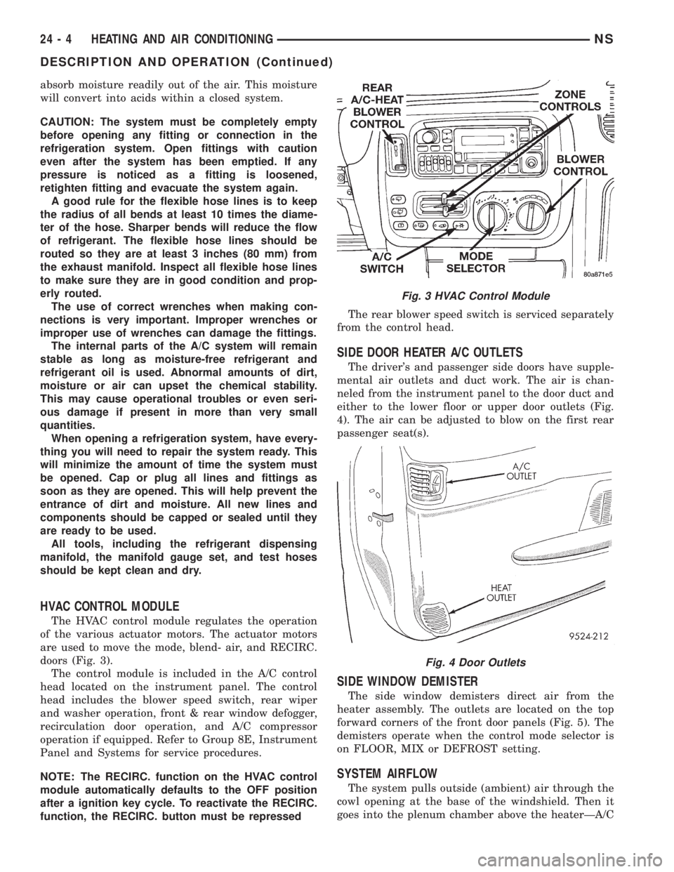
The HVAC control module regulates the operation
of the various actuator motors. The actuator motors
are used to move the mode, blend- air, and RECIRC.
doors (Fig. 3).
The control module is included in the A/C control
head located on the instrument panel. The control
head includes the blower speed switch, rear wiper
and washer operation, front & rear window defogger,
recirculation door operation, and A/C compressor
operation if equipped. Refer to Group 8E, Instrument
Panel and Systems for service procedures.
NOTE: The RECIRC. function on the HVAC control
module automatically defaults to the OFF position
after a ignition key cycle. To reactivate the RECIRC.
function, the RECIRC. button must be repressedThe rear blower speed switch is serviced separately
from the control head.
SIDE DOOR HEATER A/C OUTLETS
The driver's and passenger side doors have supple-
mental air outlets and duct work. The air is chan-
neled from the instrument panel to the door duct and
either to the lower floor or upper door outlets (Fig.
4). The air can be adjusted to blow on the first rear
passenger seat(s).
SIDE WINDOW DEMISTER
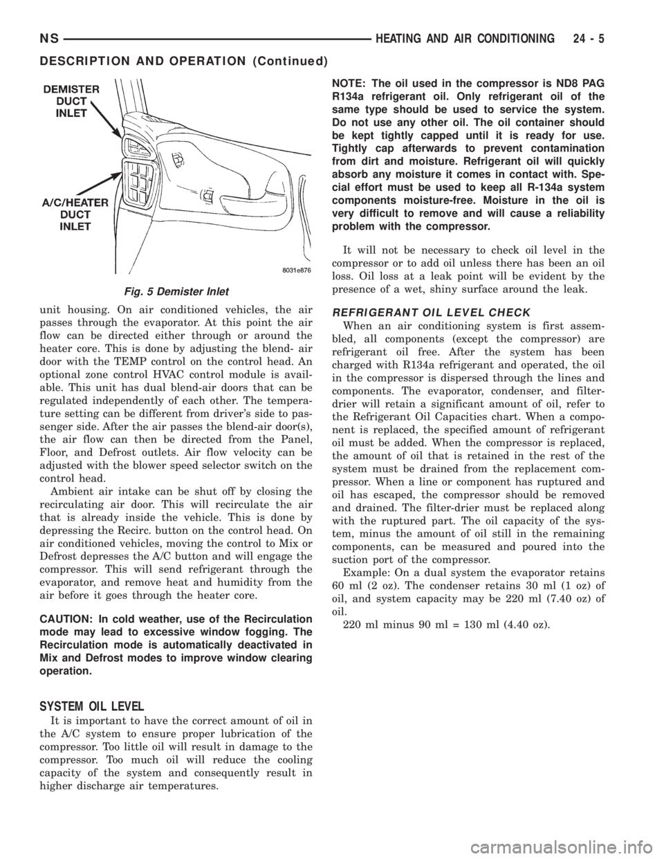
The side window demisters direct air from the
heater assembly. The outlets are located on the top
forward corners of the front door panels (Fig. 5). The
demisters operate when the control mode selector is
on FLOOR, MIX or DEFROST setting.
SYSTEM AIRFLOW
The system pulls outside (ambient) air through the
cowl opening at the base of the windshield. Then it
goes into the plenum chamber above the heaterÐA/C
Fig. 3 HVAC Control Module
Fig. 4 Door Outlets
24 - 4 HEATING AND AIR CONDITIONINGNS
DESCRIPTION AND OPERATION (Continued)
Page 1821 of 1938
unit housing. On air conditioned vehicles, the air
passes through the evaporator. At this point the air
flow can be directed either through or around the
heater core. This is done by adjusting the blend- air
door with the TEMP control on the control head. An
optional zone control HVAC control module is avail-
able. This unit has dual blend-air doors that can be
regulated independently of each other. The tempera-
ture setting can be different from driver's side to pas-
senger side. After the air passes the blend-air door(s),
the air flow can then be directed from the Panel,
Floor, and Defrost outlets. Air flow velocity can be
adjusted with the blower speed selector switch on the
control head.
Ambient air intake can be shut off by closing the
recirculating air door. This will recirculate the air
that is already inside the vehicle. This is done by
depressing the Recirc. button on the control head. On
air conditioned vehicles, moving the control to Mix or
Defrost depresses the A/C button and will engage the
compressor. This will send refrigerant through the
evaporator, and remove heat and humidity from the
air before it goes through the heater core.
CAUTION: In cold weather, use of the Recirculation
mode may lead to excessive window fogging. The
Recirculation mode is automatically deactivated in
Mix and Defrost modes to improve window clearing
operation.
SYSTEM OIL LEVEL
It is important to have the correct amount of oil in
the A/C system to ensure proper lubrication of the
compressor. Too little oil will result in damage to the
compressor. Too much oil will reduce the cooling
capacity of the system and consequently result in
higher discharge air temperatures.NOTE: The oil used in the compressor is ND8 PAG
R134a refrigerant oil. Only refrigerant oil of the
same type should be used to service the system.
Do not use any other oil. The oil container should
be kept tightly capped until it is ready for use.
Tightly cap afterwards to prevent contamination
from dirt and moisture. Refrigerant oil will quickly
absorb any moisture it comes in contact with. Spe-
cial effort must be used to keep all R-134a system
components moisture-free. Moisture in the oil is
very difficult to remove and will cause a reliability
problem with the compressor.
It will not be necessary to check oil level in the
compressor or to add oil unless there has been an oil
loss. Oil loss at a leak point will be evident by the
presence of a wet, shiny surface around the leak.
REFRIGERANT OIL LEVEL CHECK
When an air conditioning system is first assem-
bled, all components (except the compressor) are
refrigerant oil free. After the system has been
charged with R134a refrigerant and operated, the oil
in the compressor is dispersed through the lines and
components. The evaporator, condenser, and filter-
drier will retain a significant amount of oil, refer to
the Refrigerant Oil Capacities chart. When a compo-
nent is replaced, the specified amount of refrigerant
oil must be added. When the compressor is replaced,
the amount of oil that is retained in the rest of the
system must be drained from the replacement com-
pressor. When a line or component has ruptured and
oil has escaped, the compressor should be removed
and drained. The filter-drier must be replaced along
with the ruptured part. The oil capacity of the sys-
tem, minus the amount of oil still in the remaining
components, can be measured and poured into the
suction port of the compressor.
Example: On a dual system the evaporator retains
60 ml (2 oz). The condenser retains 30 ml (1 oz) of
oil, and system capacity may be 220 ml (7.40 oz) of
oil.
220 ml minus 90 ml = 130 ml (4.40 oz).
Fig. 5 Demister Inlet
NSHEATING AND AIR CONDITIONING 24 - 5
DESCRIPTION AND OPERATION (Continued)
Page 1824 of 1938
COOLDOWN TEST ENTRY
TO INITIATE TESTS:
²Set Blower motor ON HIGH
²Set Mode position to Panel
²Open all A/C outlets
²Set Temperature to Cold (Both slide pots if
equipped)
²Depress WASH and A/C simultaneously for 5
Seconds
NOTE: Prior to start of test, If the evaporator is
already cold, the system will fail test. To correct,
operate system with A/C OFF and the blower motor
ON high for three minutes prior to starting test.
RESULTS:
²All LED's will turn on for 5 Seconds
²Cooldown Test is running when A/C and
RECIRC. are alternately flashing. If A/C and
RECIRC. are flashing simultaneously, Cooldown has
failed.
CALIBRATION DIAGNOSTICS AND
COOLDOWN ABORT
Test can be aborted by doing one of the following:
²Depressing Rear Window Defogger, RECIRC and
Rear Wiper buttons.
²Cycling Ignition OFF and then ON.
²Control will automatically abort after 15 min-
utes from the time Calibration Diagnostics and
Cooldown was entered.
The HVAC control module will return to normal
operation or may indicate unsuccessful Calibration
Diagnostics or Cooldown test by LED's flashing
simultaneously.
EEPROM DATA
Calibration Diagnostics, Cooldown Status and
evaporator temperature Fin Sensor values are stored
in an EEPROM memory internal to the control. The
microcomputer within the HVAC control module uses
this information:
²To determine if Cooldown needs to run
²For proper position of the Heater-A/C unit
assembly doors
ACTUATOR CALIBRATION AND
DIAGNOSTICS.
NOTE: Do not run actuators unless they are prop-
erly mounted on the HVAC control module.
Actuator end point calibration takes approximately
60 seconds. The REAR WIPER and INTERMITTENT
LED's will flash alternately during the test. The con-
trol will cycle the Blend actuator(s) to the Heat stopfirst then back to Cold. After the Blend actuator(s)
have been calibrated the Mode actuator will be cycled
to Defrost and then to Panel. Successful calibration
is defined as actuator travel falling within their min-
imum and maximum limits.
BLEND/PASSENGER ACTUATOR BACKGROUND
The Blend/Passenger Actuator can move the tem-
perature door in two directions. When the voltage at
Pin 12 of the control module is high, about 11.5 volts,
and the voltage at Pin 17 is low, about 1.5 volts, the
door will move towards the Heat position. When Pin
17 is High and Pin 12 is Low the door will move
towards the Cold position. When both Pins are high
or both Pins are low, the actuator will not move. The
Blend/Passenger feedback signal is a voltage signal
that is supplied by the actuator to the control. The
signal will be about 4.0 volts in the Heat position
and 1.0 volt in the Cold position. As the position of
the Blend/Passenger actuator changes, so will the
feedback signal. The feedback signal is necessary for
the correct positioning of the temperature door.
DRIVER ACTUATOR BACKGROUND
The Driver Actuator can move the temperature
door in two directions. When the voltage at Pin 15 of
the control module is high, about 11.5 volts, and the
voltage at Pin 13 is low, about 1.5 volts the door will
move towards the Cold position. When Pin 13 is High
and Pin 15 is Low the door will move towards the
Heat position. When both Pins are high or when both
Pins are low, the actuator will not move. The Driver
feedback signal is a voltage signal that is supplied by
the actuator to the control. The signal will be about
4.0 volts in the Heat position and 1.0 volt in the Cold
position. As the position of the Driver Actuator
changes, so will the feedback signal. The feedback
signal is necessary for the correct positioning of the
temperature door.
MODE ACTUATOR BACKGROUND
The Mode actuator can move the mode door in two
directions. When the voltage at Pin 18 of the control
module is high, about 11.5 volts, and the voltage at
Pin 12 is low, about 1.5 volts the door will move
towards the Panel position. When Pin 12 is High and
Pin 18 is Low the door will move towards the Defrost
position. When both Pin are high or when both Pins
are low, the actuator will not move. The Mode door
feedback signal is a voltage signal that is supplied by
the actuator to the control. The signal will be about
4.5 volts in the Panel position and 0.5 volts in the
Defrost position. As the position of the Mode actuator
changes, so will the feedback signal. The feedback
signal is necessary for the correct positioning of the
mode door.
24 - 8 HEATING AND AIR CONDITIONINGNS
DIAGNOSIS AND TESTING (Continued)
Page 1828 of 1938
probe will drop the temperature 7ÉC (20ÉF) in two
minutes. If the Evaporator Probe is found to be
faulty, check that the sensor is positioned in the
evaporator fins properly. If not, correct and repeat
test. If OK, replace the evaporator probe.
Once the repairs are completed, repeat the Calibra-
tion Diagnostic and Cooldown test. Repeating the
test is necessary to clear the fault codes.
A/C PERFORMANCE TEST
The air conditioning system is designed to remove
heat and humidity from the air entering the passen-
ger compartment. The evaporator, located in the
heater A/C unit, is cooled to temperatures near the
freezing point. As warm damp air passes over the
fins in the evaporator, moisture in the air condenses
to water, dehumidifying the air. Condensation on the
evaporator fins reduces the evaporators ability to
absorb heat. During periods of high heat and humid-
ity, an air conditioning system will be less effective.
With the instrument control set to RECIRC, only air
from the passenger compartment passes through the
evaporator. As the passenger compartment air dehu-
midifies, A/C performance levels rise.
PERFORMANCE TEST PROCEDURE
Review Safety Precautions and Warnings in this
group before proceeding with this procedure. Air tem-
perature in test room and on vehicle must be 21É C
(70ÉF) minimum for this test.
NOTE: When connecting the service equipment
coupling to the line fitting, verify that the valve of
the coupling is fully closed. This will reduce the
amount of effort required to make the connection.
(1) Connect a tachometer and manifold gauge set.
(2) Set control to A/C, RECIRC, and PANEL, tem-
perature lever on full cool and blower on high.
(3) Start engine and hold at 1000 rpm with A/C
clutch engaged.(4) Engine should be warmed up with doors and
windows closed.
(5) Insert a thermometer in the left center A/C
outlet and operate the engine for five minutes. The
A/C clutch may cycle depending on ambient condi-
tions.
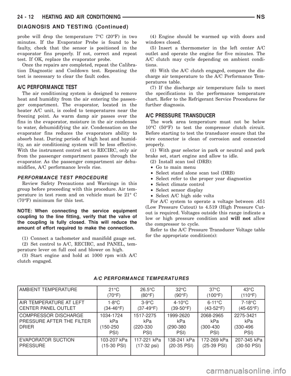
(6) With the A/C clutch engaged, compare the dis-
charge air temperature to the A/C Performance Tem-
peratures table.
(7) If the discharge air temperature fails to meet
the specifications in the performance temperature
chart. Refer to the Refrigerant Service Procedures for
further diagnosis.
A/C PRESSURE TRANSDUCER
The work area temperature must not be below
10ÉC (50ÉF) to test the compressor clutch circuit.
Before starting to test the transducer ensure that the
wire connector is clean of corrosion and connected
properly.
(1) With gear selector in park or neutral and park
brake set, start engine and allow to idle.
(2) Install scan tool (DRB):
²Go to main menu
²Select stand alone scan tool (DRB)
²Select refer to the proper year diagnostics
²Select climate control
²Select sensor display
²Select A/C high side volts
For A/C system to operate a voltage between .451
(Low Pressure Cutout) to 4.519 (High Pressure Cut-
out is required. Voltages outside this range indicate a
low or high pressure condition andwill notallow
the compressor to cycle.
Refer to the A/C Pressure Transducer Voltage table
for the appropriate condition(s):
A/C PERFORMANCE TEMPERATURES
AMBIENT TEMPERATURE 21ÉC
(70ÉF)26.5ÉC
(80ÉF)32ÉC
(90ÉF)37ÉC
(100ÉF)43ÉC
(110ÉF)
AIR TEMPERATURE AT LEFT
CENTER PANEL OUTLET1-8ÉC
(34-46ÉF)3-9ÉC
(37-49ÉF)4-10ÉC
(39-50ÉF)6-11ÉC
(43-52ÉF)7-18ÉC
(45-65ÉF)
COMPRESSOR DISCHARGE
PRESSURE AFTER THE FILTER
DRIER1034-1724
kPa
(150-250
PSI)1517-2275
kPa
(220-330
PSI)1999-2620
kPa
(290-380
PSI)2068-2965
kPa
(300-430
PSI)2275-3421
kPa
(330-496
PSI)
EVAPORATOR SUCTION
PRESSURE103-207 kPa
(15-30 PSI)117-221 kPa
(17-32 psi)138-241 kPa
(20-35 PSI)172-269 kPa
(25-39 PSI)207-345 kPa
(30-50 PSI)
24 - 12 HEATING AND AIR CONDITIONINGNS
DIAGNOSIS AND TESTING (Continued)
Page 1831 of 1938
be 21ÉC to 27ÉC (70ÉF to 85ÉF). To test the expansion
valve:
NOTE: Liquid CO2 is required to test the expansion
valve. It is available from most welding supply facil-
ities. CO2 is also available from companies which
service and sell fire extinguishers.
(1) Connect a charging station or manifold gauge
set to the refrigerant system service ports. Verify the
refrigerant charge level.
(2) Close all doors, windows and vents to the pas-
senger compartment.
(3) Set heater A/C control to A/C, full heat,
FLOOR, and high blower.
(4) Start the engine and allow to idle (1000 rpm).
After the engine has reached running temperature,
allow the passenger compartment to heat up. This
will create the need for maximum refrigerant flow
into the evaporator.
(5) If the refrigerant charge is sufficient, discharge
(high pressure) gauge should read 965 to 1655 kPa
(140 to 240 psi). Suction (low pressure) gauge should
read 140 kPa to 207 kPa (20 psi to 30 psig). If system
cannot achieve proper pressure readings, replace the
expansion valve. If pressure is correct, proceed with
test.
WARNING: PROTECT SKIN AND EYES FROM CON-
TACTING CO2 PERSONAL INJURY CAN RESULT.
(6) If suction side low pressure is within specified
range, freeze the expansion valve control head for 30
seconds. Use a super cold substance (liquid CO2).Do
not spray R-134a or R-12 Refrigerant on the
expansion valve for this test.Suction side low
pressure should drop by 10 psi. If not, replace expan-
sion valve.
(7) Allow expansion valve to thaw. The low pres-
sure gauge reading should stabilize at 140 kPa to
240 kPa (20 psi to 30 psig). If not, replace expansion
valve.
(8) When expansion valve test is complete, test
A/C overall performance. Remove all test equipment
before returning vehicle to use.
HEATER PERFORMANCE TEST
PRE-DIAGNOSTIC PREPARATIONS
Review Safety Precautions and Warnings in this
group before performing the following procedures.
Check the coolant level, drive belt tension, vacuum
line connections, radiator air flow and fan operation.
Start engine and allow to warm up to normal tem-
perature.WARNING: DO NOT REMOVE RADIATOR CAP
WHEN ENGINE IS HOT, PERSONAL INJURY CAN
RESULT.
If vehicle has been run recently, wait 15 minutes
before removing cap. Place a rag over the cap and
turn it to the first safety stop. Allow pressure to
escape through the overflow tube. When the system
stabilizes, remove the cap completely.
MAXIMUM HEATER OUTPUT: TEST AND
ACTION
Engine coolant is provided to the heater system by
two 16 mm (5/8 inch inside diameter) heater hoses.
With engine idling at normal running temperature,
set the control to maximum heat, floor, and high
blower setting. Using a test thermometer, check the
air temperature coming from the floor outlets, refer
to Temperature Reference Table.
If the floor outlet air temperature is insufficient,
refer to Group 7, Cooling Systems for specifications.
Both heater hoses should be HOT to the touch (cool-
ant return hose should be slightly cooler than the
supply hose). If coolant return hose is much cooler
than the supply hose, locate and repair engine cool-
ant flow obstruction in heater system.
POSSIBLE LOCATIONS OR CAUSE OF
OBSTRUCTED COOLANT FLOW
(1) Pinched or kinked heater hoses.
(2) Improper heater hose routing.
(3) Plugged heater hoses or supply and return
ports at cooling system connections, refer to Group 7,
Cooling System.
(4) Plugged heater core.
(5) Air locked heater core.
(6) If coolant flow is verified and outlet tempera-
ture is insufficient, a mechanical problem may exist.
POSSIBLE LOCATION OR CAUSE OF
INSUFFICIENT HEAT
(1) Obstructed cowl air intake.
(2) Obstructed heater system outlets.
(3) Blend-air door not functioning properly.
TEMPERATURE REFERENCE TABLE
AMBIENT
TEMPERATUREMINIMUM FLOOR
OUTLET TEMPERATURE
CELSIUS FAHRENHEIT CELSIUS FAHRENHEIT
15.5É 60É 62.2É 144É
21.1É 70É 63.8É 147É
26.6É 80É 65.5É 150É
32.2É 90É 67.2É 153É
NSHEATING AND AIR CONDITIONING 24 - 15
DIAGNOSIS AND TESTING (Continued)
Page 1832 of 1938
TEMPERATURE CONTROL
If temperature cannot be adjusted with the TEMP
lever on the control panel, the following could require
service:
(1) Blend-air door binding.
(2) Faulty blend-air door motor.
(3) Improper engine coolant temperature.
(4) Faulty Instrument Panel Control.
SYSTEM CHARGE LEVEL TEST
The procedure below should be used to check
and/or fill the refrigerant charge in the air condition-
ing system.
NOTE: The amount of R134a refrigerant that the air
conditioning system holds is:
²Without rear A/C± .96 kg (34 oz. or 2.13 lbs.)
²With Rear A/C± 1.36 kg (48 oz. or 3.00 lbs.)
NOTE: Low Charge, condition may be described
as:
²Loss of A/C performance
²Fog from A/C outlets
²evaporator may have a HISS sound
There are two different ways the system can be
tested:
²With a scan tool (DRB), thermocouple and the
Charge Determination Graph. Use the scan tool
(DRB) diagnostic topic: Engine±System Monitors, A/C
Pressure.
²Using a manifold gauge set, a thermocouple and
the Charge Determination Graph.
It is recommended to use the gauges or reclaim/re-
cycle equipment.
WARNING: AVOID BREATHING A/C REFRIGERANT
AND LUBRICANT VAPOR OR MIST. EXPOSURE MAY
IRRITATE EYES, NOSE AND THROAT. USE ONLY
APPROVED SERVICE EQUIPMENT MEETING SAE
REQUIREMENTS TO DISCHARGE R-134a SYSTEM.
IF ACCIDENTAL SYSTEM DISCHARGE OCCURS,
VENTILATE WORK AREA BEFORE RESUMING SER-
VICE.
R-134a SERVICE EQUIPMENT OR VEHICLE A/C
SYSTEM SHOULD NOT BE PRESSURE TESTED OR
LEAK TESTED WITH COMPRESSED AIR. SOME
MIXTURES OF AIR/R-134a HAVE BEEN SHOWN TO
BE COMBUSTIBLE AT ELEVATED PRESSURES.
THESE MIXTURES ARE POTENTIALLY DANGER-
OUS AND MAY RESULT IN FIRE OR EXPLOSION
CAUSING INJURY OR PROPERTY DAMAGE.
(1) Establish your preferred method of measuring
liquid line pressure. Use a manifold gauge set or a
DRB scan tool.(2) Attach a clamp-on thermocouple (P.S.E. 66-324-
0014 or 80PK-1A) or equivalent to the liquid line. It
must be placed as close to the A/C Pressure Trans-
ducer as possible to observe liquid line temperature.
Refer to ªThermocouple Probeº in this section for
more information on probe.
(3) The vehicle must be in the following modes:
²Transaxle in Park
²Engine Idling at 700 rpm
²A/C Controls Set to Outside Air
²Panel Mode
²Full Cool
²High Blower motor, (vehicle equipped with rear
A/C turn rear blower motor ON HIGH)
²A/C Button in the ON position
²Vehicle Windows Open.
²Recirc. button turned OFF
(4) Operate system for a couple of minutes to allow
the system to stabilize.
(5) Set system pressure to about 1793 kPa (260
psi) by placing a piece of cardboard over part of the
front side of the condenser. To place cardboard prop-
erly, remove the upper radiator-condenser cover.
Insert cardboard between condenser and radiator
front. This will maintain a constant pressure.
(6) Observe Liquid Line pressure and Liquid line
temperature. Using theCharge Determination
Chartdetermine where the system is currently oper-
ating. If the system is in the undercharged region,
ADD 0.057 Kg. (2 oz.) to the system and recheck
readings. If the system is in the overcharged region,
RECLAIM 0.057 Kg. (2 oz.) from the system and
recheck readings. Continue this process until the sys-
tem readings are in the proper charge area on the
Charge Determination Chart.
(7) The same procedure can be performed using
the scan tool (DRB). To determine liquid line pres-
sure, attach the scan tool, go to System Moni-
tors±A/C Pressure. Observe liquid line pressure from
A/C Pressure Transducer on digital display and digi-
tal thermometer. Refer toCharge Determination
Chartand determine where the system is operating.
SERVICE PROCEDURES
R-134a REFRIGERANT
This vehicle uses a new type of refrigerant called
R-134a. It is a non-toxic, non-flammable, clear color-
less liquefied gas.
R-134a refrigerant is not compatible with R-12
refrigerant in an air conditioning system. Even a
small amount of R-12 in a R-134a system could cause
compressor failure, refrigerant oil to sludge and/or
poor performance.Never add any other type of
refrigerant to a system designed to use R-134a
refrigerant. System failure will occur.
24 - 16 HEATING AND AIR CONDITIONINGNS
DIAGNOSIS AND TESTING (Continued)
Page 1834 of 1938
NOTE: When connecting the service equipment
coupling to the line fitting, verify that the valve of
the coupling is fully closed. This will reduce the
amount of effort required to make the connection.
(1) Connect manifold gauge set.
(2) Measure refrigerant (refer to capacities) and
heat to 52ÉC (125ÉF) with the charging station. Refer
to the instructions provided with the equipment
being used.
REFRIGERANT CAPACITIES
²Without Rear A/C = .96 kg (34 oz. or 2.13lb.)
²With Rear A/C = 1.36 kg (48 oz. or 3.00 lb.)
(3) Open the suction and discharge valves. Open
the charge valve to allow the heated refrigerant to
flow into the system. When the transfer of refriger-
ant has stopped, close the suction and discharge
valve.
(4) If all of the charge did not transfer from the
dispensing device, run engine at a high idle (1400
rpm). Set the A/C control to A/C, low blower speed,
and open windows. If the A/C compressor does not
engage, test the compressor clutch control circuit and
correct any failure. Refer to Group 8W, Wiring Dia-
grams.
(5) Open the suction valve to allow the remaining
refrigerant to transfer to the system.
WARNING: TAKE CARE NOT TO OPEN THE DIS-
CHARGE (HIGH-PRESSURE) VALVE AT THIS TIME.(6) Close all valves and test the A/C system perfor-
mance.
(7) Disconnect the charging station or manifold
gauge set. Install the service port caps.
EVACUATING REFRIGERANT SYSTEM
NOTE: Special effort must be used to prevent mois-
ture from entering the A/C system oil. Moisture in
the oil is very difficult to remove and will cause a
reliability problem with the compressor.
If a compressor designed to use R-134a refrigerant
is left open to the atmosphere for an extended period
of time. It is recommended that the refrigerant oil be
drained and replaced with new oil or a new compres-
sor be used. This will eliminate the possibility of con-
taminating the refrigerant system.
If the refrigerant system has been open to the
atmosphere, it must be evacuated before the system
can be filled. Moisture and air mixed with the refrig-
erant will raise the compressor head pressure above
acceptable operating levels. This will reduce the per-
formance of the air conditioner and damage the com-
pressor. Moisture will boil at near room temperature
when exposed to vacuum. To evacuate the refrigerant
system:
NOTE: When connecting the service equipment
coupling to the line fitting, verify that the valve of
the coupling is fully closed. This will reduce the
amount of effort required to make the connection.
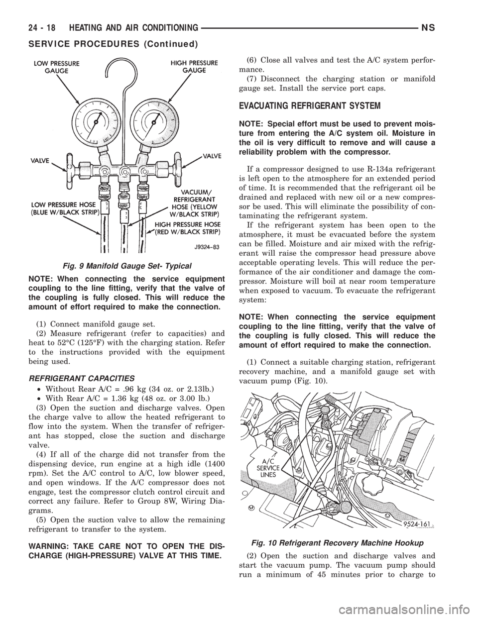
(1) Connect a suitable charging station, refrigerant
recovery machine, and a manifold gauge set with
vacuum pump (Fig. 10).
(2) Open the suction and discharge valves and
start the vacuum pump. The vacuum pump should
run a minimum of 45 minutes prior to charge to
Fig. 9 Manifold Gauge Set- Typical
Fig. 10 Refrigerant Recovery Machine Hookup
24 - 18 HEATING AND AIR CONDITIONINGNS
SERVICE PROCEDURES (Continued)
Page 1836 of 1938
²Transaxle in Park
²Engine Idling at 700 rpm
²A/C Controls Set in 100 percent outside air
²Full Panel Mode
²Blower motor ON HIGH
²A/C in the ON position
²Front Windows Open.
²Rear Air Off (If Equipped)
CAUTION: A leak detector designed for R-12 refrig-
erant will not detect leaks in a R-134a refrigerant
system.
(4) Shut off the vehicle and wait 2 to 7 minutes.
Then use an Electronic Leak Detector that is
designed to detect R-134a type refrigerant and search
for leaks. Fittings, lines, or components that appear
to be oily usually indicates a refrigerant leak. To
inspect the evaporator core for leaks, insert the leak
detector probe into the recirculating air door opening
or a heat duct.
If a thorough leak check has been completed with-
out indication of a leak, proceed to System Charge
Level-Check or Fill.
REMOVAL AND INSTALLATION
A/C PRESSURE TRANSDUCER
REMOVAL
(1) Disconnect the wire connector at the pressure
transducer.
(2) Using an open end wrench, remove the trans-
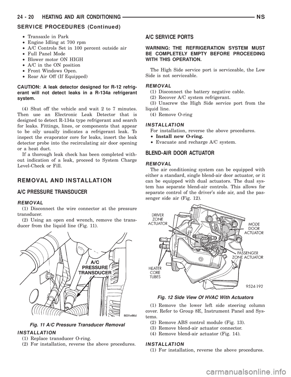
ducer from the liquid line (Fig. 11).
INSTALLATION
(1) Replace transducer O-ring.
(2) For installation, reverse the above procedures.
A/C SERVICE PORTS
WARNING: THE REFRIGERATION SYSTEM MUST
BE COMPLETELY EMPTY BEFORE PROCEEDING
WITH THIS OPERATION.
The High Side service port is serviceable, the Low
Side is not serviceable.
REMOVAL
(1) Disconnect the battery negative cable.
(2) Recover A/C system refrigerant.
(3) Unscrew the High Side service port from the
liquid line.
(4) Remove O-ring
INSTALLATION
For installation, reverse the above procedures.
²Install new O-ring.
²Evacuate and recharge A/C system.
BLEND-AIR DOOR ACTUATOR
REMOVAL
The air conditioning system can be equipped with
either a standard, single blend-air door actuator, or it
can be equipped with dual actuators. The dual sys-
tem has separate blend-air controls. This allows for
separate control of the driver's side air, and the pas-
senger side air (Fig. 12).
(1) Remove the lower left side steering column
cover. Refer to Group 8E, Instrument Panel and Sys-
tems.
(2) Remove ABS control module (Fig. 13).
(3) Remove blend-air actuator connector.
(4) Remove blend-air actuator (Fig. 14).
INSTALLATION
(1) For installation, reverse the above procedures.
Fig. 11 A/C Pressure Transducer Removal
Fig. 12 Side View Of HVAC With Actuators
24 - 20 HEATING AND AIR CONDITIONINGNS
SERVICE PROCEDURES (Continued)
Page 1849 of 1938
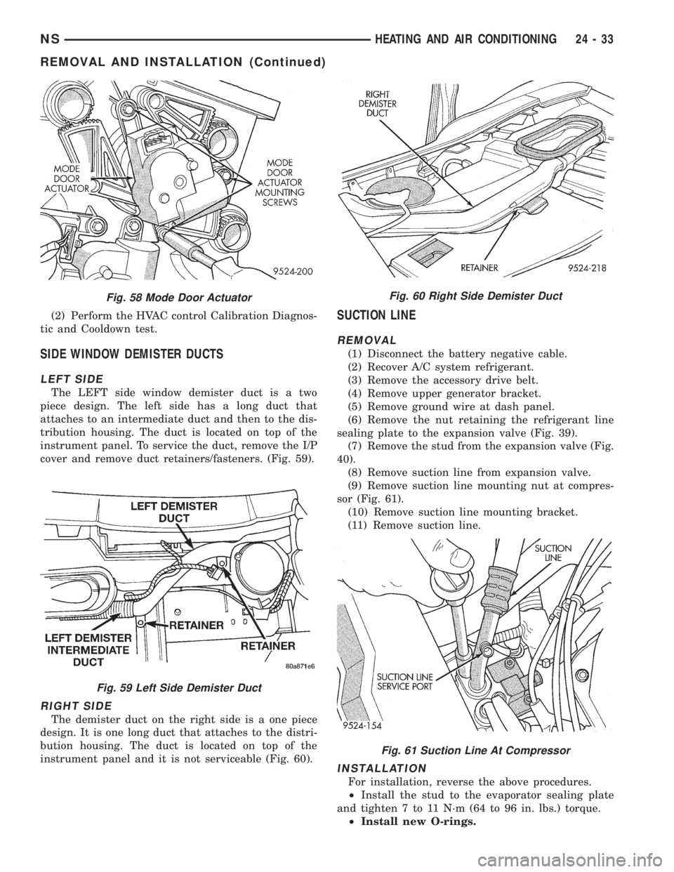
(2) Perform the HVAC control Calibration Diagnos-
tic and Cooldown test.
SIDE WINDOW DEMISTER DUCTS
LEFT SIDE
The LEFT side window demister duct is a two
piece design. The left side has a long duct that
attaches to an intermediate duct and then to the dis-
tribution housing. The duct is located on top of the
instrument panel. To service the duct, remove the I/P
cover and remove duct retainers/fasteners. (Fig. 59).
RIGHT SIDE
The demister duct on the right side is a one piece
design. It is one long duct that attaches to the distri-
bution housing. The duct is located on top of the
instrument panel and it is not serviceable (Fig. 60).
SUCTION LINE
REMOVAL
(1) Disconnect the battery negative cable.
(2) Recover A/C system refrigerant.
(3) Remove the accessory drive belt.
(4) Remove upper generator bracket.
(5) Remove ground wire at dash panel.
(6) Remove the nut retaining the refrigerant line
sealing plate to the expansion valve (Fig. 39).
(7) Remove the stud from the expansion valve (Fig.
40).
(8) Remove suction line from expansion valve.
(9) Remove suction line mounting nut at compres-
sor (Fig. 61).
(10) Remove suction line mounting bracket.
(11) Remove suction line.
INSTALLATION
For installation, reverse the above procedures.
²Install the stud to the evaporator sealing plate
and tighten 7 to 11 N´m (64 to 96 in. lbs.) torque.
²Install new O-rings.
Fig. 58 Mode Door Actuator
Fig. 59 Left Side Demister Duct
Fig. 60 Right Side Demister Duct
Fig. 61 Suction Line At Compressor
NSHEATING AND AIR CONDITIONING 24 - 33
REMOVAL AND INSTALLATION (Continued)
Page 1867 of 1938
HEATING AND AIR CONDITIONING
CONTENTS
page page
GENERAL INFORMATION
INTRODUCTION........................ 1
SAFETY PRECAUTIONS AND WARNINGS.... 2
DESCRIPTION AND OPERATION
A/C PRESSURE TRANSDUCER............ 2
A/C SERVICE PORTS.................... 2
AIR DISTRIBUTION DUCTS............... 2
COMPRESSOR......................... 2
COMPRESSOR HIGH-PRESSURE RELIEF
VALVE .............................. 3
CONDENSATE DRAIN.................... 3
ENGINE COOLING SYSTEM REQUIREMENTS . 3
EVAPORATOR PROBE................... 3
HANDLING TUBING AND FITTINGS........ 3
HVAC CONTROL MODULE................ 3
SIDE DOOR HEATER A/C OUTLETS........ 4
SIDE WINDOW DEMISTER............... 4
SYSTEM AIRFLOW..................... 4
SYSTEM OIL LEVEL..................... 4
DIAGNOSIS AND TESTING
A/C PERFORMANCE TEST............... 11
A/C PRESSURE TRANSDUCER........... 11
ACTUATOR CALIBRATION/DIAGNOSTICS AND
COOLDOWN TEST..................... 5
BLOWER MOTOR AND WHEEL ASSEMBLY . 12
COMPRESSOR CLUTCH/COIL............ 12
COMPRESSOR NOISE DIAGNOSIS........ 12
EXPANSION VALVE.................... 14
HEATER PERFORMANCE TEST........... 14
HVAC CONTROL DIAGNOSTIC CONDITIONS . 9
SYSTEM CHARGE LEVEL TEST........... 15SERVICE PROCEDURES
CHARGING REFRIGERANT SYSTEM....... 17
EVACUATING REFRIGERANT SYSTEM..... 17
R-134a REFRIGERANT.................. 16
STICKING HVAC CONTROL MODULE PUSH
BUTTONS.......................... 18
SYSTEM LEAK CHECKING............... 19
THERMOCOUPLE PROBE............... 18
REMOVAL AND INSTALLATION
A/C PRESSURE TRANSDUCER........... 19
A/C SERVICE PORTS................... 19
BLEND-AIR DOOR ACTUATOR........... 20
BLOWER MOTOR AND WHEEL ASSEMBLY . 20
BLOWER MOTOR RESISTOR BLOCK...... 21
BLOWER MOTOR WHEEL............... 22
COMPRESSOR (2.5L TURBO DIESEL)..... 22
CONDENSER ASSEMBLY................ 23
DISCHARGE LINE..................... 23
EVAPORATOR PROBE.................. 24
EXPANSION VALVE.................... 25
FILTER-DRIER ASSEMBLY............... 26
HEATER A/C UNIT HOUSING............. 26
HEATER CORE........................ 26
HEATER HOSES....................... 28
LIQUID LINE......................... 28
MODE DOOR ACTUATOR................ 29
RECIRC DOOR ACTUATOR.............. 30
SIDE WINDOW DEMISTER DUCTS........ 29
SUCTION LINE........................ 29
DISASSEMBLY AND ASSEMBLY
HEATER A/C UNIT RECONDITION......... 30
GENERAL INFORMATION
INTRODUCTION
The Heater, or Heater and Air Conditioning sys-
tems share many of the same components. This
group will deal with both systems together when
component function is common, and separately when
they are not.
For proper operation of the instrument panel con-
trols, refer to the Owner's Manual provided with the
vehicle.All vehicles are equipped with a common Heater
A/C unit housing assembly. When the vehicle has
only a heater system, the evaporator and recirculat-
ing air door are omitted.
An optional zone control HVAC unit is available.
This unit has dual blend-air doors that can be regu-
lated independently of each other. The temperature
setting can be different from driver's side to passen-
ger side.
NS/GSHEATING AND AIR CONDITIONING 24 - 1