fuse diagram CHRYSLER VOYAGER 2001 User Guide
[x] Cancel search | Manufacturer: CHRYSLER, Model Year: 2001, Model line: VOYAGER, Model: CHRYSLER VOYAGER 2001Pages: 4284, PDF Size: 83.53 MB
Page 445 of 4284

Symptom:
*NO RESPONSE FROM RADIO
POSSIBLE CAUSES
NO RESPONSE FROM RADIO
OPEN FUSED ACCESSORY RELAY OUTPUT CIRCUIT
OPEN FUSED B+ CIRCUIT
RADIO GROUND CIRCUIT OPEN
OPEN PCI BUS CIRCUIT
RADIO
TEST ACTION APPLICABILITY
1 Turn the ignition on.
Note: As soon as one or more module communicates with the DRB, answer
the question.
With the DRB, attempt to communicate with the Airbag Control Module (ACM).
With the DRB, attempt to communicate with the Body Control Module (BCM).
Was the DRB able to I/D or establish communications with either of the modules?All
Ye s®Go To 2
No®Refer to the Communications category and perform the symptom
PCI Bus Communication Failure.
Perform BODY VERIFICATION TEST - VER 1.
2 Turn the ignition off.
Disconnect the Radio C1 harness connector.
Turn the ignition on.
Using a 12-volt test light connected to ground, probe the Fused Accessory Relay
Output circuit.
Is the test light illuminated?All
Ye s®Go To 3
No®Check fuse #5 in the IPM for an open. If ok, repair the Fused
Accessory Relay Output circuit for an open or short. Refer to the
wiring diagrams located in the Service Information.
Perform BODY VERIFICATION TEST - VER 1.
3 Turn the ignition off.
Disconnect the Radio C1 harness connector.
Using a 12-volt test light connected to ground, probe the Fused B+ circuit.
Is the test light illuminated?All
Ye s®Go To 4
No®Check fuse #14 in the IPM for an open. If ok, repair the Fused B+
circuit for an open or short. Refer to the wiring diagrams located
in the Service Information.
Perform BODY VERIFICATION TEST - VER 1.
416
COMMUNICATION
Page 449 of 4284

Symptom:
*NO RESPONSE FROM TRANSMISSION CONTROL MODULE
POSSIBLE CAUSES
NO RESPONSE FROM TRANSMISSION CONTROL MODULE
FCM OUTPUT (RUN/ST) CIRCUIT OPEN
IGNITION SWITCH OUTPUT (START) CIRCUIT OPEN
FUSED B(+) CIRCUIT OPEN
GROUND CIRCUIT(S) OPEN
OPEN PCI BUS CIRCUIT
TRANSMISSION CONTROL MODULE
TEST ACTION APPLICABILITY
1 Turn the ignition on.
Note: As soon as one or more module communicates with the DRB, answer
the question.
With the DRB, attempt to communicate with the Airbag Control Module (ACM).
With the DRB, attempt to communicate with the Body Control Module (BCM).
Was the DRB able to I/D or establish communications with either of the modules?All
Ye s®Go To 2
No®Refer to the Body Communication category and perform the
symptom PCI Bus Communication Failure.
Perform 41TE TRANSMISSION VERIFICATION TEST - VER 1.
2 Turn the ignition off.
Disconnect the TCM harness connector.
Turn the ignition on.
Using a 12-volt test light connected to ground, probe the FCM Output (Run/St)
circuit.
Note: The light must illuminate brightly, if it does not light, or lights dimly,
the circuit must be repaired. If there is any doubt, compare the brightness
when testing the circuit, to the brightness when connected directly to the
battery positive post.
Is the test light illuminated?All
Ye s®Go To 3
No®Repair the FCM Output (Run/St) circuit for an open. Refer to the
wiring diagrams location in the Service Information.
Perform 41TE TRANSMISSION VERIFICATION TEST - VER 1.
420
COMMUNICATION
Page 450 of 4284

TEST ACTION APPLICABILITY
3 Turn the ignition off.
Disconnect the TCM harness connector.
Remove the starter relay from the IPM.
Using a 12-volt test light connected to ground, probe the Ignition Switch Output
(Start) circuit.
Note: The light must illuminate brightly, if it does not light, or lights dimly,
the circuit must be repaired. If there is any doubt, compare the brightness
when testing the circuit, to the brightness when connected directly to the
battery positive post.
Observe the test light while momentarily turning the ignition switch to the Start
position.
Is the test light illuminated?All
Ye s®Go To 4
No®Repair the Ignition Switch Output (Start) circuit for an open.
Refer to the wiring diagrams located in the Service Information.
Perform 41TE TRANSMISSION VERIFICATION TEST - VER 1.
Note: Reinstall the original Starter Relay.
4 Turn the ignition off.
Disconnect the TCM harness connector.
Using a 12-volt test light connected to ground, probe the Fused B(+) circuit.
Note: The light must illuminate brightly, if it does not light, or lights dimly,
the circuit must be repaired. If there is any doubt, compare the brightness
when testing the circuit, to the brightness when connected directly to the
battery positive post.
Is the test light illuminated?All
Ye s®Go To 5
No®Check IPM fuse #15 for an open. If OK, repair the Fused B(+)
circuit for an open. Refer to the wiring diagrams located in the
Service Information.
Perform 41TE TRANSMISSION VERIFICATION TEST - VER 1.
5 Turn the ignition off.
Disconnect the TCM harness connector.
Using a 12-volt test light connected to 12-volts, probe each ground circuit in the TCM
connector.
NOTE: The light must illuminate brightly, if it does not light, or lights dimly,
the circuit must be repaired. If there is any doubt, compare the brightness
when testing the circuit, to the brightness when connected directly to the
battery negative post.
Is the light illuminated at all ground circuits?All
Ye s®Go To 6
No®Repair the Ground circuit(s) for an open. Check the main ground
connection to engine block and/or chassis. Refer to the wiring
diagrams located in the Service Information.
Perform 41TE TRANSMISSION VERIFICATION TEST - VER 1.
421
COMMUNICATION
*NO RESPONSE FROM TRANSMISSION CONTROL MODULE ÐContinued
Page 656 of 4284

Symptom:
IGN RUN/START INPUT WIRING
When Monitored and Set Condition:
IGN RUN/START INPUT WIRING
When Monitored: With the ignition on and battery voltage greater than 10.4 volts.
Set Condition: The Fused Ignition Switch Output circuit voltage at the FCM goes below
0.5 volts.
POSSIBLE CAUSES
TEST FOR CURRENT DTC'S
FRONT CONTROL MODULE INTERNAL MALFUNCTION
FUSE AND RELAY CENTER INTERNAL MALFUNCTION
FUSED IGNITION SWITCH OUTPUT CIRCUIT OPEN
TEST ACTION APPLICABILITY
1 With the DRBIIIt, record and erase the current Front Control Module DTC's.
Cycle the ignition from ON to OFF.
Start the vehicle and observe the DRBIIIt.
With the DRBIIIt, read DTC's.
Does the DRBIIItdisplay: IGNITION RUN-START INPUT WIRING?All
Ye s®Go To 2
No®The condition that caused this DTC is currently not present. Use
the wiring diagram/schematic as a guide, and inspect the related
wiring harness for a possible intermittent condition.
Perform BODY VERIFICATION TEST - VER 1.
2 Turn the ignition off.
Disconnect the Front Control Module from the Fuse and Relay Center.
Measure the voltage of the Fused Ignition Switch Output circuit (cavity 37) at the
Fuse and Relay Center side of the FCM connector.
Turn the ignition on.
Is the voltage above 10.0 volts?All
Ye s®Replace the Front Control Module.
Perform BODY VERIFICATION TEST - VER 1.
No®Go To 3
627
INTELLIGENT POWER MODULE
Page 658 of 4284

Symptom:
IGNITION START INPUT WIRING
When Monitored and Set Condition:
IGNITION START INPUT WIRING
When Monitored: With the ignition on and battery voltage greater than 10.4 volts.
Set Condition: The Fused Ignition Switch Output (Start) circuit voltage at the FCM goes
below 0.5 volts.
POSSIBLE CAUSES
TEST FOR CURRENT DTC'S
FRONT CONTROL MODULE INTERNAL MALFUNCTION
FUSE AND RELAY CENTER INTERNAL MALFUNCTION
FUSED IGNITION SWITCH OUTPUT CIRCUIT OPEN
TEST ACTION APPLICABILITY
1 With the DRBIIIt, record and erase the current Front Control Module DTC's.
Cycle the ignition from ON to OFF.
Start the vehicle and observe the DRBIIIt.
With the DRBIIIt, read DTC's.
Does the DRBIIItdisplay: IGNITION START INPUT WIRING?All
Ye s®Go To 2
No®The condition that caused this DTC is currently not present. Use
the wiring diagram/schematic as a guide, and inspect the related
wiring harness for a possible intermittent condition.
Perform BODY VERIFICATION TEST - VER 1.
2 Turn the ignition off.
Disconnect the Front Control Module from the Fuse and Relay Center.
Measure the voltage of the Fused Ignition Switch Output circuit (cavity 37) at the
Fuse and Relay Center side of the FCM connector.
Turn the ignition on.
Is the voltage above 10.0 volts?All
Ye s®Replace the Front Control Module.
Perform BODY VERIFICATION TEST - VER 1.
No®Go To 3
629
INTELLIGENT POWER MODULE
Page 939 of 4284

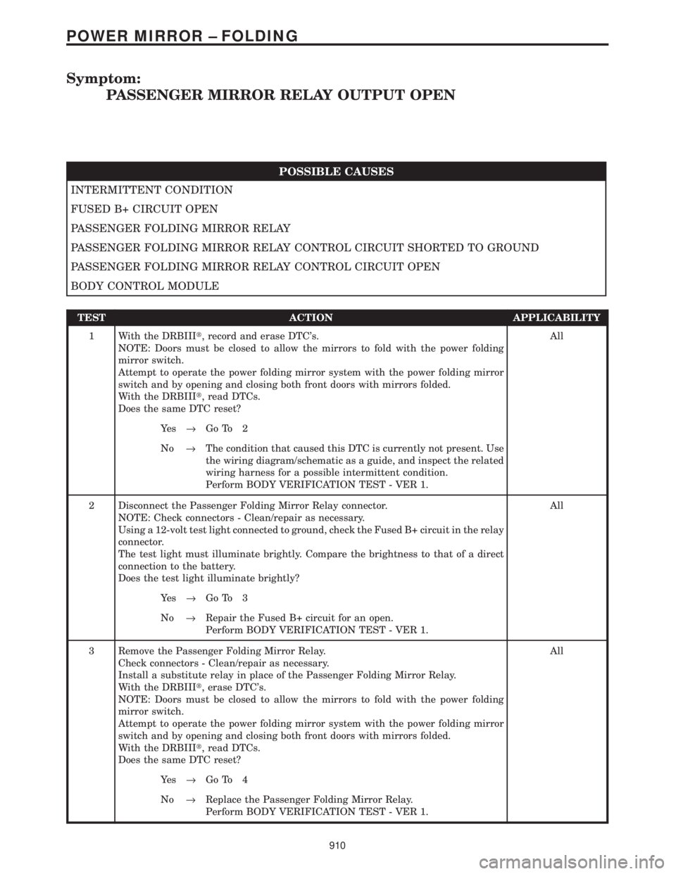
Symptom:
PASSENGER MIRROR RELAY OUTPUT OPEN
POSSIBLE CAUSES
INTERMITTENT CONDITION
FUSED B+ CIRCUIT OPEN
PASSENGER FOLDING MIRROR RELAY
PASSENGER FOLDING MIRROR RELAY CONTROL CIRCUIT SHORTED TO GROUND
PASSENGER FOLDING MIRROR RELAY CONTROL CIRCUIT OPEN
BODY CONTROL MODULE
TEST ACTION APPLICABILITY
1 With the DRBIIIt, record and erase DTC's.
NOTE: Doors must be closed to allow the mirrors to fold with the power folding
mirror switch.
Attempt to operate the power folding mirror system with the power folding mirror
switch and by opening and closing both front doors with mirrors folded.
With the DRBIIIt, read DTCs.
Does the same DTC reset?All
Ye s®Go To 2
No®The condition that caused this DTC is currently not present. Use
the wiring diagram/schematic as a guide, and inspect the related
wiring harness for a possible intermittent condition.
Perform BODY VERIFICATION TEST - VER 1.
2 Disconnect the Passenger Folding Mirror Relay connector.
NOTE: Check connectors - Clean/repair as necessary.
Using a 12-volt test light connected to ground, check the Fused B+ circuit in the relay
connector.
The test light must illuminate brightly. Compare the brightness to that of a direct
connection to the battery.
Does the test light illuminate brightly?All
Ye s®Go To 3
No®Repair the Fused B+ circuit for an open.
Perform BODY VERIFICATION TEST - VER 1.
3 Remove the Passenger Folding Mirror Relay.
Check connectors - Clean/repair as necessary.
Install a substitute relay in place of the Passenger Folding Mirror Relay.
With the DRBIIIt, erase DTC's.
NOTE: Doors must be closed to allow the mirrors to fold with the power folding
mirror switch.
Attempt to operate the power folding mirror system with the power folding mirror
switch and by opening and closing both front doors with mirrors folded.
With the DRBIIIt, read DTCs.
Does the same DTC reset?All
Ye s®Go To 4
No®Replace the Passenger Folding Mirror Relay.
Perform BODY VERIFICATION TEST - VER 1.
910
POWER MIRROR ± FOLDING
Page 1157 of 4284

TABLE OF CONTENTS - Continued
RIGHT REAR WHEEL SPEED SIGNAL FAILURE.............................26
SYSTEM OVERVOLTAGE................................................28
SYSTEM UNDERVOLTAGE...............................................30
VALVE POWER FEED FAILURE...........................................32
*BRAKE LAMP SWITCH..................................................35
*TRAC OFF INDICATOR NEVER/ALWAYS ON...............................36
*TRAC ON INDICATOR NEVER/ALWAYS ON................................39
VERIFICATION TESTS
VERIFICATION TESTS...................................................40
8.0 COMPONENT LOCATIONS...............................................41
8.1CONTROLLER ANTILOCK BRAKE (CAB)..............................41
8.2DATA LINK CONNECTOR...........................................41
8.3FUSES...........................................................42
8.4TRACTION CONTROL SWITCH......................................42
8.4.1TRACTION CONTROL INDICATORS...........................43
8.5WHEEL SPEED SENSORS..........................................43
8.5.1FRONT....................................................43
8.5.2REAR.....................................................44
8.5AWHEEL SPEED SENSOR CONNECTORS..............................44
8.5A.1FRONT....................................................44
8.5A.2REAR.....................................................45
8.6BRAKE LAMP SWITCH.............................................45
9.0 CONNECTOR PINOUTS.................................................47
CONTROLLER ANTILOCK BRAKE - BLACK 24 WAY..........................47
DATA LINK CONNECTOR - WHITE 16 WAY.................................47
DIAGNOSTIC JUNCTION PORT - BLACK 16 WAY............................48
INTELLIGENT POWER MODULE C4 - GRAY 10 WAY.........................48
LEFT FRONT WHEEL SPEED SENSOR - BLACK 2 WAY......................48
LEFT FRONT WHEEL SPEED SENSOR CONNECTOR (SENSOR SIDE)-2WAY..49
LEFT REAR WHEEL SPEED SENSOR - BLACK 2 WAY........................49
LEFT REAR WHEEL SPEED SENSOR CONNECTOR (SENSOR SIDE)-2WAY ...49
FUSES (IPM)...........................................................51
PUMP MOTOR CONNECTOR-2WAY.....................................52
RIGHT FRONT WHEEL SPEED SENSOR - GRAY 2 WAY......................52
RIGHT FRONT WHEEL SPEED SENSOR CONNECTOR
(SENSOR SIDE)-2WAY.................................................52
RIGHT REAR WHEEL SPEED SENSOR - BLACK 2 WAY......................52
RIGHT REAR WHEEL SPEED SENSOR CONNECTOR (SENSOR SIDE)-2WAY..53
TRACTION CONTROL SWITCH - BLACK 2 WAY.............................53
10.0 SCHEMATIC DIAGRAMS.................................................55
TEVES MARK 20 ANTILOCK BRAKE SYSTEM........................55
ii
Page 1812 of 4284

(4) Connect battery negative cable.
QUARTER PANEL SPEAKER
REMOVAL
(1) Disconnect and isolate the battery negative
cable.
(2) Remove speaker grill by prying away from trim
panel.
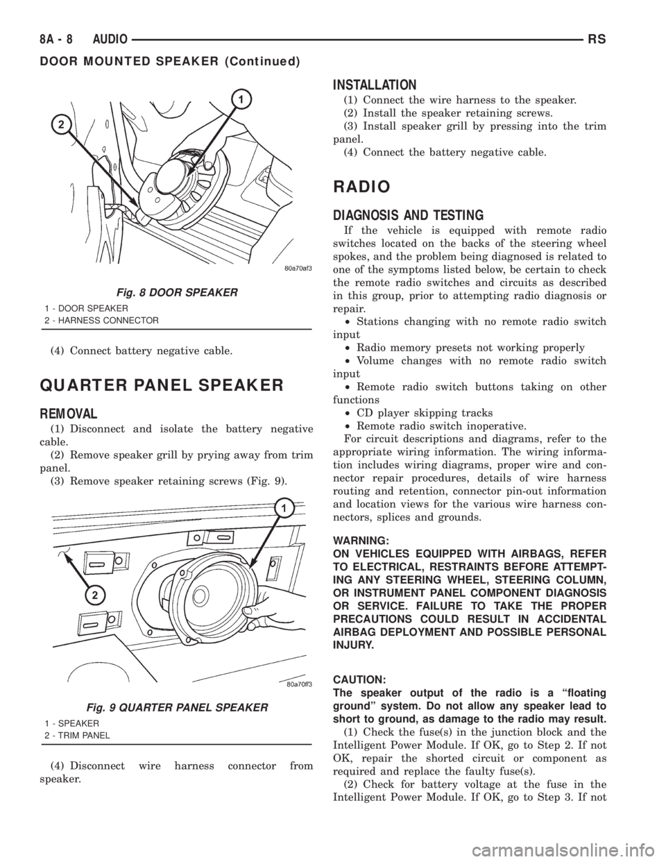
(3) Remove speaker retaining screws (Fig. 9).
(4) Disconnect wire harness connector from
speaker.
INSTALLATION
(1) Connect the wire harness to the speaker.
(2) Install the speaker retaining screws.
(3) Install speaker grill by pressing into the trim
panel.
(4) Connect the battery negative cable.
RADIO
DIAGNOSIS AND TESTING
If the vehicle is equipped with remote radio
switches located on the backs of the steering wheel
spokes, and the problem being diagnosed is related to
one of the symptoms listed below, be certain to check
the remote radio switches and circuits as described
in this group, prior to attempting radio diagnosis or
repair.
²Stations changing with no remote radio switch
input
²Radio memory presets not working properly
²Volume changes with no remote radio switch
input
²Remote radio switch buttons taking on other
functions
²CD player skipping tracks
²Remote radio switch inoperative.
For circuit descriptions and diagrams, refer to the
appropriate wiring information. The wiring informa-
tion includes wiring diagrams, proper wire and con-
nector repair procedures, details of wire harness
routing and retention, connector pin-out information
and location views for the various wire harness con-
nectors, splices and grounds.
WARNING:
ON VEHICLES EQUIPPED WITH AIRBAGS, REFER
TO ELECTRICAL, RESTRAINTS BEFORE ATTEMPT-
ING ANY STEERING WHEEL, STEERING COLUMN,
OR INSTRUMENT PANEL COMPONENT DIAGNOSIS
OR SERVICE. FAILURE TO TAKE THE PROPER
PRECAUTIONS COULD RESULT IN ACCIDENTAL
AIRBAG DEPLOYMENT AND POSSIBLE PERSONAL
INJURY.
CAUTION:
The speaker output of the radio is a ªfloating
groundº system. Do not allow any speaker lead to
short to ground, as damage to the radio may result.
(1) Check the fuse(s) in the junction block and the
Intelligent Power Module. If OK, go to Step 2. If not
OK, repair the shorted circuit or component as
required and replace the faulty fuse(s).
(2) Check for battery voltage at the fuse in the
Intelligent Power Module. If OK, go to Step 3. If not
Fig. 8 DOOR SPEAKER
1 - DOOR SPEAKER
2 - HARNESS CONNECTOR
Fig. 9 QUARTER PANEL SPEAKER
1 - SPEAKER
2 - TRIM PANEL
8A - 8 AUDIORS
DOOR MOUNTED SPEAKER (Continued)
Page 1898 of 4284

OPERATION
The Rear Window Defogger (Fig. 1) system consists
of two vertical bus bars linked by a series of grid
lines on the inside surface of the rear window. The
electrical circuit consists of the rear defogger switch
in the HVAC control assembly and a relay with timer
switch to turn OFF the system after ten minutes.
The main feed circuit is protected by fuse 13 (40
amp) in the Power Distribution Center (PDC) which
is integrated as a unit call Integrated Power Module
(IPM). The rear defogger switch and relay also acti-
vates the heated power side view mirrors and heated
windshield wiper de-icer. The heated windshield
wiper de-icer is powered by the RUN/ACC relay in
the IPM and feed thru fuse #11 (20 amp) in the PDC.
The heated mirror circuit is protected by a non-servi-
cable Positive Temperature Coefficient (PTC) located
inside the PDC. The heated windshield wiper de-icer
circuit is protected by fuse 11 (20 amp) in the PDC.
The Heated Windshield Wiper Deicer is also acti-
vated when the DEFROST mode is selected on the
HVAC. In the DEFROST mode the rear defogger
relay/timer is bypassed, the heated windshield wiper
de-icer will stay ON until the another mode is
selected. For circuit information and component loca-
tion refer to appropriate section for Wiring Diagrams.
CAUTION:
Since grid lines can be damaged or scraped off
with sharp instruments, care should be taken in
cleaning the glass or removing foreign materials,
decals or stickers. Normal glass cleaning solvents
or hot water used with rags or toweling is recom-
mended.
DEFOGGER RELAY
DESCRIPTION
There is no heated glass relay it is integrated into
the (E.B.L) relay that is located in the IPM in the
engine compartment.
REAR WINDOW DEFOGGER
GRID
STANDARD PROCEDURE - GRID LINE
REPAIR-REAR
For Grid repair procedure for the rear window
defogger (Refer to 8 - ELECTRICAL/HEATED
GLASS/WINDSHIELD GRID - STANDARD PROCE-
DURE).
REAR WINDOW DEFOGGER
SWITCH
DESCRIPTION
The rear window defogger switch is integrated into
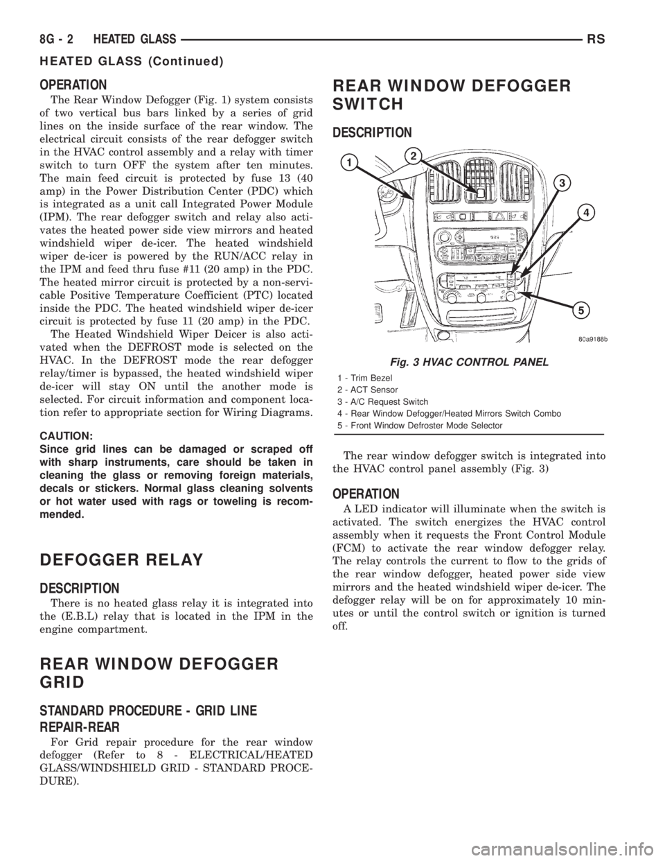
the HVAC control panel assembly (Fig. 3)
OPERATION
A LED indicator will illuminate when the switch is
activated. The switch energizes the HVAC control
assembly when it requests the Front Control Module
(FCM) to activate the rear window defogger relay.
The relay controls the current to flow to the grids of
the rear window defogger, heated power side view
mirrors and the heated windshield wiper de-icer. The
defogger relay will be on for approximately 10 min-
utes or until the control switch or ignition is turned
off.
Fig. 3 HVAC CONTROL PANEL
1 - Trim Bezel
2 - ACT Sensor
3 - A/C Request Switch
4 - Rear Window Defogger/Heated Mirrors Switch Combo
5 - Front Window Defroster Mode Selector
8G - 2 HEATED GLASSRS
HEATED GLASS (Continued)
Page 1899 of 4284

WINDSHIELD GRID
DIAGNOSIS AND TESTING - SYSTEM TEST
Electrically heated rear window defogger or the
heated windshield wiper deicer operation can be
checked on the vehicle in the following manner:
(1) Turn the ignition switch to the ON position.
(2) Using a ammeter on the battery, turn the rear
defogger control switch to the ON position, a distinct
increase in amperage draw should be noted.
(3) The rear window defogger or the heated wind-
shield wiper deicer operation can be checked by feel-
ing the glass. A distinct difference in temperature
between the grid lines and adjacent clear glass can
be detected in 3 to 4 minutes of operation.
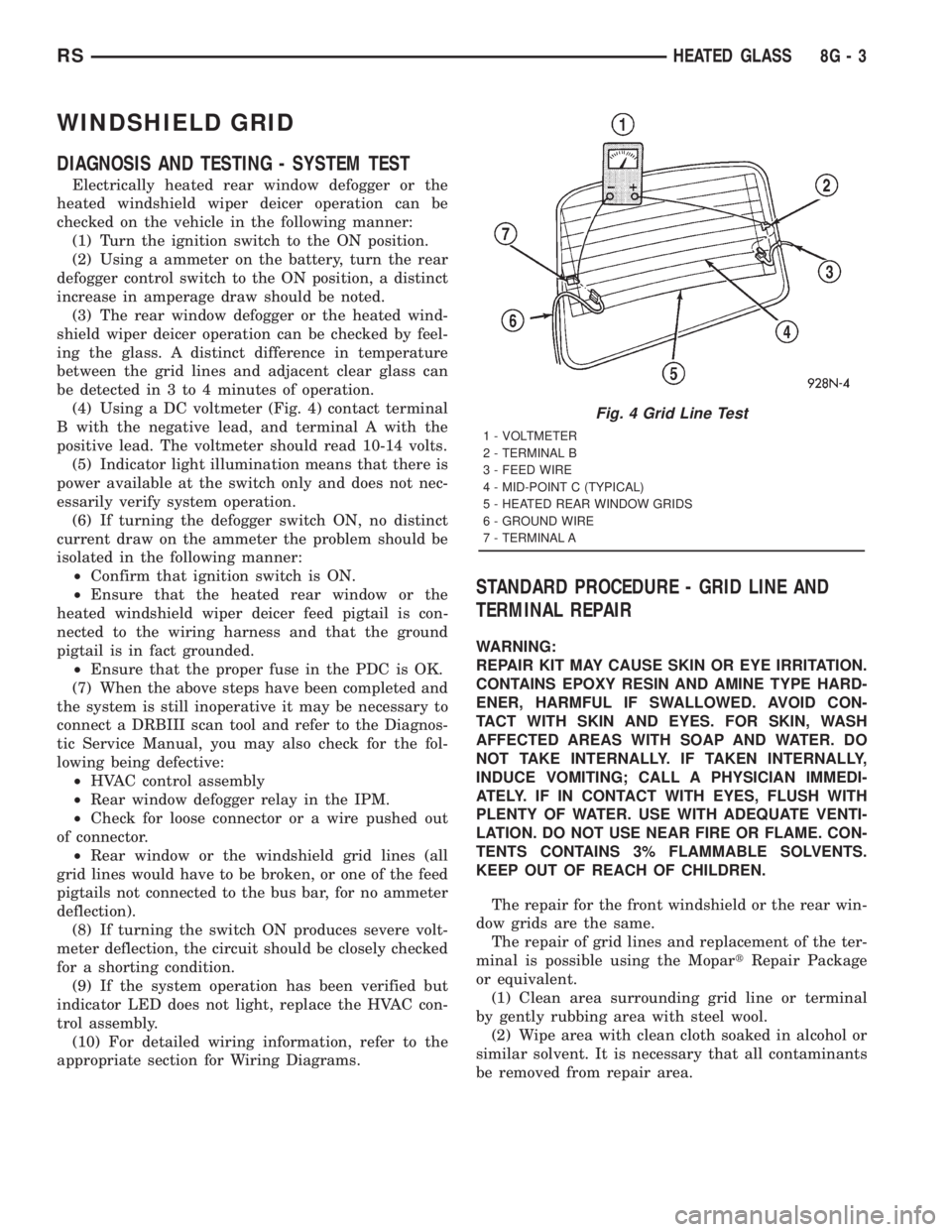
(4) Using a DC voltmeter (Fig. 4) contact terminal
B with the negative lead, and terminal A with the
positive lead. The voltmeter should read 10-14 volts.
(5) Indicator light illumination means that there is
power available at the switch only and does not nec-
essarily verify system operation.
(6) If turning the defogger switch ON, no distinct
current draw on the ammeter the problem should be
isolated in the following manner:
²Confirm that ignition switch is ON.
²Ensure that the heated rear window or the
heated windshield wiper deicer feed pigtail is con-
nected to the wiring harness and that the ground
pigtail is in fact grounded.
²Ensure that the proper fuse in the PDC is OK.
(7) When the above steps have been completed and
the system is still inoperative it may be necessary to
connect a DRBIII scan tool and refer to the Diagnos-
tic Service Manual, you may also check for the fol-
lowing being defective:
²HVAC control assembly
²Rear window defogger relay in the IPM.
²Check for loose connector or a wire pushed out
of connector.
²Rear window or the windshield grid lines (all
grid lines would have to be broken, or one of the feed
pigtails not connected to the bus bar, for no ammeter
deflection).
(8) If turning the switch ON produces severe volt-
meter deflection, the circuit should be closely checked
for a shorting condition.
(9) If the system operation has been verified but
indicator LED does not light, replace the HVAC con-
trol assembly.
(10) For detailed wiring information, refer to the
appropriate section for Wiring Diagrams.
STANDARD PROCEDURE - GRID LINE AND
TERMINAL REPAIR
WARNING:
REPAIR KIT MAY CAUSE SKIN OR EYE IRRITATION.
CONTAINS EPOXY RESIN AND AMINE TYPE HARD-
ENER, HARMFUL IF SWALLOWED. AVOID CON-
TACT WITH SKIN AND EYES. FOR SKIN, WASH
AFFECTED AREAS WITH SOAP AND WATER. DO
NOT TAKE INTERNALLY. IF TAKEN INTERNALLY,
INDUCE VOMITING; CALL A PHYSICIAN IMMEDI-
ATELY. IF IN CONTACT WITH EYES, FLUSH WITH
PLENTY OF WATER. USE WITH ADEQUATE VENTI-
LATION. DO NOT USE NEAR FIRE OR FLAME. CON-
TENTS CONTAINS 3% FLAMMABLE SOLVENTS.
KEEP OUT OF REACH OF CHILDREN.
The repair for the front windshield or the rear win-
dow grids are the same.
The repair of grid lines and replacement of the ter-
minal is possible using the MopartRepair Package
or equivalent.
(1) Clean area surrounding grid line or terminal
by gently rubbing area with steel wool.
(2) Wipe area with clean cloth soaked in alcohol or
similar solvent. It is necessary that all contaminants
be removed from repair area.
Fig. 4 Grid Line Test
1 - VOLTMETER
2 - TERMINAL B
3 - FEED WIRE
4 - MID-POINT C (TYPICAL)
5 - HEATED REAR WINDOW GRIDS
6 - GROUND WIRE
7 - TERMINAL A
RSHEATED GLASS8G-3