rear view CHRYSLER VOYAGER 2001 Service Manual
[x] Cancel search | Manufacturer: CHRYSLER, Model Year: 2001, Model line: VOYAGER, Model: CHRYSLER VOYAGER 2001Pages: 4284, PDF Size: 83.53 MB
Page 55 of 4284
manual sliding door. When the child lock out switch
is on, the B pillar switches are disabled.
There is only one part number for the power
sliding door module (PSDM). The driver sliding
door harness has an additional ground circuit which
will identify it as the driver side. This eliminates
the need for a left and a right side module.
3.18.2 DIAGNOSTIC FEATURES
The PSDM can be flashed on vehicle via PCI bus
with a DRBIIItdiagnostic tool. The DRBIIItcan
read all inputs, actuate all outputs, read module
information, and read diagnostic trouble codes. As a
reminder, some DTC's can be set during normal
PSD operation.
3.18.3 SYSTEM INHIBITORS
1. Battery voltage too high or too low (above 16V,
below 9.5V)
2. Vehicle in gear
3. Vehicle speed > 0 mph/km/h
4. Child locks enabled inhibit the B pillar switch
operation
5. O/H console lockout will inhibit the B pillar
switches
6. Doors locked will inhibit all interior switches
from opening (Overhead Console, B Pillar). A
locked sliding door can be power closed.
3.19 REAR WINDOW DEFOG/HEATED
MIRROR/FRONT WIPER DE-ICE
The defroster button located on the HVAC control
controls the rear window defogger, heated side view
mirrors and front wiper de-icer grid. In addition the
front wiper de-ice function is turned on when front
defog/defrost mode is selected.
When the defroster button is pushed, the HVAC
control sends a bus message over the PCI bus to the
Front Control Module (FCM) which controls the
Rear Window Defogger relay. The defroster LED
will illuminate when the defroster function is on.
The defroster will function for 10 minutes or can be
cycled off sooner by pressing the defroster button
again. The front wiper de-icer grid receives its 12
volts from the accessory relay through fuse 11 and
the HVAC control module supplies the grid ground.
3.20 VEHICLE THEFT SECURITY SYSTEM
3.20.1 BASE ALARM SYSTEM
The Vehicle Theft Security System (VTSS) is part
of the Body Control Module (BCM). The BCM
monitors the vehicle doors, liftgate, hood, and theignition for unauthorized operation. The alarm ac-
tivates by sounding the horn, flashing the head-
lamps and the VTSS indicator lamp. The VTSS does
not prevent engine operation, this is done with the
Sentry Key Immobilizer Module (SKIM). Passive
arming occurs in one of two ways. Upon normal
vehicle exit by removing the ignition key, opening
the driver door, locking the doors with the power
lock, and closing the driver door, or by removing the
ignition key, opening the driver door, closing the
driver door, and locking the doors with the Remote
Keyless Entry (RKE) transmitter. The VTSS indi-
cator lamp will flash for approximately 15 seconds
during the arming process. If there is no interrup-
tion during the arming process, upon completion
the VTSS indicator lamp will flash at a slower rate.
When the BCM receives an input to trigger the
alarm, the BCM will control the outputs of the
headlamps, horn, and VTSS lamp for approxi-
mately 18 minutes.
Arming (Active and Passive)
Active arming occurs when the RKE transmitter
is used to lock the vehicle doors, whether the doors
are open or closed. The arming process is complete
only after all doors are closed.
Passive arming occurs when the ignition key is
removed, the driver door is opened, and the doors
are locked with the power door lock switch, and the
door is closed.
Disarming (Active and Passive)
Active disarming occurs when the RKE transmit-
ter is used to unlock the vehicle doors. This disarm-
ing will also halt the alarm once it has been acti-
vated.
Passive disarming occurs upon normal vehicle
entry (unlocking driver door with the key). This
disarming will also halt the alarm once it has been
activated.
Tamper Alert
The VTSS tamper alert will sound the horn three
times upon disarming to indicate a tamper condi-
tion has occurred.
Manual Override
The system will not arm if the doors are locked
using the manual lock control or if the locks are
actuated by an inside occupant after the doors are
closed.
Diagnosis
For complaints about the Vehicle Theft Alarm
triggering on its own, use the DRBIIItand read the
Last VTSS Cause status.
26
GENERAL INFORMATION
Page 59 of 4284
WARNING: BEFORE ROAD TESTING A
VEHICLE, BE SURE THAT ALL
COMPONENTS ARE REASSEMBLED.
DURING THE TEST DRIVE, DO NOT TRY TO
READ THE DRBIIITSCREEN WHILE IN
MOTION. DO NOT HANG THE DRBIIITFROM
THE REAR VIEW MIRROR OR OPERATE IT
YOURSELF. HAVE AN ASSISTANT
AVAILABLE TO OPERATE THE DRBIIIT.
5.0 REQUIRED TOOLS AND
EQUIPMENT
DRBIIIt(diagnostic read-out box)
Jumper wires
Ohmmeter
Voltmeter
Sentry Key Tester
Test Light
8310 Airbag System Load Tool
8443 SRS Airbag System Load Tool
Diagnostic Junction Port Tester 8339
6.0 GLOSSARY OF TERMS
ABSantilock brake system
ACMairbag control module
AECMairbag electronic control module
(ACM)
ASDMairbag system diagnostic module
(ACM)
AT Cautomatic temperature control
BCMbody control module
CABcontroller antilock brake
CMTCcompass/mini-trip computer
CPAconnector positive assurance
DABdriver airbag
DCHAdiesel cabin heater assist
(cabin heater)
DLCdata link connector
DTCdiagnostic trouble code
DRdriver
EBLelectric back lite (rear window de-
fogger)ECMEngine control module
EVICelectronic vehicle information center
FCMfront control module
GCCGulf Coast Countries
HVACheater ventilation, air conditioning
IPMintelligent power module
LDUlower drive unit
LHDLeft Hand Drive
MICmechanical instrument cluster
MTCmanual temperature control
MSMMmemory seat/mirror module
OBDon board diagnostics
ODOodometer
ORCoccupant restraint controller
PA Bpassenger airbag
PASSpassenger
PCIProgrammable Communication In-
terface (vehicle communication bus)
PCMpowertrain control module
PDCpower distribution center
PLGpower liftgate
PLGMpower liftgate module
PSDpower sliding door
PSDMpower sliding door module
PWMpulse width modulated
RHDRight Hand Drive
RKEremote keyless entry
SABseat airbag
SBTseat belt tensioner
SIACMside impact airbag control module
SKIMsentry key immobilizer module
SKISsentry key immobilizer system
SQUIBalso called initiator (located inside
airbag)
SRSsupplemental restraint system
TCMtransmission control module
VFDvacuum fluorescent display
VTSSvehicle theft security system
30
GENERAL INFORMATION
Page 220 of 4284
TEST ACTION APPLICABILITY
5 Turn the ignition off.
Disconnect each front and rear speaker harness connector.
Disconnect the Radio C1 and C2 harness connectors.
Measure the resistance between ground and each speaker (-) circuit.
Is the resistance below 1000.0 (1K) ohms?All
Ye s®Repair the speaker (-) circuit for a short to ground.
Perform BODY VERIFICATION TEST - VER 1.
No®Go To 6
6 Turn the ignition off.
Disconnect each front and rear speaker harness connector.
Disconnect the Radio C1 and C2 harness connectors.
Measure the resistance between each speaker (+) circuit and each speaker (-) circuit.
Is the resistance below 1000.0 (1K) ohms for any of the measurements?All
Ye s®Repair the speaker circuits shorted together.
Perform BODY VERIFICATION TEST - VER 1.
No®Go To 7
7 If there are no possible causes remaining, view repair. All
Repair
Replace the Radio.
Perform BODY VERIFICATION TEST - VER 1.
191
AUDIO
ALL OUTPUTS SHORTED ÐContinued
Page 235 of 4284
TEST ACTION APPLICABILITY
6 Turn the ignition off.
Disconnect the Left I/P Speaker harness connector.
Disconnect the Left Front Door Speaker harness connector.
Disconnect the Left Rear Speaker harness connector.
Disconnect the Left Rear Pillar Speaker harness connector (If Equipped).
Disconnect the Radio C1 and C2 harness connectors.
Measure the resistance between ground and each left speaker (+) circuit.
Is the resistance below 1000.0 (1K) ohms?All
Ye s®Repair the left speaker (+) circuit for a short to ground.
Perform BODY VERIFICATION TEST - VER 1.
No®Go To 7
7 Turn the ignition off.
Disconnect the Left I/P Speaker harness connector.
Disconnect the Left Front Door Speaker harness connector.
Disconnect the Left Rear Speaker harness connector.
Disconnect the Left Rear Pillar Speaker harness connector (If Equipped).
Disconnect the Radio C1 and C2 harness connector.
Measure the resistance between ground and each left speaker (-) circuit.
Is the resistance below 1000.0 (1K) ohms?All
Ye s®Repair the left speaker (-) circuit for a short to ground.
Perform BODY VERIFICATION TEST - VER 1.
No®Go To 8
8 Turn the ignition off.
Disconnect the Left I/P Speaker harness connector.
Disconnect the Left Front Door Speaker harness connector.
Disconnect the Left Rear Speaker harness connector.
Disconnect the Left Rear Pillar Speaker harness connector (If Equipped).
Disconnect the Radio C1 and C2 harness connectors.
Measure the resistance between each left speaker (+) circuit and each left speaker (-)
circuit.
Is the resistance below 1000.0 (1K) ohms for any of the measurements?All
Ye s®Repair the left speaker circuits shorted together.
Perform BODY VERIFICATION TEST - VER 1.
No®Go To 9
9 If there are no possible causes remaining, view repair. All
Repair
Replace the Radio.
Perform BODY VERIFICATION TEST - VER 1.
206
AUDIO
LEFT OUTPUT SHORT ÐContinued
Page 245 of 4284
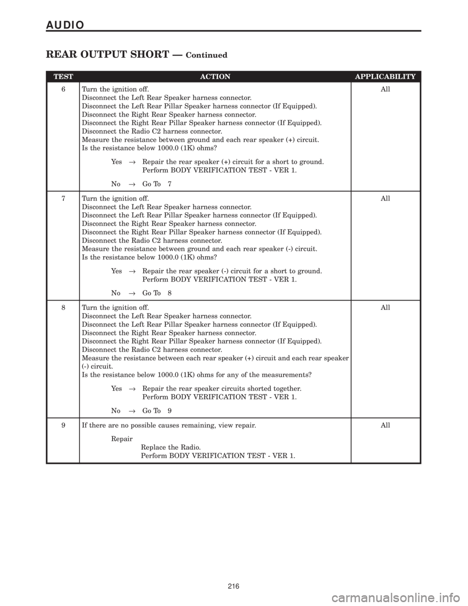
TEST ACTION APPLICABILITY
6 Turn the ignition off.
Disconnect the Left Rear Speaker harness connector.
Disconnect the Left Rear Pillar Speaker harness connector (If Equipped).
Disconnect the Right Rear Speaker harness connector.
Disconnect the Right Rear Pillar Speaker harness connector (If Equipped).
Disconnect the Radio C2 harness connector.
Measure the resistance between ground and each rear speaker (+) circuit.
Is the resistance below 1000.0 (1K) ohms?All
Ye s®Repair the rear speaker (+) circuit for a short to ground.
Perform BODY VERIFICATION TEST - VER 1.
No®Go To 7
7 Turn the ignition off.
Disconnect the Left Rear Speaker harness connector.
Disconnect the Left Rear Pillar Speaker harness connector (If Equipped).
Disconnect the Right Rear Speaker harness connector.
Disconnect the Right Rear Pillar Speaker harness connector (If Equipped).
Disconnect the Radio C2 harness connector.
Measure the resistance between ground and each rear speaker (-) circuit.
Is the resistance below 1000.0 (1K) ohms?All
Ye s®Repair the rear speaker (-) circuit for a short to ground.
Perform BODY VERIFICATION TEST - VER 1.
No®Go To 8
8 Turn the ignition off.
Disconnect the Left Rear Speaker harness connector.
Disconnect the Left Rear Pillar Speaker harness connector (If Equipped).
Disconnect the Right Rear Speaker harness connector.
Disconnect the Right Rear Pillar Speaker harness connector (If Equipped).
Disconnect the Radio C2 harness connector.
Measure the resistance between each rear speaker (+) circuit and each rear speaker
(-) circuit.
Is the resistance below 1000.0 (1K) ohms for any of the measurements?All
Ye s®Repair the rear speaker circuits shorted together.
Perform BODY VERIFICATION TEST - VER 1.
No®Go To 9
9 If there are no possible causes remaining, view repair. All
Repair
Replace the Radio.
Perform BODY VERIFICATION TEST - VER 1.
216
AUDIO
REAR OUTPUT SHORT ÐContinued
Page 253 of 4284
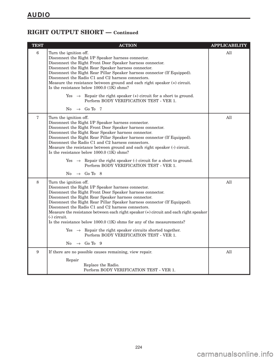
TEST ACTION APPLICABILITY
6 Turn the ignition off.
Disconnect the Right I/P Speaker harness connector.
Disconnect the Right Front Door Speaker harness connector.
Disconnect the Right Rear Speaker harness connector.
Disconnect the Right Rear Pillar Speaker harness connector (If Equipped).
Disconnect the Radio C1 and C2 harness connectors.
Measure the resistance between ground and each right speaker (+) circuit.
Is the resistance below 1000.0 (1K) ohms?All
Ye s®Repair the right speaker (+) circuit for a short to ground.
Perform BODY VERIFICATION TEST - VER 1.
No®Go To 7
7 Turn the ignition off.
Disconnect the Right I/P Speaker harness connector.
Disconnect the Right Front Door Speaker harness connector.
Disconnect the Right Rear Speaker harness connector.
Disconnect the Right Rear Pillar Speaker harness connector (If Equipped).
Disconnect the Radio C1 and C2 harness connectors.
Measure the resistance between ground and each right speaker (-) circuit.
Is the resistance below 1000.0 (1K) ohms?All
Ye s®Repair the right speaker (-) circuit for a short to ground.
Perform BODY VERIFICATION TEST - VER 1.
No®Go To 8
8 Turn the ignition off.
Disconnect the Right I/P Speaker harness connector.
Disconnect the Right Front Door Speaker harness connector.
Disconnect the Right Rear Speaker harness connector.
Disconnect the Right Rear Pillar Speaker harness connector (If Equipped).
Disconnect the Radio C1 and C2 harness connectors.
Measure the resistance between each right speaker (+) circuit and each right speaker
(-) circuit.
Is the resistance below 1000.0 (1K) ohms for any of the measurements?All
Ye s®Repair the right speaker circuits shorted together.
Perform BODY VERIFICATION TEST - VER 1.
No®Go To 9
9 If there are no possible causes remaining, view repair. All
Repair
Replace the Radio.
Perform BODY VERIFICATION TEST - VER 1.
224
AUDIO
RIGHT OUTPUT SHORT ÐContinued
Page 298 of 4284
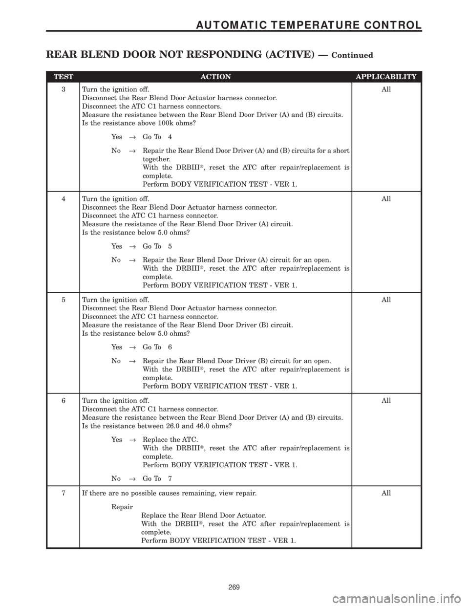
TEST ACTION APPLICABILITY
3 Turn the ignition off.
Disconnect the Rear Blend Door Actuator harness connector.
Disconnect the ATC C1 harness connectors.
Measure the resistance between the Rear Blend Door Driver (A) and (B) circuits.
Is the resistance above 100k ohms?All
Ye s®Go To 4
No®Repair the Rear Blend Door Driver (A) and (B) circuits for a short
together.
With the DRBIIIt, reset the ATC after repair/replacement is
complete.
Perform BODY VERIFICATION TEST - VER 1.
4 Turn the ignition off.
Disconnect the Rear Blend Door Actuator harness connector.
Disconnect the ATC C1 harness connector.
Measure the resistance of the Rear Blend Door Driver (A) circuit.
Is the resistance below 5.0 ohms?All
Ye s®Go To 5
No®Repair the Rear Blend Door Driver (A) circuit for an open.
With the DRBIIIt, reset the ATC after repair/replacement is
complete.
Perform BODY VERIFICATION TEST - VER 1.
5 Turn the ignition off.
Disconnect the Rear Blend Door Actuator harness connector.
Disconnect the ATC C1 harness connector.
Measure the resistance of the Rear Blend Door Driver (B) circuit.
Is the resistance below 5.0 ohms?All
Ye s®Go To 6
No®Repair the Rear Blend Door Driver (B) circuit for an open.
With the DRBIIIt, reset the ATC after repair/replacement is
complete.
Perform BODY VERIFICATION TEST - VER 1.
6 Turn the ignition off.
Disconnect the ATC C1 harness connector.
Measure the resistance between the Rear Blend Door Driver (A) and (B) circuits.
Is the resistance between 26.0 and 46.0 ohms?All
Ye s®Replace the ATC.
With the DRBIIIt, reset the ATC after repair/replacement is
complete.
Perform BODY VERIFICATION TEST - VER 1.
No®Go To 7
7 If there are no possible causes remaining, view repair. All
Repair
Replace the Rear Blend Door Actuator.
With the DRBIIIt, reset the ATC after repair/replacement is
complete.
Perform BODY VERIFICATION TEST - VER 1.
269
AUTOMATIC TEMPERATURE CONTROL
REAR BLEND DOOR NOT RESPONDING (ACTIVE) ÐContinued
Page 304 of 4284
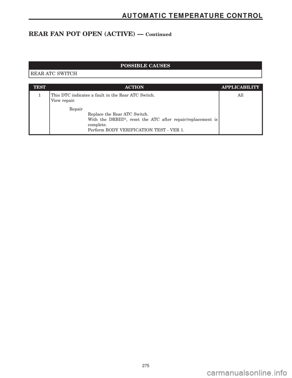
POSSIBLE CAUSES
REAR ATC SWITCH
TEST ACTION APPLICABILITY
1 This DTC indicates a fault in the Rear ATC Switch.
View repair.All
Repair
Replace the Rear ATC Switch.
With the DRBIIIt, reset the ATC after repair/replacement is
complete.
Perform BODY VERIFICATION TEST - VER 1.
275
AUTOMATIC TEMPERATURE CONTROL
REAR FAN POT OPEN (ACTIVE) ÐContinued
Page 306 of 4284

TEST ACTION APPLICABILITY
3 Turn the ignition off.
Disconnect the Rear Automatic Temperature Control Switch harness connector.
Disconnect the ATC C2 harness connector.
Turn the ignition on.
Measure the voltage of the KDB Data circuit.
Is the voltage above 1.0 volt?All
Ye s®Repair the KDB Data circuit for a short to voltage.
With the DRBIIIt, reset the ATC after repair/replacement is
complete.
Perform BODY VERIFICATION TEST - VER 1.
No®Go To 4
4 Turn the ignition off.
Disconnect the Rear Automatic Temperature Control Switch harness connector.
Use Scope input cable CH7058, Cable to Probe adapter CH7062, and the red and
black test probes.
Connect the scope input cable to the channel one connector on the DRB. Attach the
red and black leads and the cable to probe adapter to the scope input cable.
Select Lab Scope.
Select Live.
Select 12 volt square wave.
Press F2 for Scope.
Press F2 and use the arrows to set the voltage range to 20 volts, the Offset to 4.0, and
the Probe to x10. Press F2 again and set the divisions to 40ms/Div, then press F2
again when complete.
Connect the Black lead to the chassis ground. Connect the Red lead to the KDB Clock
circuit in the Rear Automatic Temperature Control Switch harness connector.
Turn the ignition on.
Observe the voltage display on the DRB Lab Scope.
NOTE: The lab scope pattern should look similar to the example given in the
support material and cycle from approximately 0 volts to 8.0 volts.
Did the lab scope pattern and voltage react as noted above?All
Ye s®Go To 5
No®Go To 6
5 If there are no possible causes remaining, view repair. All
Repair
Replace the Rear Automatic Temperature Control Switch.
With the DRBIIIt, reset the ATC after repair/replacement is
complete.
Perform BODY VERIFICATION TEST - VER 1.
6 Turn the ignition off.
Disconnect the Rear Automatic Temperature Control Switch harness connector.
Disconnect the ATC C2 harness connector.
Turn the ignition on.
Measure the voltage of the KDB Clock circuit.
Is the voltage above 1.0 volt?All
Ye s®Repair the KDB Clock circuit for a short to voltage.
With the DRBIIIt, reset the ATC after repair/replacement is
complete.
Perform BODY VERIFICATION TEST - VER 1.
No®Go To 7
277
AUTOMATIC TEMPERATURE CONTROL
REAR IR SENSOR NOT CALIBRATED (ACTIVE) ÐContinued
Page 307 of 4284

TEST ACTION APPLICABILITY
7 Turn the ignition off.
Disconnect the Rear Automatic Temperature Control Switch harness connector.
Disconnect the ATC C2 harness connector.
Measure the resistance between ground and the KDB Clock circuit.
Is the resistance above 100k ohms?All
Ye s®Go To 8
No®Repair the KDB Clock circuit for a short to ground.
With the DRBIIIt, reset the ATC after repair/replacement is
complete.
Perform BODY VERIFICATION TEST - VER 1.
8 Turn the ignition off.
Disconnect the Rear Automatic Temperature Control Switch harness connector.
Disconnect the ATC C2 harness connector.
Measure the resistance of the KDB Clock circuit.
Is the resistance below 5.0 ohms?All
Ye s®Go To 9
No®Repair the KDB Clock circuit for an open.
With the DRBIIIt, reset the ATC after repair/replacement is
complete.
Perform BODY VERIFICATION TEST - VER 1.
9 If there are no possible causes remaining, view repair. All
Repair
Replace the ATC.
With the DRBIIIt, reset the ATC after repair/replacement is
complete.
Perform BODY VERIFICATION TEST - VER 1.
10 Turn the ignition off.
Disconnect the Rear Automatic Temperature Control Switch harness connector.
Disconnect the ATC C2 harness connector.
Measure the resistance between ground and the KDB Data circuit.
Is the resistance above 100k ohms?All
Ye s®Go To 11
No®Repair the KDB Data circuit for a short to ground.
With the DRBIIIt, reset the ATC after repair/replacement is
complete.
Perform BODY VERIFICATION TEST - VER 1.
11 Turn the ignition off.
Disconnect the Rear Automatic Temperature Control Switch harness connector.
Disconnect the ATC C2 harness connector.
Measure the resistance of the KDB Data circuit.
Is the resistance below 5.0 ohms?All
Ye s®Go To 12
No®Repair the KDB Data circuit for an open.
With the DRBIIIt, reset the ATC after repair/replacement is
complete.
Perform BODY VERIFICATION TEST - VER 1.
278
AUTOMATIC TEMPERATURE CONTROL
REAR IR SENSOR NOT CALIBRATED (ACTIVE) ÐContinued