CHRYSLER VOYAGER 2002 Service Manual
Manufacturer: CHRYSLER, Model Year: 2002, Model line: VOYAGER, Model: CHRYSLER VOYAGER 2002Pages: 2399, PDF Size: 57.96 MB
Page 121 of 2399
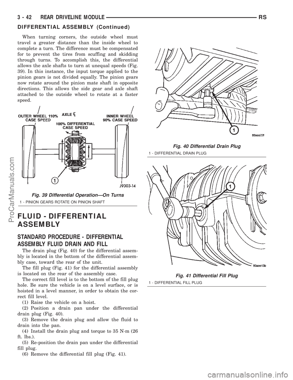
When turning corners, the outside wheel must
travel a greater distance than the inside wheel to
complete a turn. The difference must be compensated
for to prevent the tires from scuffing and skidding
through turns. To accomplish this, the differential
allows the axle shafts to turn at unequal speeds (Fig.
39). In this instance, the input torque applied to the
pinion gears is not divided equally. The pinion gears
now rotate around the pinion mate shaft in opposite
directions. This allows the side gear and axle shaft
attached to the outside wheel to rotate at a faster
speed.
FLUID - DIFFERENTIAL
ASSEMBLY
STANDARD PROCEDURE - DIFFERENTIAL
ASSEMBLY FLUID DRAIN AND FILL
The drain plug (Fig. 40) for the differential assem-
bly is located in the bottom of the differential assem-
bly case, toward the rear of the unit.
The fill plug (Fig. 41) for the differential assembly
is located on the rear of the assembly case.
The correct fill level is to the bottom of the fill plug
hole. Be sure the vehicle is on a level surface, or is
hoisted in a level manner, in order to obtain the cor-
rect fill level.
(1) Raise the vehicle on a hoist.
(2) Position a drain pan under the differential
drain plug (Fig. 40).
(3) Remove the drain plug and allow the fluid to
drain into the pan.
(4) Install the drain plug and torque to 35 N´m (26
ft. lbs.).
(5) Re-position the drain pan under the differential
fill plug.
(6) Remove the differential fill plug (Fig. 41).
Fig. 39 Differential OperationÐOn Turns
1 - PINION GEARS ROTATE ON PINION SHAFT
Fig. 40 Differential Drain Plug
1 - DIFFERENTIAL DRAIN PLUG
Fig. 41 Differential Fill Plug
1 - DIFFERENTIAL FILL PLUG
3 - 42 REAR DRIVELINE MODULERS
DIFFERENTIAL ASSEMBLY (Continued)
ProCarManuals.com
Page 122 of 2399
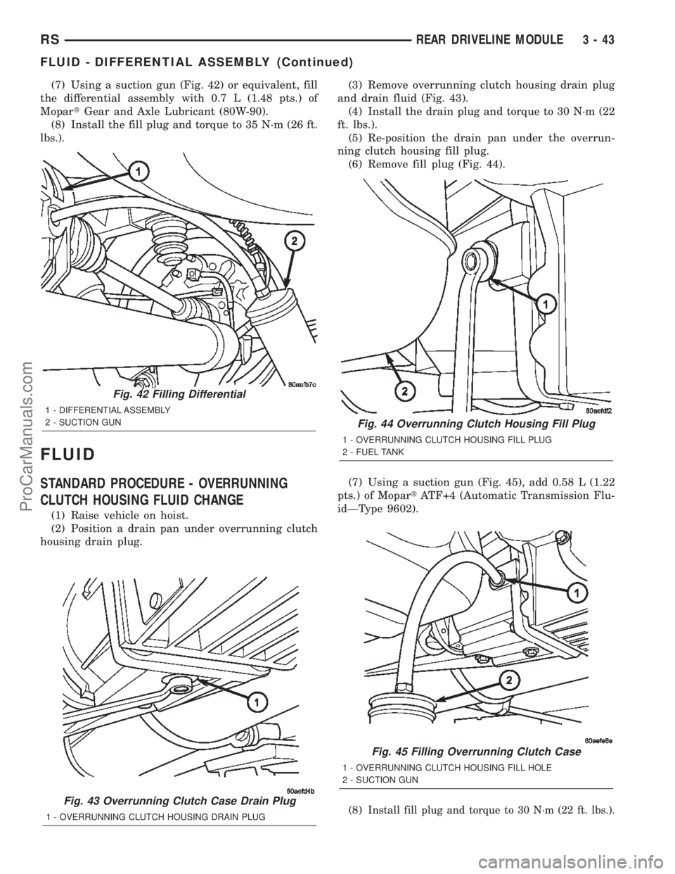
(7) Using a suction gun (Fig. 42) or equivalent, fill
the differential assembly with 0.7 L (1.48 pts.) of
MopartGear and Axle Lubricant (80W-90).
(8) Install the fill plug and torque to 35 N´m (26 ft.
lbs.).
FLUID
STANDARD PROCEDURE - OVERRUNNING
CLUTCH HOUSING FLUID CHANGE
(1) Raise vehicle on hoist.
(2) Position a drain pan under overrunning clutch
housing drain plug.(3) Remove overrunning clutch housing drain plug
and drain fluid (Fig. 43).
(4) Install the drain plug and torque to 30 N´m (22
ft. lbs.).
(5) Re-position the drain pan under the overrun-
ning clutch housing fill plug.
(6) Remove fill plug (Fig. 44).
(7) Using a suction gun (Fig. 45), add 0.58 L (1.22
pts.) of MopartATF+4 (Automatic Transmission Flu-
idÐType 9602).
(8)
Install fill plug and torque to 30 N´m (22 ft. lbs.).Fig. 43 Overrunning Clutch Case Drain Plug
1 - OVERRUNNING CLUTCH HOUSING DRAIN PLUG
Fig. 42 Filling Differential
1 - DIFFERENTIAL ASSEMBLY
2 - SUCTION GUN
Fig. 44 Overrunning Clutch Housing Fill Plug
1 - OVERRUNNING CLUTCH HOUSING FILL PLUG
2 - FUEL TANK
Fig. 45 Filling Overrunning Clutch Case
1 - OVERRUNNING CLUTCH HOUSING FILL HOLE
2 - SUCTION GUN
RSREAR DRIVELINE MODULE3-43
FLUID - DIFFERENTIAL ASSEMBLY (Continued)
ProCarManuals.com
Page 123 of 2399
VISCOUS COUPLER
DESCRIPTION
The heart of the all-wheel drive system is the
inter-axle viscous coupling and bi-directional over-
running clutch. Under normal driving the vehicle
retains predominantly front wheel drive characteris-
tics. The all-wheel drive takes effect when the front
wheels start to slip. Under normal level road,
straight line driving, 100% of the torque is allocated
to the front wheels. The viscous coupler allows more
torque to the rear wheels in accordance with the
amount of slippage at the front wheels. The variable
torque distribution is automatic with no driver
inputs required.
OPERATION
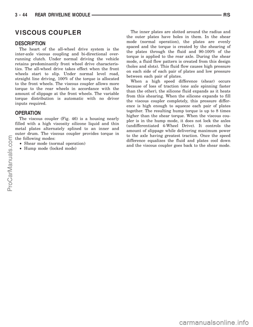
The viscous coupler (Fig. 46) is a housing nearly
filled with a high viscosity silicone liquid and thin
metal plates alternately splined to an inner and
outer drum. The viscous coupler provides torque in
the following modes:
²Shear mode (normal operation)
²Hump mode (locked mode)The inner plates are slotted around the radius and
the outer plates have holes in them. In the shear
mode (normal operation), the plates are evenly
spaced and the torque is created by the shearing of
the plates through the fluid and 90-100% of the
torque is applied to the rear axle. During the shear
mode, a fluid flow pattern is created from this design
(holes and slots). This fluid flow causes high pressure
on each side of each pair of plates and low pressure
between each pair of plates.
When a high speed difference (shear) occurs
because of loss of traction (one axle spinning faster
than the other), the silicone fluid expands as it heats
from this shearing. When the silicone expands to fill
the viscous coupler completely, this pressure differ-
ence is high enough to squeeze each pair of plates
together. The resulting hump torque is up to 8 times
higher than the shear torque. When the viscous cou-
pler is in the hump mode, it does not lock the axles
(undifferentiated 4-Wheel Drive). It controls the
amount of slippage while delivering maximum power
to the axle having greatest traction. Once the speed
difference equalizes the fluid and plates cool down
and the viscous coupler goes back to the shear mode.
3 - 44 REAR DRIVELINE MODULERS
ProCarManuals.com
Page 124 of 2399
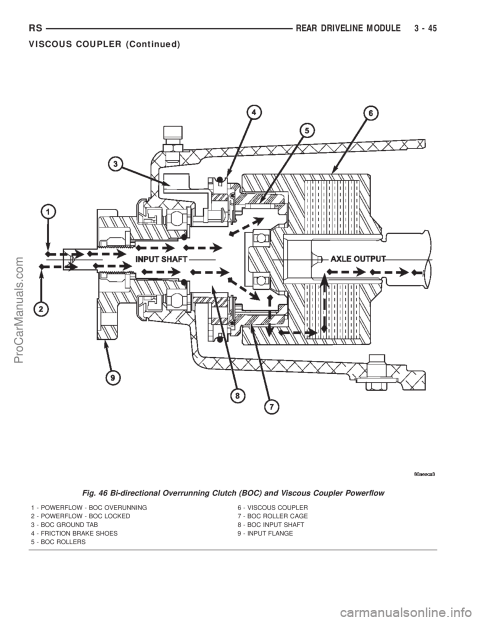
Fig. 46 Bi-directional Overrunning Clutch (BOC) and Viscous Coupler Powerflow
1 - POWERFLOW - BOC OVERUNNING 6 - VISCOUS COUPLER
2 - POWERFLOW - BOC LOCKED 7 - BOC ROLLER CAGE
3 - BOC GROUND TAB 8 - BOC INPUT SHAFT
4 - FRICTION BRAKE SHOES 9 - INPUT FLANGE
5 - BOC ROLLERS
RSREAR DRIVELINE MODULE3-45
VISCOUS COUPLER (Continued)
ProCarManuals.com
Page 125 of 2399
TORQUE ARM
REMOVAL
(1) Raise vehicle on hoist.
(2) Remove rear driveline module assembly. (Refer
to 3 - DIFFERENTIAL & DRIVELINE/REAR DRIV-
ELINE MODULE - REMOVAL)
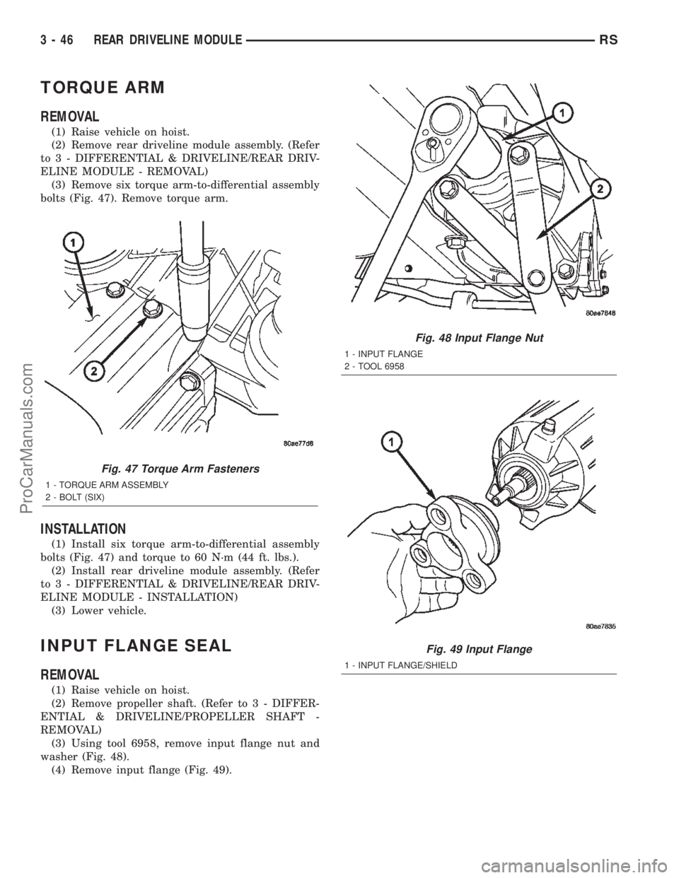
(3) Remove six torque arm-to-differential assembly
bolts (Fig. 47). Remove torque arm.
INSTALLATION
(1) Install six torque arm-to-differential assembly
bolts (Fig. 47) and torque to 60 N´m (44 ft. lbs.).
(2) Install rear driveline module assembly. (Refer
to 3 - DIFFERENTIAL & DRIVELINE/REAR DRIV-
ELINE MODULE - INSTALLATION)
(3) Lower vehicle.
INPUT FLANGE SEAL
REMOVAL
(1) Raise vehicle on hoist.
(2) Remove propeller shaft. (Refer to 3 - DIFFER-
ENTIAL & DRIVELINE/PROPELLER SHAFT -
REMOVAL)
(3) Using tool 6958, remove input flange nut and
washer (Fig. 48).
(4) Remove input flange (Fig. 49).
Fig. 47 Torque Arm Fasteners
1 - TORQUE ARM ASSEMBLY
2 - BOLT (SIX)
Fig. 48 Input Flange Nut
1 - INPUT FLANGE
2 - TOOL 6958
Fig. 49 Input Flange
1 - INPUT FLANGE/SHIELD
3 - 46 REAR DRIVELINE MODULERS
ProCarManuals.com
Page 126 of 2399
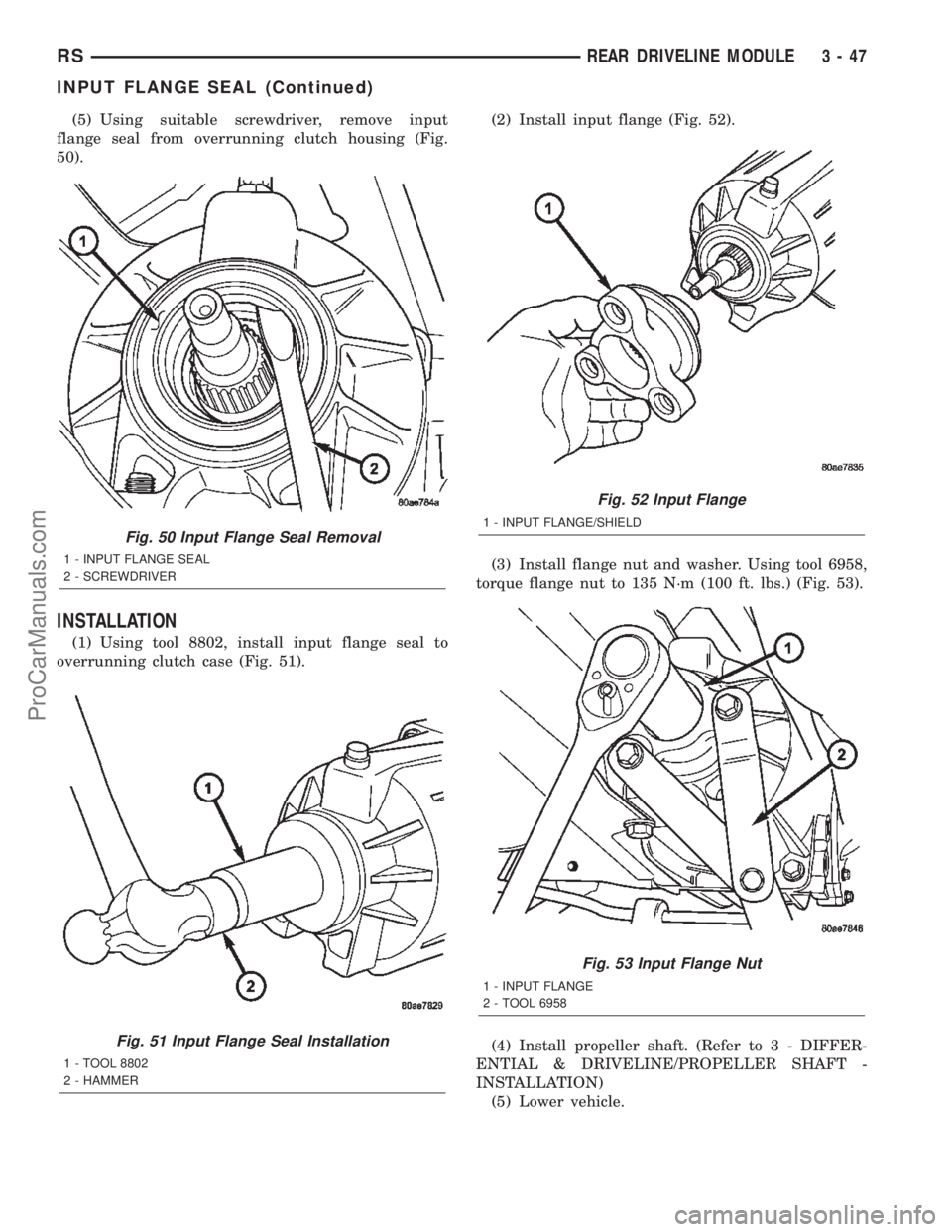
(5) Using suitable screwdriver, remove input
flange seal from overrunning clutch housing (Fig.
50).
INSTALLATION
(1) Using tool 8802, install input flange seal to
overrunning clutch case (Fig. 51).(2) Install input flange (Fig. 52).
(3) Install flange nut and washer. Using tool 6958,
torque flange nut to 135 N´m (100 ft. lbs.) (Fig. 53).
(4) Install propeller shaft. (Refer to 3 - DIFFER-
ENTIAL & DRIVELINE/PROPELLER SHAFT -
INSTALLATION)
(5) Lower vehicle.
Fig. 50 Input Flange Seal Removal
1 - INPUT FLANGE SEAL
2 - SCREWDRIVER
Fig. 51 Input Flange Seal Installation
1 - TOOL 8802
2 - HAMMER
Fig. 52 Input Flange
1 - INPUT FLANGE/SHIELD
Fig. 53 Input Flange Nut
1 - INPUT FLANGE
2 - TOOL 6958
RSREAR DRIVELINE MODULE3-47
INPUT FLANGE SEAL (Continued)
ProCarManuals.com
Page 127 of 2399
OUTPUT FLANGE SEAL
REMOVAL
(1) Raise vehicle on hoist.
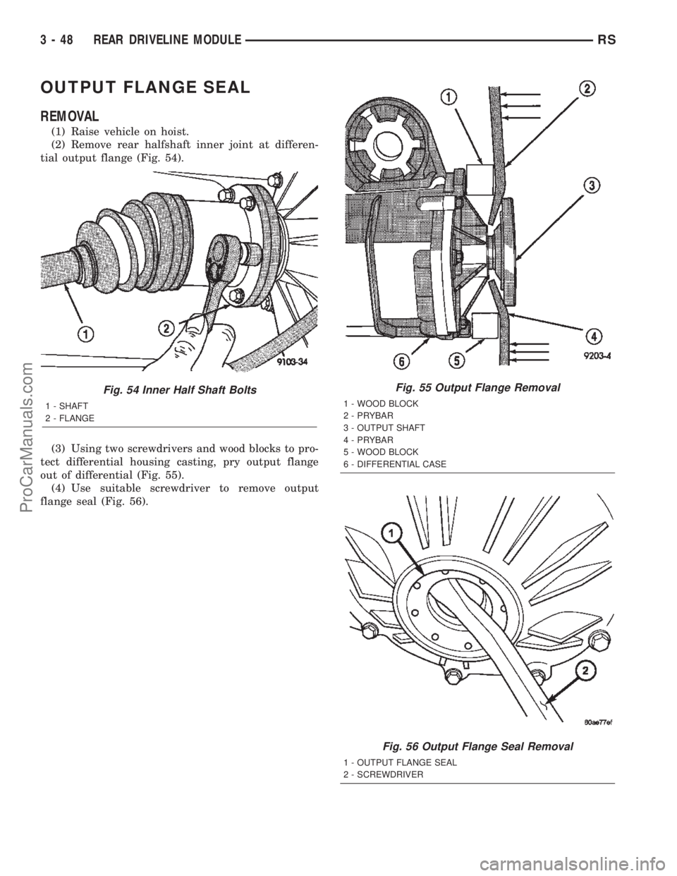
(2) Remove rear halfshaft inner joint at differen-
tial output flange (Fig. 54).
(3) Using two screwdrivers and wood blocks to pro-
tect differential housing casting, pry output flange
out of differential (Fig. 55).
(4) Use suitable screwdriver to remove output
flange seal (Fig. 56).
Fig. 54 Inner Half Shaft Bolts
1 - SHAFT
2 - FLANGE
Fig. 55 Output Flange Removal
1 - WOOD BLOCK
2 - PRYBAR
3 - OUTPUT SHAFT
4 - PRYBAR
5 - WOOD BLOCK
6 - DIFFERENTIAL CASE
Fig. 56 Output Flange Seal Removal
1 - OUTPUT FLANGE SEAL
2 - SCREWDRIVER
3 - 48 REAR DRIVELINE MODULERS
ProCarManuals.com
Page 128 of 2399
INSTALLATION
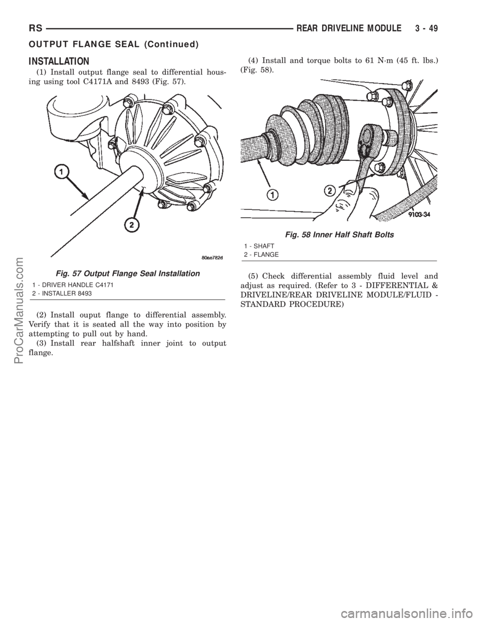
(1) Install output flange seal to differential hous-
ing using tool C4171A and 8493 (Fig. 57).
(2) Install ouput flange to differential assembly.
Verify that it is seated all the way into position by
attempting to pull out by hand.
(3) Install rear halfshaft inner joint to output
flange.(4) Install and torque bolts to 61 N´m (45 ft. lbs.)
(Fig. 58).
(5) Check differential assembly fluid level and
adjust as required. (Refer to 3 - DIFFERENTIAL &
DRIVELINE/REAR DRIVELINE MODULE/FLUID -
STANDARD PROCEDURE)
Fig. 57 Output Flange Seal Installation
1 - DRIVER HANDLE C4171
2 - INSTALLER 8493
Fig. 58 Inner Half Shaft Bolts
1 - SHAFT
2 - FLANGE
RSREAR DRIVELINE MODULE3-49
OUTPUT FLANGE SEAL (Continued)
ProCarManuals.com
Page 129 of 2399

ProCarManuals.com
Page 130 of 2399
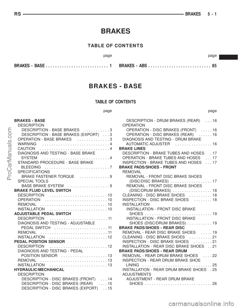
BRAKES
TABLE OF CONTENTS
page page
BRAKES - BASE........................... 1BRAKES - ABS........................... 85
BRAKES - BASE
TABLE OF CONTENTS
page page
BRAKES - BASE
DESCRIPTION
DESCRIPTION - BASE BRAKES...........3
DESCRIPTION - BASE BRAKES (EXPORT) . . . 3
OPERATION - BASE BRAKES..............3
WARNING.............................4
CAUTION..............................4
DIAGNOSIS AND TESTING - BASE BRAKE
SYSTEM.............................4
STANDARD PROCEDURE - BASE BRAKE
BLEEDING............................7
SPECIFICATIONS
BRAKE FASTENER TORQUE.............9
SPECIAL TOOLS
BASE BRAKE SYSTEM..................9
BRAKE FLUID LEVEL SWITCH
DESCRIPTION.........................10
OPERATION...........................10
REMOVAL.............................10
INSTALLATION.........................10
ADJUSTABLE PEDAL SWITCH
DESCRIPTION.........................11
DIAGNOSIS AND TESTING - ADJUSTABLE
PEDAL SWITCH.......................11
REMOVAL.............................11
INSTALLATION.........................12
PEDAL POSITION SENSOR
DESCRIPTION.........................12
DIAGNOSIS AND TESTING - PEDAL
POSITION SENSOR....................13
REMOVAL.............................13
INSTALLATION.........................13
HYDRAULIC/MECHANICAL
DESCRIPTION
DESCRIPTION - DISC BRAKES (FRONT) . . . 14
DESCRIPTION - DISC BRAKES (REAR)....15
DESCRIPTION - DISC BRAKES (EXPORT) . . 15DESCRIPTION - DRUM BRAKES (REAR) . . . 16
OPERATION
OPERATION - DISC BRAKES (FRONT).....16
OPERATION - DISC BRAKES (REAR)......16
DIAGNOSIS AND TESTING - DRUM BRAKE
AUTOMATIC ADJUSTER................16
BRAKE LINES
DESCRIPTION - BRAKE TUBES AND HOSES . 17
OPERATION - BRAKE TUBES AND HOSES . . . 17
INSPECTION - BRAKE TUBES AND HOSES . . . 17
BRAKE PADS/SHOES - FRONT
REMOVAL
REMOVAL - FRONT DISC BRAKE SHOES
(DISC/DISC BRAKES)..................17
REMOVAL - FRONT DISC BRAKE SHOES
(DISC/DRUM BRAKES).................18
CLEANING - DISC BRAKE SHOES..........18
INSPECTION - DISC BRAKE SHOES........18
INSTALLATION
INSTALLATION - FRONT DISC BRAKE
SHOES.............................19
INSTALLATION - FRONT DISC BRAKE
SHOES (DISC/DRUM BRAKES)...........19
BRAKE PADS/SHOES - REAR DISC
REMOVAL - REAR DISC BRAKE SHOES.....19
CLEANING - DISC BRAKE SHOES..........21
INSPECTION - DISC BRAKE SHOES........21
INSTALLATION - REAR DISC BRAKE SHOES . . 21
BRAKE PADS/SHOES - REAR DRUM
REMOVAL - REAR DRUM BRAKE SHOES....22
INSPECTION - REAR DRUM BRAKE SHOE
LINING..............................25
INSTALLATION - REAR DRUM BRAKE SHOES . 25
ADJUSTMENTS
ADJUSTMENT - REAR DRUM BRAKE
SHOES.............................26
RSBRAKES5-1
ProCarManuals.com