Citroen C4 2016 2.G Owner's Manual
Manufacturer: CITROEN, Model Year: 2016, Model line: C4, Model: Citroen C4 2016 2.GPages: 396, PDF Size: 10.22 MB
Page 241 of 396
239
C4-2_en_Chap08_en-cas-de-panne_ed02-2015
Temporary puncture r epair k it
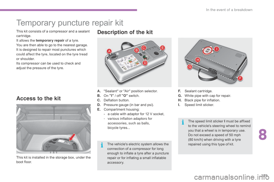
Access to the kit
This kit is installed i n t he s torage b ox, u nder t he b
oot floor. A.
"
Sealant" or "Air" position selector.
B.
On
"I"
/ off "O"
s
witch.
C.
D
eflation button.
D.
P
ressure gauge (in bar and psi).
E.
C
ompartment
h
ousing:
-
a
cable with adaptor for 12 V socket,
-
v
arious inflation adaptors for
accessories, such as balls,
bicycle tyres...
Description of the kit
F. Sealant c artridge.
G. W hite pipe with cap for repair.
H.
B
lack pipe for inflation.
I.
S
peed limit sticker.
This
kit
consists
of
a
compressor
and
a
sealant
c
artridge.
It allows the temporary repair
of
a
tyre.
You
are
then
able
to
go
to
the
nearest
garage.
It
is
designed
to
repair
most
punctures
which
c
ould affect the tyre, located on the tyre tread
or
shoulder.
Its
compressor
can
be
used
to
check
and
a
djust
the
pressure
of
the
tyre.
The
vehicle's
electric
system
allows
the
c
onnection
of
a
compressor
for
long
e
nough
to
inflate
a
tyre
after
a
puncture
r
epair
or
for
inflating
a
small
inflatable
a
ccessory. The
speed limit sticker I must be affixed
t
o the vehicle's steering wheel to remind
y
ou that a wheel is in temporary use.
Do
not exceed a speed of 50 mph
(80
km/h) when driving with a tyre
r
epaired using this type of kit.
8
In the event of a breakdown
Page 242 of 396
240
C4-2_en_Chap08_en-cas-de-panne_ed02-2015
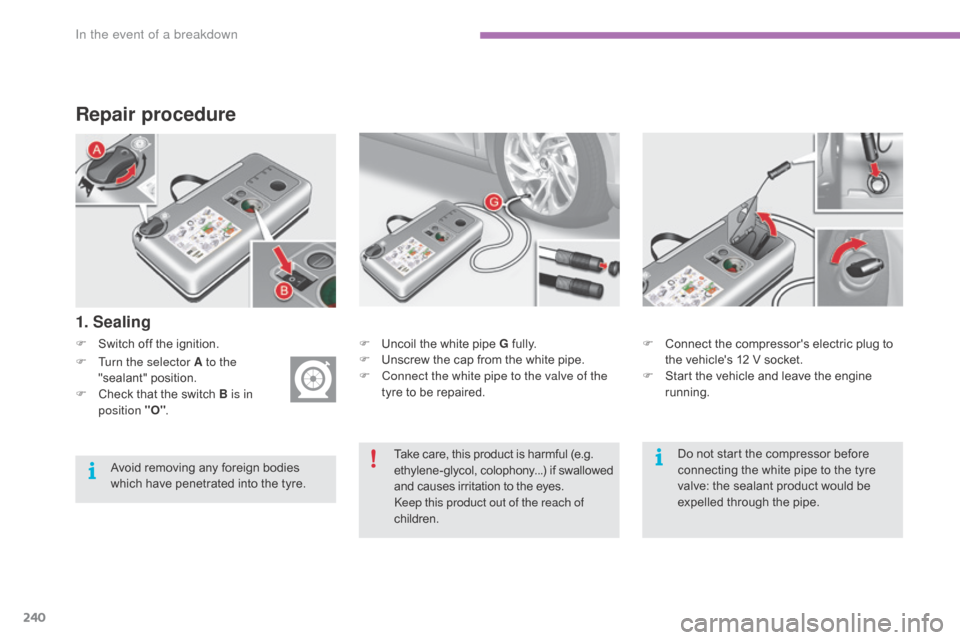
Repair procedure
F Switch off the ignition.
1. Sealing
F Uncoil the white pipe G f ully.
F U nscrew the cap from the white pipe.
F
C
onnect the white pipe to the valve of the
tyre
to be repaired. F
C onnect the compressor's electric plug to t
he vehicle's 12 V socket.
F
S
tart the vehicle and leave the engine
r
unning.
F
T
urn the selector A to the
"sealant"
p
osition.
F
C
heck
that
the
switch
B is in
position "O" .
Take
care, this product is harmful (e.g.
e
thylene-glycol, colophony...) if swallowed
a
nd causes irritation to the eyes.
Keep this product out of the reach of
children.
Avoid
removing
any
foreign
bodies
w
hich
have
penetrated
into
the
tyre. Do
not start the compressor before
c
onnecting the white pipe to the tyre
v
alve: the sealant product would be
e
xpelled through the pipe.
In the event of a breakdown
Page 243 of 396
241
C4-2_en_Chap08_en-cas-de-panne_ed02-2015
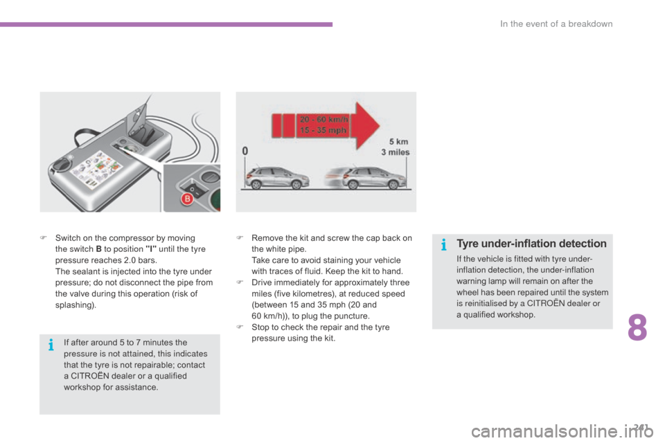
F Switch on the compressor by moving t
he switch B to position "I" until the tyre
pressure
reaches 2.0 bars.
T
he sealant is injected into the tyre under
p
ressure; do not disconnect the pipe from
t
he valve during this operation (risk of
sp
lashing). F
R emove the kit and screw the cap back on t
he white pipe.
T
ake care to avoid staining your vehicle
w
ith traces of fluid. Keep the kit to hand.
F
D
rive immediately for approximately three
m
iles (five kilometres), at reduced speed
(
between 15 and 35 mph (20 and
60
km/h)), to plug the puncture.
F
S
top to check the repair and the tyre
p
ressure using the kit.
If
after around 5 to 7 minutes the
p
ressure is not attained, this indicates
that
the tyre is not repairable; contact
a
CITROËN dealer or a qualified
w
orkshop for assistance.Tyre under-inflation detection
If the vehicle is fitted with tyre under-
inflation detection, the under-inflation
warning lamp will remain on after the
w
heel has been repaired until the system
i
s reinitialised by a CITROËN dealer or
a qualified
workshop.
8
In the event of a breakdown
Page 244 of 396
242
C4-2_en_Chap08_en-cas-de-panne_ed02-2015
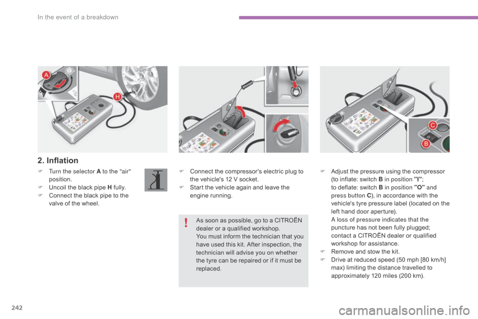
F Connect the compressor's electric plug to t
he vehicle's 12 V socket.
F
S
tart the vehicle again and leave the
e
ngine
r
unning.
F
T
urn the selector A to the "air"
position.
F
U
ncoil
the
black
pipe
H
f
ully.
F
C
onnect
the
black
pipe
to
the
v
alve
of
the
wheel.
2. Inflation
F Adjust the pressure using the compressor (
to inflate: switch B in position "I";
t
o deflate: switch B in position "O" and
press button C ),
in accordance with the
v
ehicle's
t
yre pressure label (located on the
l
eft hand door aperture).
A l
oss of pressure indicates that the
puncture
has not been fully plugged;
c
ontact a CITROËN dealer or qualified
w
orkshop for assistance.
F
R
emove and stow the kit.
F
D
rive at reduced speed (50 mph [80 km/h]
m
ax) limiting the distance travelled to
a
pproximately 120 miles (200 km).
As
soon
as
possible,
go
to
a
CITROËN
d
ealer
or
a
qualified
workshop.
You
must
inform
the
technician
that
you
h
ave
used
this
kit.
After
inspection,
the
t
echnician will advise you on whether
the
tyre
can
be
repaired
or
if
it
must
be
r
eplaced.
In the event of a breakdown
Page 245 of 396
243
C4-2_en_Chap08_en-cas-de-panne_ed02-2015
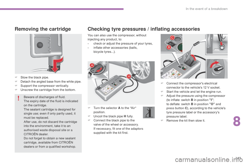
Removing the cartridge
F Stow the black pipe.
F D etach the angled base from the white pipe.
F
S
upport the compressor vertically.
F
U
nscrew the cartridge from the bottom. F
C
onnect the compressor's electrical
c
onnector to the vehicle's 12 V socket.
F
S
tart the vehicle and let the engine run.
F
A
djust the pressure using the compressor
(
to inflate: switch B in position "I";
t
o deflate: switch B in position "O" and
press button C ),
according to the vehicle's
t
yre pressure label or the accessory's
p
ressure label.
F
R
emove the kit then stow it.
Checking tyre pressures / inflating accessories
You can also use the compressor, without injecting any product, to:
-
c
heck or adjust the pressure of your tyres,
-
i
nflate other accessories (balls,
b
icycle tyres...).
F
T
urn the selector A to the "Air"
position.
F
U
ncoil the black pipe H
f
ully.
F
C
onnect the black pipe to the
v
alve of the wheel or accessory.
I
f necessary, fit one of the adaptors
supplied
with the kit first.
Beware
of
discharges
of
fluid.
The
expiry
date
of
the
fluid
is
indicated
o
n
the
cartridge.
The
sealant
cartridge
is
designed
for
s
ingle
use;
even
if
only
partly
used,
it
m
ust
be
replaced.
After
use,
do
not
discard
the
cartridge
i
nto
the
environment,
take
it
to
an
a
uthorised waste disposal site or a
CITROËN
dealer.
Do
not
forget
to
obtain
a
new
sealant
c
artridge,
available
from
CITROËN
d
ealers
or
from
a
qualified
workshop.
8
In the event of a breakdown
Page 246 of 396
244
C4-2_en_Chap08_en-cas-de-panne_ed02-2015
Spare wheel
Access to the tools
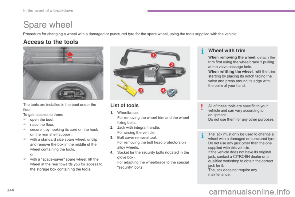
The tools are installed in the boot under the
f l o o r.
To gain access to them:
F
o
pen the boot,
F
r
aise the floor,
F
s
ecure it by hooking its cord on the hook
o
n the rear shelf support,
F
w
ith a standard size spare wheel, unclip
and
remove the box in the middle of the
w
heel containing the tools,
or
F
w
ith a "space-saver" spare wheel; lift the
w
heel at the rear towards you for access to
the
storage box containing the tools.List of tools Wheel with trim
When removing the wheel
, detach the
trim first using the wheelbrace 1 pulling
a
t the valve passage hole.
When refitting the wheel ,
refit the trim
s
tarting by placing its notch facing the
v
alve and press around its edge with
t
he palm of your hand.
Procedure
for
changing
a
wheel
with
a
damaged
or
punctured
tyre
for
the
spare
wheel,
using
the
tools
supplied with the vehicle.
All of these tools are specific to your
vehicle and can vary according to
e
quipment.
Do
not use them for any other purposes.
1.
W
heelbrace.
F
or
removing
the
wheel
trim
and
the
wheel
f
ixing
bol
ts.
2.
J
ack
with
integral
handle.
F
or
raising
the
vehicle.
3.
B
olt
cover
removal
tool.
F
or
removing
the
bolt
head
protectors
on
a
lloy
wheels.
4.
S
ocket
for
the
security
bolts
(located
in
the
g
love
box).
F
or
adapting
the
wheelbrace
to
the
special
"s
ecurity"
b
olts. The
jack must only be used to change a
w
heel with a damaged or punctured tyre.
Do
not use any jack other than the one
s
upplied with this vehicle.
If
the vehicle does not have its original
j
ack, contact a CITROËN dealer or a
q
ualified workshop to obtain the correct
j
ack for it.
The
jack does not require any
m
aintenance.
In the event of a breakdown
Page 247 of 396
245
C4-2_en_Chap08_en-cas-de-panne_ed02-2015
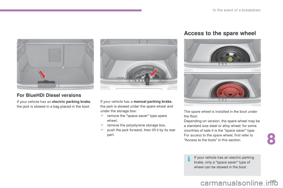
For BlueHDi Diesel versions
If your vehicle has an electric parking brake,
the jack is stowed in a bag placed in the boot.If your vehicle has a manual parking brake
,
the jack is stowed under the spare wheel and
u
nder the storage box:
F
r
emove the "space-saver" type spare
w
heel,
F
r
emove the polystyrene storage box,
F
p
ush the jack for ward, then lift it by its rear
par
t.The spare wheel is installed in the boot under
the
floor.
Depending
on version, the spare wheel may be
a
standard size steel or alloy wheel; for some
c
ountries of sale it is the "space saver" type.
For access to the spare wheel, first refer to
"Access
to the tools" in this section.
Access to the spare wheel
If your vehicle has an electric parking brake, only a "space saver" type of
w
heel can be stowed in the boot.
8
In the event of a breakdown
Page 248 of 396

246
C4-2_en_Chap08_en-cas-de-panne_ed02-2015
Taking out the standard wheel
F Unscrew the yellow central bolt.
F R aise the spare wheel towards you from
t
he rear.
F
T
ake the wheel out of the boot.
Putting the standard wheel back
in place
F Put the wheel back in its housing.
F U nscrew the yellow central bolt by a few
t
urns then put it in place in the centre of the
wheel.
Tyre under-inflation detection
The spare wheel is not fitted with a
sensor. The punctured wheel must be
r
epaired by a CITROËN dealer or a
qualified
w
orkshop.
F
T
ighten fully until the central bolt clicks to
r
etain the wheel correctly.
F
P
ut the box back in place in the centre of
t
he wheel and clip it.
In the event of a breakdown
Page 249 of 396
247
C4-2_en_Chap08_en-cas-de-panne_ed02-2015
Removing a wheel
* position P for an automatic gearbox.
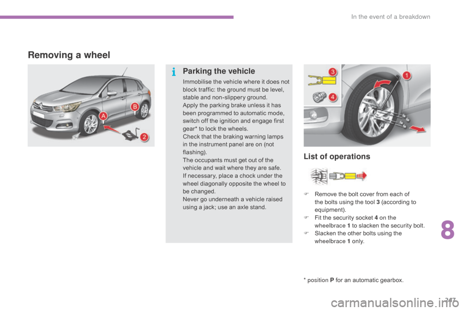
List of operations
Parking the vehicle
Immobilise the vehicle where it does not b
lock traffic: the ground must be level,
s
table and non-slippery ground.
Apply
the parking brake unless it has
b
een programmed to automatic mode,
s
witch off the ignition and engage first
g
ear* to lock the wheels.
Check
that the braking warning lamps
i
n the instrument panel are on (not
f
lashing).
The
occupants must get out of the
v
ehicle and wait where they are safe.
If
necessary, place a chock under the
w
heel diagonally opposite the wheel to
be c
hanged.
Never
go underneath a vehicle raised
u
sing a jack; use an axle stand.F
R
emove the bolt cover from each of
t
he bolts using the tool 3 (according to
e
quipment).
F
F
it the security socket 4 on the
wheelbrace
1 to slacken the security bolt.
F
S
lacken the other bolts using the
w
heelbrace 1
o
n l y.
8
In the event of a breakdown
Page 250 of 396
248
C4-2_en_Chap08_en-cas-de-panne_ed02-2015
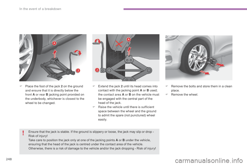
F Place the foot of the jack 2 on the ground a
nd ensure that it is directly below the
front
A or rear B jacking point provided on
t
he underbody, whichever is closest to the
wheel
to be changed.
Ensure
that the jack is stable. If the ground is slippery or loose, the jack may slip or drop -
R
isk of injury!
Take
care to position the jack only at one of the jacking points A or B under the vehicle,
ensuring
that the head of the jack is centred under the contact area of the vehicle.
O
ther wise, there is a risk of damage to the vehicle and/or the jack dropping - Risk of injury!F
R emove the bolts and store them in a clean p
lace.
F
R
emove the wheel.
F
E xtend the jack 2 until its head comes into c
ontact with the jacking point A or B used;
t
he contact area A or B on the vehicle must
b
e engaged with the central part of the
h
ead of the jack.
F
Ra
ise the vehicle until there is sufficient
space
between the wheel and the ground
t
o admit the spare (not punctured) wheel
e
asily.
In the event of a breakdown