Citroen C4 2016 2.G Owner's Manual
Manufacturer: CITROEN, Model Year: 2016, Model line: C4, Model: Citroen C4 2016 2.GPages: 396, PDF Size: 10.22 MB
Page 221 of 396
219
C4-2_en_Chap07_infos-pratiques_ed02-2015
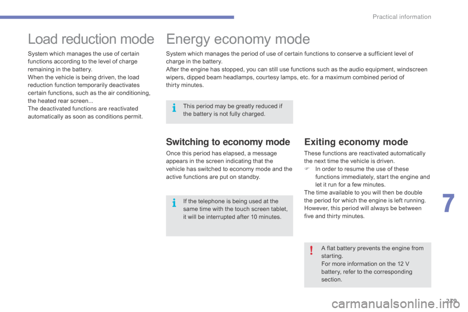
Load reduction modeE nergy ec onomy m ode
Switching to economy mode
Once this period has elapsed, a message a
ppears in the screen indicating that the
v
ehicle has switched to economy mode and the
a
ctive functions are put on standby.
Exiting economy mode
These functions are reactivated automatically the next time the vehicle is driven.
F
I
n order to resume the use of these
f
unctions immediately, start the engine and
l
et it run for a few minutes.
The
time available to you will then be double
t
he period for which the engine is left running.
H
owever, this period will always be between
five
and thirty minutes.
System
which
manages
the
use
of
certain
f
unctions
according
to
the
level
of
charge
r
emaining
in
the
battery.
When
the
vehicle
is
being
driven,
the
load
r
eduction
function
temporarily
deactivates
c
ertain
functions,
such
as
the
air
conditioning,
t
he
heated
rear
screen...
The deactivated functions are reactivated
automatically
as
soon
as
conditions
permit. System
which
manages
the
period
of
use
of
certain
functions to conserve a sufficient level of
c
harge
in
the
battery.
After
the
engine
has
stopped,
you
can
still
use
functions such as the audio equipment, windscreen
w
ipers,
dipped
beam
headlamps, courtesy
lamps,
etc. for a maximum combined period of
t
hirty minutes.
A flat battery prevents the engine from
s
tarting.
For
more information on the 12 V
b
attery, refer to the corresponding
s
ection.
This
period
may
be
greatly
reduced
if
t
he
battery
is
not
fully
charged.
If
the
telephone
is
being
used
at
the
s
ame
time
with
the
touch
screen
tablet,
i
t
will
be
interrupted
after
10
minutes.
7
Practical information
Page 222 of 396
220
C4-2_en_Chap07_infos-pratiques_ed02-2015
Audio pre-equipment
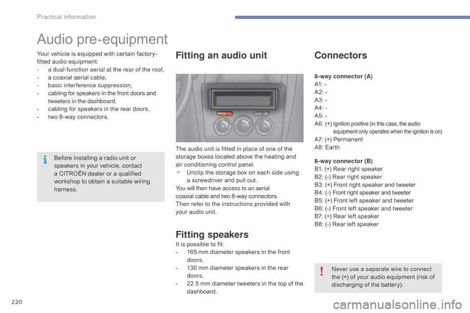
Fitting an audio unit
The audio unit is fitted in place of one of the
storage boxes located above the heating and
a
ir conditioning control panel.
F
U
nclip the storage box on each side using
a
screwdriver and pull out.
You will then have access to an aerial
coaxial
cable and two 8 -way connectors.
Then refer to the instructions provided with
your
audio unit.
Fitting speakers
It is possible to fit:
- 1 65 mm diameter speakers in the front
d
oors,
-
1
30 mm diameter speakers in the rear
d
oors,
-
2
2.5 mm diameter tweeters in the top of the
das
hboard.
Connectors
8-way connector (A)
A1: -
A2:
-
A3:
-
A4:
-
A5:
-
A6:
(+)
Ignition positive (in this case, the audio equipment only operates when the ignition is on)
A7: (+) Permanent
A 8: Earth
8-way connector (B)
B1:
(+) Rear right speaker
B2:
(-) Rear right speaker
B3:
(
+)
F
ront right speaker and tweeter
B 4:
(
-)
F
ront right speaker and tweeter
B5:
(+) Front left speaker and tweeter
B6:
(-) Front left speaker and tweeter
B7:
(+) Rear left speaker
B8:
(-) Rear left speaker
Never use a separate wire to connect
the
(+) of your audio equipment (risk of
d
ischarging of the battery).
Before
installing
a
radio
unit
or
s
peakers
in
your
vehicle,
contact
a
CITROËN
dealer
or
a
qualified
w
orkshop
to
obtain
a
suitable
wiring
har
ness.
Your
vehicle
is
equipped
with
certain
factory-
fitted
audio
equipment:
-
a d
ual-function aerial at the rear of the roof,
-
a
coaxial
aerial
cable,
-
b
asic interference suppression,
-
c
abling
for
speakers
in
the
front
doors
and
t
weeters in the dashboard,
-
c
abling
for
speakers
in
the
rear
doors,
-
t
wo
8 -way
connectors.
Practical information
Page 223 of 396
221
C4-2_en_Chap07_infos-pratiques_ed02-2015
Changing a wiper blade
Before removing a front
wiper blade
F Within one minute after switching off t
he ignition, operate the wiper stalk to
p
osition the wiper blades vertically on the
windscreen.
Removing
F Raise the corresponding wiper arm.
F U nclip the wiper blade and remove it.
Fitting
F Put the corresponding new wiper blade in p
lace and clip it.
F
F
old down the wiper arm carefully.
After fitting a front wiper
blade
F Switch on the ignition.
F O perate the wiper stalk again to park the
w
iper blades.
7
Practical information
Page 224 of 396
222
C4-2_en_Chap07_infos-pratiques_ed02-2015
Fitting roof bars
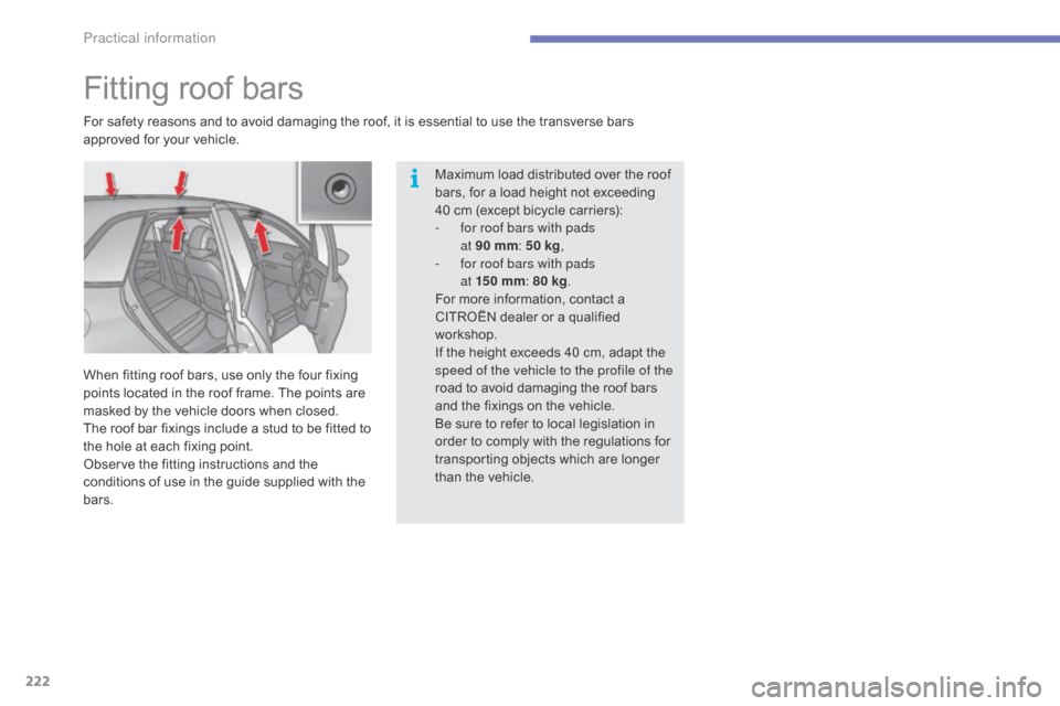
For safety reasons and to avoid damaging the roof, it is essential to use the transverse bars approved for your vehicle.
When
fitting roof bars, use only the four fixing
p
oints located in the roof frame. The points are
m
asked by the vehicle doors when closed.
The
roof bar fixings include a stud to be fitted to
t
he hole at each fixing point.
Observe
the fitting instructions and the
c
onditions of use in the guide supplied with the
b
ars. Maximum
load distributed over the roof
b
ars, for a load height not exceeding
4
0 cm (except bicycle carriers):
-
f
or roof bars with pads
at 90
mm:
50 kg,
-
f
or roof bars with pads
at 15 0
mm:
80 kg.
For
more information, contact a
C
ITROËN dealer or a qualified
w
orkshop.
If
the height exceeds 40 cm, adapt the
s
peed of the vehicle to the profile of the
road
to avoid damaging the roof bars
a
nd the fixings on the vehicle.
Be
sure to refer to local legislation in
o
rder to comply with the regulations for
t
ransporting objects which are longer
t
han the vehicle.
Practical information
Page 225 of 396
223
C4-2_en_Chap07_infos-pratiques_ed02-2015
Bonnet
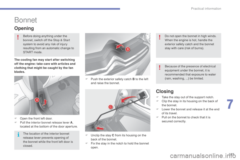
F Push the exterior safety catch B to the left
and raise the bonnet.
Opening
F Open the front left door.
F P ull the interior bonnet release lever A,
located
at the bottom of the door aperture.
F
U
nclip the stay C from its housing on the
b
ack of the bonnet.
F
F
ix the stay in the notch to hold the bonnet
ope
n.
Closing
F Take the stay out of the support notch.
F C lip the stay in its housing on the back of
t
he bonnet.
F
L
ower the bonnet and release it at the end
of
its travel.
F
P
ull on the bonnet to check that it is
s
ecured
c
orrectly.
The cooling fan may star t after switching
off the engine: take care with ar ticles and
clothing that might be caught by the fan
blades.
Before
doing
anything
under
the
b
onnet, switch off the Stop & Start
system
to
avoid
any
risk
of
injury
r
esulting
from
an
automatic
c
hange
t
o
S
TART
mode.
Do not open the bonnet in high winds.
When the engine is hot, handle the
e
xterior safety catch and the bonnet
s
tay with care (risk of burns).
Because of the presence of electrical
equipment under the bonnet, it is
r
ecommended that exposure to water
(
rain,
w
ashing, ...) be limited.
The location of the interior bonnet
release
lever
prevents
opening
of
t
he bonnet while the front left door is
closed.
7
Practical information
Page 226 of 396
224
C4-2_en_Chap07_infos-pratiques_ed02-2015
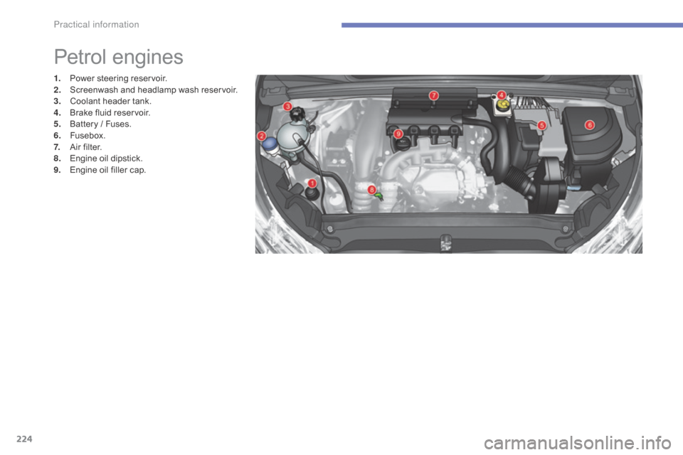
Petrol engines
1. Power steering r eservoir.
2. S creenwash and headlamp wash reservoir.
3.
C
oolant header tank.
4.
B
rake fluid reservoir.
5.
B
attery / Fuses.
6.
F
usebox.
7.
A
ir filter.
8.
E
ngine oil dipstick.
9.
E
ngine oil filler cap.
Practical information
Page 227 of 396
225
C4-2_en_Chap07_infos-pratiques_ed02-2015
* According to engine.
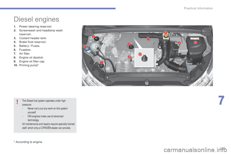
Diesel engines
1. Power steering r eservoir.
2. S creenwash and headlamp wash
reservoir.
3.
C
oolant header tank.
4.
B
rake fluid reservoir.
5.
B
attery / Fuses.
6.
F
usebox.
7.
A
ir filter.
8.
E
ngine oil dipstick.
9.
E
ngine oil filler cap.
10.
P
riming
pu
mp*.
The Diesel fuel system operates under high pressure:
- Never carry out any work on this system y
ourself.
- HDi engines make use of advanced t
echnology.
All
maintenance and repairs require specially trained
s
taff, which only a CITROËN dealer can provide.
7
Practical information
Page 228 of 396
226
C4-2_en_Chap07_infos-pratiques_ed02-2015
Checking levels
The check is carried out either when the ignition is switched on using the
o
il level indicator in the instrument
p
anel for vehicles so equipped, or
u
sing the dipstick.
Engine oil level
Checking using
the dipstick
Check all of these levels regularly, in line with the manufacturer's service schedule. Top them up if necessary, unless other wise indicated.
I f a level drops significantly, have the corresponding system checked by a CITROËN dealer or a qualified workshop.
It
is normal to top up the oil level between
t
wo services (or oil changes). CITROËN
r
ecommends that you check the level, and top
u
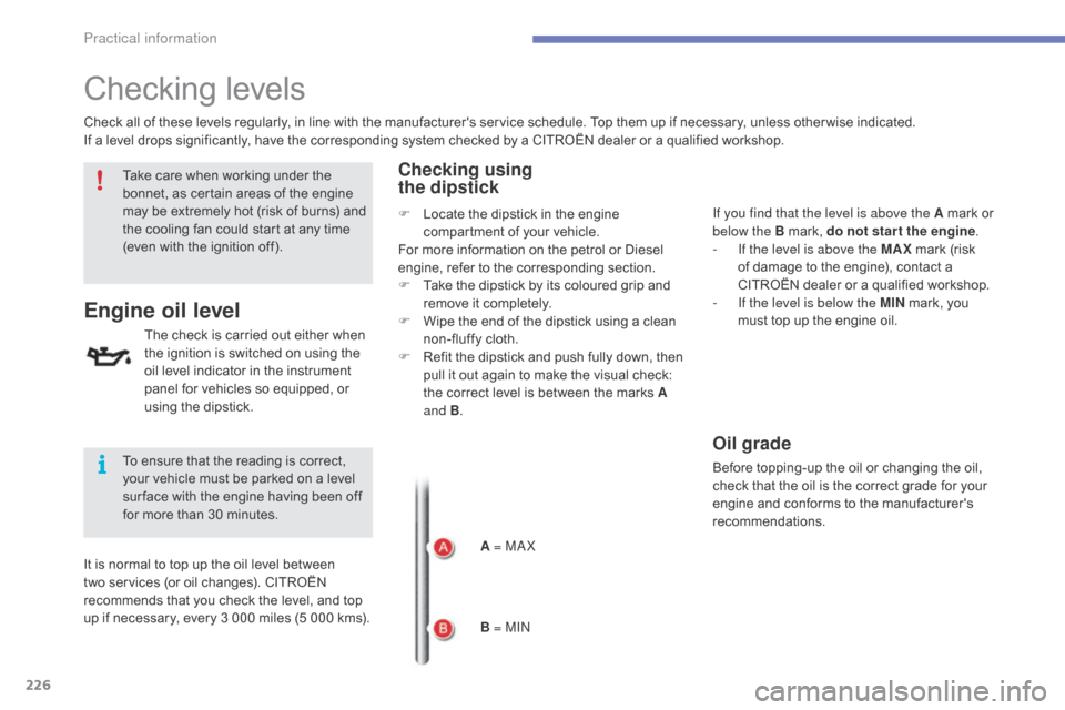
p if necessary, every 3 000 miles (5 000 kms).A = MA X
B = MIN If you find that the level is above the A
mark or
belo
w the B mark, do not star t the engine.
-
I
f the level is above the MAX
mark (risk
o
f damage to the engine), contact a
C
ITROËN dealer or a qualified workshop.
-
I
f the level is below the MIN
mark, you
m
ust top up the engine oil.
Oil grade
Before topping-up the oil or changing the oil, check that the oil is the correct grade for your
e
ngine and conforms to the manufacturer's
r
ecommendations.
Take
care
when
working
under
the
b
onnet,
as
certain
areas
of
the
engine
m
ay
be
extremely
hot
(risk
of
burns)
and
t
he
cooling
fan
could
start
at
any
time
(
even
with
the
ignition
off).
To
ensure
that
the
reading
is
correct,
y
our
vehicle
must
be
parked
on
a
level
s
ur face
with
the
engine
having
been
off
f
or
more
than
30
minutes. F
L
ocate
the
dipstick
in
the
engine
c
ompartment
of
your
vehicle.
For
more
information
on
the
petrol
or
Diesel
e
ngine,
refer
to
the
corresponding
section.
F
T
ake
the
dipstick
by
its
coloured
grip
and
r
emove
it
completely.
F
W
ipe
the
end
of
the
dipstick
using
a
clean
n
on-fluffy
cloth.
F
R
efit
the
dipstick
and
push
fully
down,
then
p
ull
it
out
again
to
make
the
visual
check:
t
he
correct
level
is
between
the
marks
A
and B .
Practical information
Page 229 of 396
227
C4-2_en_Chap07_infos-pratiques_ed02-2015
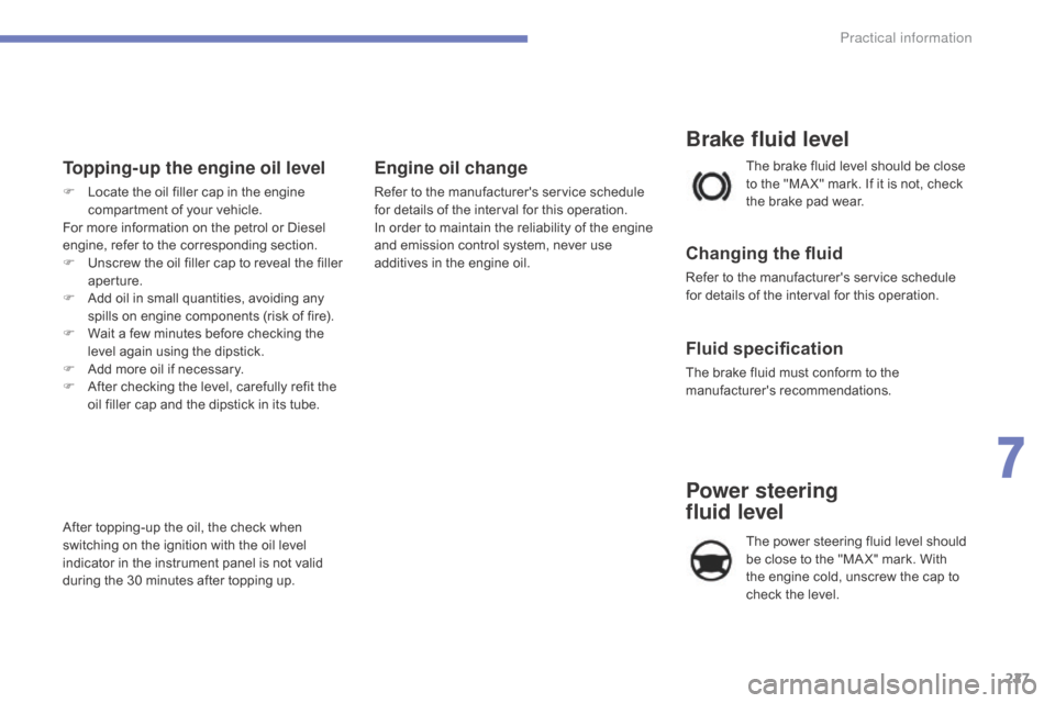
Topping-up the engine oil level
F Locate the oil filler cap in the engine c
ompartment of your vehicle.
For
more information on the petrol or Diesel
e
ngine, refer to the corresponding section.
F
U
nscrew the oil filler cap to reveal the filler
a
perture.
F
A
dd oil in small quantities, avoiding any
s
pills on engine components (risk of fire).
F
W
ait a few minutes before checking the
l
evel again using the dipstick.
F
A
dd more oil if necessary.
F
A
fter checking the level, carefully refit the
o
il filler cap and the dipstick in its tube.
After
topping-up the oil, the check when
s
witching on the ignition with the oil level
i
ndicator in the instrument panel is not valid
d
uring the 30 minutes after topping up.
Engine oil change
Refer to the manufacturer's service schedule for details of the interval for this operation.
In
order to maintain the reliability of the engine
a
nd emission control system, never use
a
dditives in the engine oil.
Brake fluid level
Changing the fluid
Refer to the manufacturer's service schedule for details of the interval for this operation.
Fluid specification
The brake fluid must conform to the manufacturer's r ecommendations.
The
brake fluid level should be close
t
o the "MA X" mark. If it is not, check
t
he brake pad wear.
Power steering
fluid level
The power steering fluid level should b
e close to the "MA X" mark. With
t
he engine cold, unscrew the cap to
c
heck the level.
7
Practical information
Page 230 of 396
228
C4-2_en_Chap07_infos-pratiques_ed02-2015
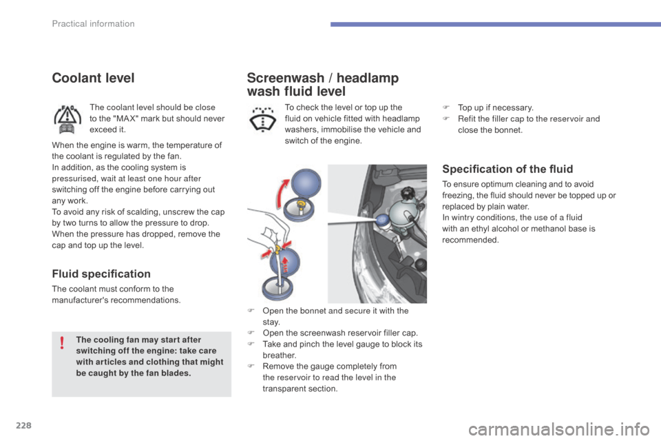
Screenwash / headlamp
wash fluid level
Specification of the fluid
To ensure optimum cleaning and to avoid freezing, the fluid should never be topped up or r
eplaced by plain water.
In wintry conditions, the use of a fluid
with
an ethyl alcohol or methanol base is
re
commended.
To
check
the
level
or
top
up
the
f
luid
on
vehicle
fitted
with
headlamp
w
ashers,
immobilise
the
vehicle
and
s
witch
of
the
engine.
F
O
pen the bonnet and secure it with the
st ay.
F
O
pen
the
screenwash
reservoir
filler
cap.
F
T
ake
and
pinch
the
level
gauge
to
block
its
b
reather.
F
R
emove
the
gauge
completely
from
t
he reservoir to read the level in the
transparent
s
ection.
Coolant level
The coolant level should be close
to the "MA X" mark but should never
e
xceed it.
Fluid specification
The coolant must conform to the manufacturer's r ecommendations.
The cooling fan may star t after
switching off the engine: take care
with articles and clothing that might
be caught by the fan blades.
When
the engine is warm, the temperature of
t
he coolant is regulated by the fan.
In addition, as the cooling system is
p
ressurised, wait at least one hour after
switching off the engine before carrying out
any work.
To avoid any risk of scalding, unscrew the cap
b
y two turns to allow the pressure to drop.
W
hen the pressure has dropped, remove the
c
ap and top up the level. F
T
op up if necessary.
F
R
efit the filler cap to the reservoir and
close the bonnet.
Practical information