Citroen C4 PICASSO RHD 2014.5 1.G Owner's Manual
Manufacturer: CITROEN, Model Year: 2014.5, Model line: C4 PICASSO RHD, Model: Citroen C4 PICASSO RHD 2014.5 1.GPages: 428, PDF Size: 10.03 MB
Page 281 of 428

279
Lamps on the tailgateModel with LED lamps
Model with conventional bulb lamps
Identify
the
failed
bulb.
F
O
pen
the
boot.
F
R
emove
the
access
cover. F
R
emove
the
three
lamp
fixing
screws
A .
F
D
isconnect
the
lamp
connector.
F
C
arefully
r
emove
t
he
l
amp
f
rom
i
ts
h
ousing.
F
T
urn
the
bulb
holder
a
quarter
of
a
turn
a
nti-clockwise
and
pull
the
bulb
out.
F
C
hange
the
bulb.
For
reassembly,
carry
out
these
operations
in
r
everse
o
rder.
7
Practical information
Page 282 of 428

280
Direction indicator, sidelamp and
foglamp
Access is by passing a hand under the bumper.
F T urn the bulb holder a quarter of a turn and
p
ull it out.
F
C
hange the bulb.
For
reassembly carry out these operations in
r
everse
o
rder.
You
can also contact a CITROËN dealer or a
q
ualified workshop for the replacement of these
b
ulbs. For
the replacement of this type of lamp, c
ontact a CITROËN dealer or a qualified
w
orkshop.
Third brake lamp (light emitting
diodes-LED)Number plate lamps (W5W)
To refit, press on the lens to clip it in place.
F
I
nsert a thin screwdriver into one of the
c
utouts in the the lens.
F
P
ush it outwards to unclip it.
F
R
emove the lens.
F
C
hange the faulty bulb.
Practical information
Page 283 of 428

281
Before changing a fuse:
F t he cause of the failure must be identified
a
nd
r
ectified,
F
a
ll electrical consumers must b switched
o
f f,
F
t
he vehicle must be immobilised with the
ig
nition
o
ff,
F
i
dentify the failed fuse using the tables and
l
ayout drawings in the following pages.
Changing a fuse
GoodFailed
The replacement of a fuse not shown in
t
he tables below may cause a serious
m
alfunction of your vehicle. Contact
a
CITROËN dealer or a qualified
w
orkshop. Tw e e z e r
Changing a fuse
The extraction tweezer is located in the d
ashboard f usebox c ompartment.
For
access to it:
F
o
pen the glove box,
F
u
nclip the cover by pulling at the top left,
t
hen right,
F
d
isengage the cover completely, by
c
arefully pulling in the direction indicated
b
y the arrow,
F
r
emove the tweezer.
Access to the tools
To replace a fuse, you must:
F u se the special tweezer to extract the fuse
f
rom its housing and check the condition of
it
s
f
ilament.
F
a
lways replace the failed fuse with a fuse
o
f the same rating (same colour); using a
d
ifferent rating could cause faults (risk of
f
i r e).
If
the fuse fails again soon after replacement,
h
ave the vehicle's electrical system checked by
a
CITROËN dealer or a qualified workshop.
7
Practical information
Page 284 of 428

282
CITRoËn will not accept responsibility
for the cost incurred in repairing your
v
ehicle or for rectifying malfunctions
r
esulting from the installation of
a
ccessories not supplied and not
r
ecommended by CITROËN and
n
ot installed in accordance with its
in
structions, in particular when the
combined
consumption of all of the
a
dditional equipment connected
e
xceeds
1
0
mil
liamperes.
Installing electrical
accessories
Your vehicle's electrical system is designed to operate with standard or
o
ptional
e
quipment.
Before
installing other electrical
e
quipment or accessories on your
v
ehicle, contact a CITROËN dealer or a
q
ualified
w
orkshop.
Configurations
The type of electrical system of the vehicle depends on its level of equipment.
T o identify the type of electrical system on your vehicle, open the bonnet: the presence of an
a
dditional fusebox in front of the battery indicates that it is type 2.
The
type 1 electrical system does not have any fuses in front of the battery.
Practical information
Page 285 of 428

283
Type 1 fuse tables
Fusebox 1
Dashboard fuses
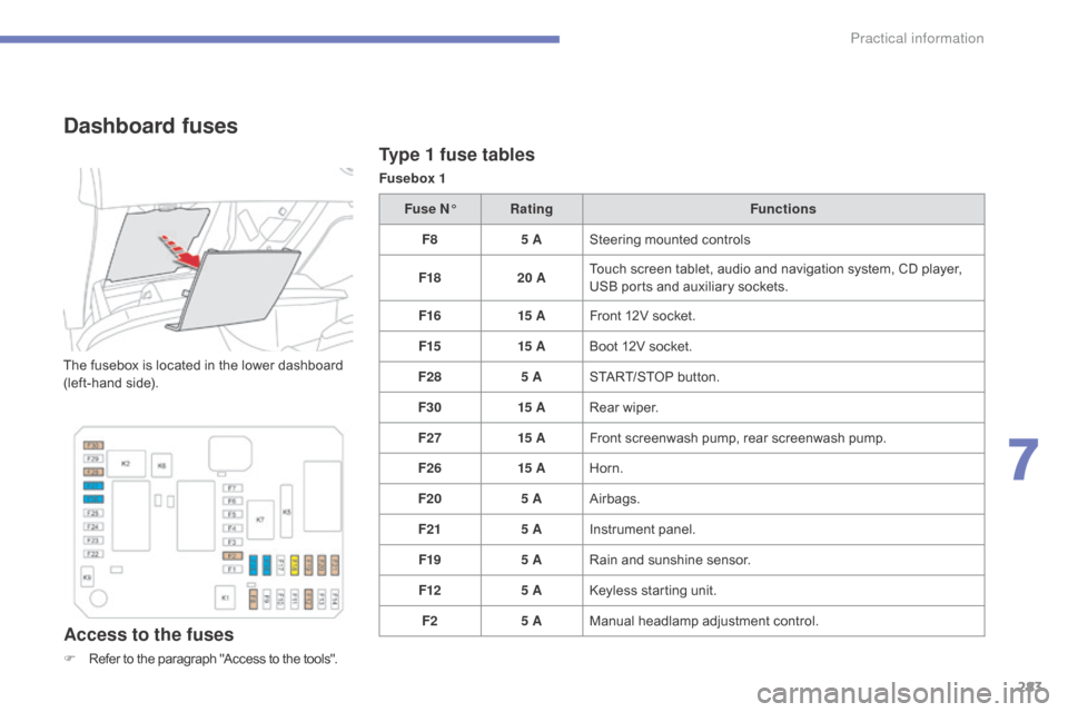
The fusebox is located in the lower dashboard (left-hand side).
Access to the fuses
F Refer to the paragraph "Access to the tools".Fuse N°
Rating Functions
F8 5 ASteering mounted controls
F18 20 ATouch screen tablet, audio and navigation system, CD player,
U
SB ports and auxiliary sockets.
F16 15 AFront 12V socket.
F15 15 ABoot 12V socket.
F28 5 ASTART/STOP button.
F30 15 ARear wiper.
F27 15 AFront screenwash pump, rear screenwash pump.
F26 15 AHorn.
F20 5 AAirbags.
F21 5 AInstrument panel.
F19 5 ARain and sunshine sensor.
F12 5 AKeyless starting unit.
F2 5 AManual
h
eadlamp
a
djustment
c
ontrol.
7
Practical information
Page 286 of 428

284
Fusebox 2Fuse N° Rating Functions
F9 15 ARear
12V socket.
Practical information
Page 287 of 428

285
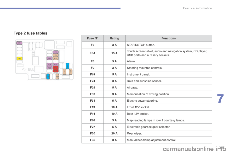
Type 2 fuse tables
Fuse N°Rating Functions
F3 3 ASTART/STOP
button.
F6 A 15 ATouch
screen tablet, audio and navigation system, CD player,
U
SB ports and auxiliary sockets.
F8 5 AAlarm.
F9 3 ASteering
mounted controls.
F19 5 AInstrument
panel.
F24 3 ARain
and sunshine sensor.
F25 5 AAirbags.
F33 3 AMemorisation
o
f
d
riving
p
osition.
F34 5 AElectric
power steering.
F13 10 AFront
12V socket.
F14 10 ABoot
12V socket.
F16 3 AMap
reading lamps in row 1 courtesy lamps.
F27 5 AElectronic
gearbox gear selector.
F30 20 ARear
wiper.
F38 3 AManual
h
eadlamp
a
djustment
c
ontrol.
7
Practical information
Page 288 of 428

286
Engine compartment fuses
An additional fusebox is fitted in front of the battery, for type 2.
The
fusebox
is
placed
in
the
engine
c
ompartment
near
the
battery
(left-hand
side).Access to the fuses
F Unclip the cover, by pushing the two red l
atches towards the rear of the vehicle.
F
C
hange the fuse (see corresponding
par
agraph).
F
W
hen you have finished, close the cover
c
arefully to ensure correct sealing of the
f
usebox.
Practical information
Page 289 of 428

287
Fuse N°Rating Functions
F18 10 ARight
hand main beam
F19 10 ALeft
hand main beam.
Type 2 fuse table
Fuse N°Rating Functions
F9 30 AMotorised
t
ailgate.
F18 25 AHi-Fi
amplifier.
F21 3 AHands-free
starting reader unit.
Type 1 fuse table
Fusebox 1
Fusebox 2Fuse N° Rating Functions
F19 30 AFront
wiper slow / fast speed.
F20 15 AFront
and rear screenwash pump.
F21 20 AHeadlamp
wash pump.
7
Practical information
Page 290 of 428

288
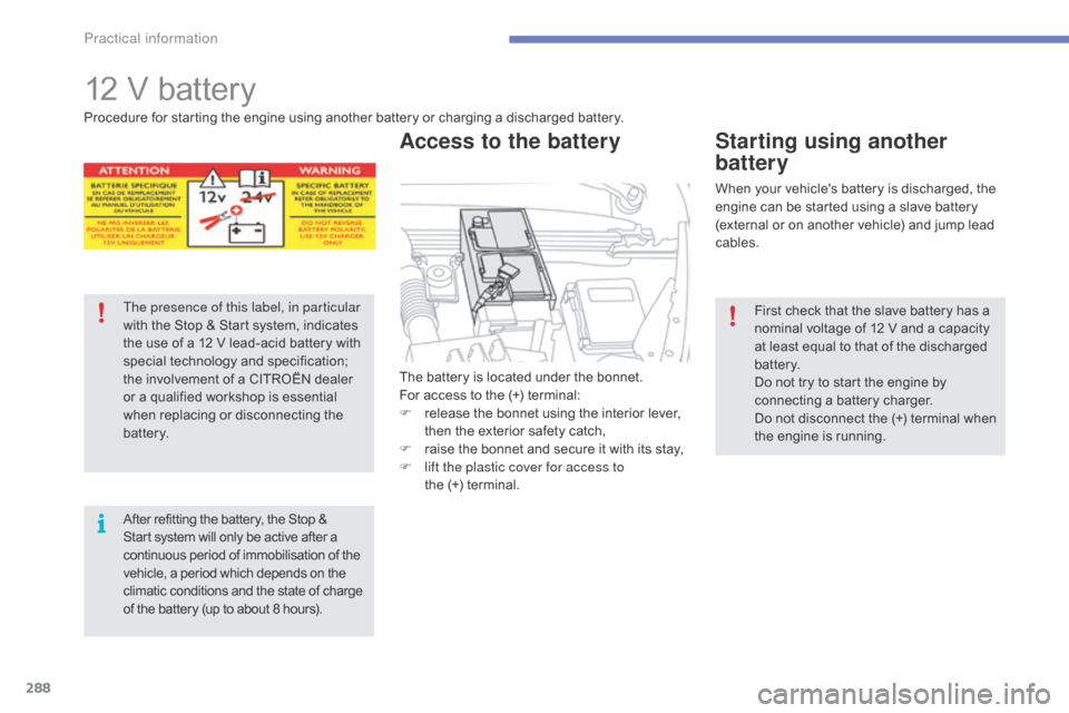
12 V battery
The battery is located under the bonnet.
F or access to the (+) terminal:
F
r
elease the bonnet using the interior lever,
t
hen the exterior safety catch,
F
r
aise the bonnet and secure it with its stay,
F
l
ift the plastic cover for access to
the
(+) terminal.
Access to the battery
Procedure for starting the engine using another battery or charging a discharged battery.
T he presence of this label, in particular
with
the Stop & Start system, indicates
t
he use of a 12 V lead-acid battery with
s
pecial
t
echnology
a
nd
s
pecification;
t
he involvement of a CITROËN dealer
o
r a qualified workshop is essential
w
hen replacing or disconnecting the
b
attery.
After
refitting the battery, the Stop &
S
tart system will only be active after a
c
ontinuous period of immobilisation of the
v
ehicle, a period which depends on the
c
limatic conditions and the state of charge
o
f the battery (up to about 8 hours). When
your vehicle's battery is discharged, the
e
ngine can be started using a slave battery
(
external or on another vehicle) and jump lead
c
ables.
Starting using another
battery
First check that the slave battery has a nominal voltage of 12 V and a capacity
a
t least equal to that of the discharged
b
attery.
Do
not try to start the engine by
c
onnecting a battery charger.
Do
not disconnect the (+) terminal when
t
he engine is running.
Practical information