Citroen C4 RHD 2015 2.G Owner's Manual
Manufacturer: CITROEN, Model Year: 2015, Model line: C4 RHD, Model: Citroen C4 RHD 2015 2.GPages: 328, PDF Size: 12.72 MB
Page 191 of 328
1111
189
CHANGING A WHEEL
Procedure for changing a faulty wheel for
the spare wheel using the tools pro -
vided
with the vehicle.
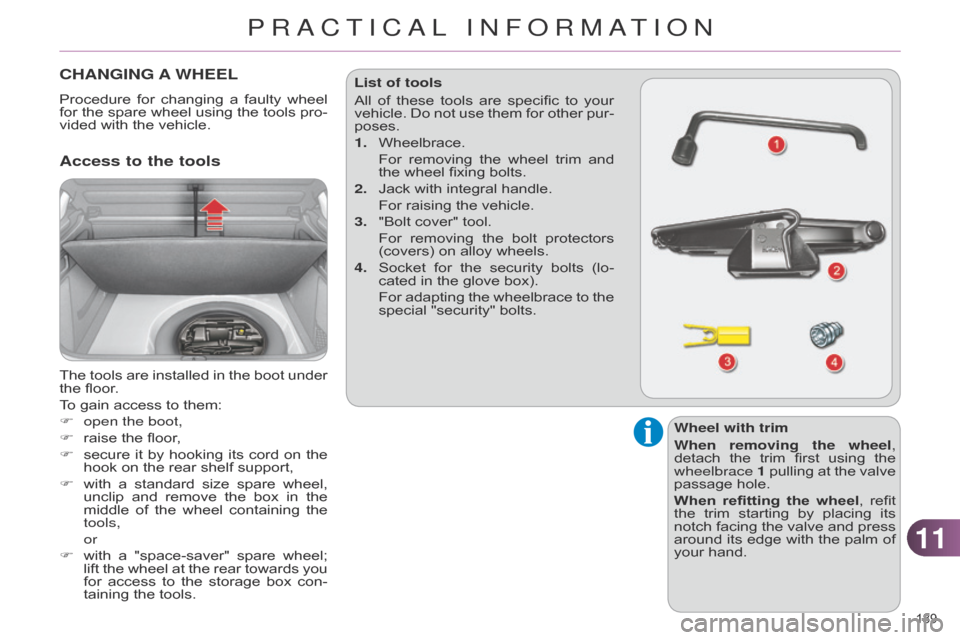
Access to the tools
The tools are installed in the boot under the
floor.
To
gain access to them:
F
open the boot,
F
raise
the floor,
F
secure
it
by
hooking
its
cord
on
the
hook
on the rear shelf support,
F
with
a
standard
size
spare
wheel,
unclip
and
remove
the
box
in
the
middle
of
the
wheel
containing
the
tools,
or
F
with
a
"space-saver"
spare
wheel;
lift
the
wheel
at
the
rear
towards
you
for
access
to
the
storage
box
con
-
taining
the tools. List of tools
All
of
these
tools
are
specific
to
your
vehicle.
Do
not
use
them
for
other
pur
-
poses.
1.
Wheelbrace.
For
removing
the
wheel
trim
and
the
wheel fixing bolts.
2.
Jack
with integral handle.
For
raising the vehicle.
3.
"Bolt
cover" tool.
For
removing
the
bolt
protectors
(covers)
on alloy wheels.
4.
Socket
for
the
security
bolts
(lo
-
cated in the glove box).
For
adapting
the
wheelbrace
to
the
special
"security" bolts.
Wheel with trim
When removing the wheel,
detach
the
trim
first
using
the
wheelbrace 1
pullin
g
at
the
valve
passage
hole.
When refitting the wheel,
refit
the
trim
starting
by
placing
its
notch
facing
the
valve
and
press
around
its
edge
with
the
palm
of
your
hand.
PRACTICAL INFORMATION
Page 192 of 328
1111
190
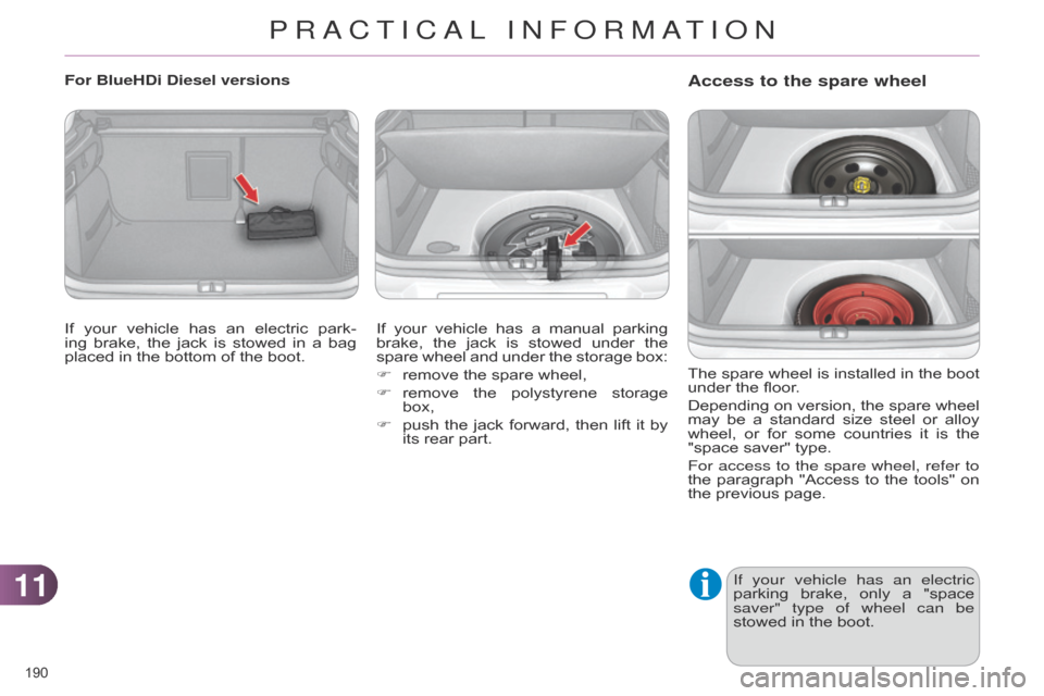
Access to the spare wheel
The spare wheel is installed in the boot under
the floor.
Depending
on
version,
the
spare
wheel
may
be
a
standard
size
steel
or
alloy
wheel,
or
for
some
countries
it
is
the
"space
saver" type.
For access to the spare wheel, refer to
the
paragraph
"Access
to
the
tools"
on
the
previous page.
If your vehicle has an electric
parking
brake,
only
a
"space
saver" type of wheel can be
stowed
in the boot.
For BlueHDi Diesel versions
If
your
vehicle
has
an
electric
park
-
ing
brake,
the
jack
is
stowed
in
a
bag
placed
in
the
bottom
of
the
boot. If
your
vehicle
has
a
manual
parking
brake,
the
jack
is
stowed
under
the
spare
wheel
and
under
the
storage
box:
F
remove
the
spare
wheel,
F
remove
the
polystyrene
storage
box,
F
push
the
jack
forward,
then
lift
it
by
its
rear
part.
PRACTICAL INFORMATION
Page 193 of 328

1111
191
Putting the standard wheel back in
placeTyre under-inflation detection
The
spare
wheel
is
not
fitted
with
a
sensor
.
The
punctured
wheel
must
be
repaired
by
a
CITROËN
dealer
or aqualified workshop.
Taking out the standard wheel
F
Put
the wheel back in its housing.
F
Unscrew
the
yellow
central
bolt
by
a
few turns then put it in place in the
centre
of the wheel.
F
T
ighten
fully
until
the
central
bolt
clicks
to retain the wheel correctly.
F
Unscrew
the
yellow
central
bolt.
F
Raise
the
spare
wheel
towards
you
from
the
rear.
F
T
ake
the
wheel
out
of
the
boot. F
Put
the
box
back
in
place
in
the
cen
-
tre
of the wheel and clip it.
PRACTICAL INFORMATION
Page 194 of 328

1111
192
Ensure that the jack is stable. If the
ground is slippery or loose,
the
jack
may
slip
or
drop
-
Risk
of
injury!
Removing a wheel
Parking the vehicle
Immobilise
the
vehicle
where
it
does
not
block
traffic:
the
ground
must
be
level,
stable
and
non-
slippery
ground.
Apply
the
parking
brake
unless
it has
been
programmed
to
auto
-
matic
mode,
switch
of
f
the
ignition and
engage
first
gear*
to
lock
the wheels.
Check
that
the
braking
warning
lamps
in
the
instrument
panel
are
on (not flashing).
The
occupants
must
get
out
of
the
vehicle
and
wait
where
they
are
safe.
If
necessary
,
place
a
chock
un
-
der
the
wheel
diagonally
oppo
-
site
the wheel to be changed.
Never
go
underneath
a
vehicle
raised
using
a
jack;
use
an
axle
stand. *
position R
for
an
electronic
gearbox;
P
for an automatic gearbox.
List of operations
F
Extend
the
jack
2
until
its
head
comes
into
contact
with
the
jacking
point A
or B
used;
the
contact
sur
-
face A or B
on
the
vehicle
must
be
engaged
with
the
central
part
of
the
head
of the jack.
F
Raise
the
vehicle
until
there
is
suffi
-
cient
space
between
the
wheel
and
the
ground
to
admit
the
spare
(not
punctured)
wheel easily.
F
Remove the chromed bolt cover from
each of the bolts using the
tool
3 (according to equipment).
F
Fit
the
security
socket
4 on the wheel
-
brace 1
to slacken the security bolt.
F
Slacken
the
other
bolts
using
the
wheelbrace
1 only.
F
Place
the
foot
of
the
jack
2
on the
ground
and
ensure
that
it
is
directly
below the front
A or rear B
jacking
point
provided
on
the
underbody
,
whichever is closest to the wheel to
be
changed.
PRACTICAL INFORMATION
Page 195 of 328

1111
193
Fitting a steel or "space-
saver" spare wheel
If
your
vehicle
is
fitted
with
al
-
loy
wheels,
when
tightening
the
bolts
on
fitting
it
is
normal
to
notice
that
the
washers
do
not
come
into
contact
with
the
steel
or
"space-saver"
spare
wheel.
The
wheel
is
secured
by
the
conical
contact of each bolt.List of operations
F
Remove
the
bolts
and
store
them
in
a
clean
place.
F
Remove
the
wheel. F
Put the wheel in place on the hub.
F Screw in the bolts by hand to the
stop.
F
Pre-tighten
the
security
bolt
using
the wheelbrace
1
fitted
with
the
se
-
curity
socket 4.
F
Pre-tighten
the
other
bolts
using
the
wheelbrace
1 only.
Fitting a wheel
Take care to position the jack only at
one of the jacking points A
or B
under
the
vehicle,
ensuring
that the
head
of
the
jack
is
centred under
the
contact
surface
of
the vehicle.
Otherwise,
there
is
a
risk of
damage
to
the
vehicle
and/or the
jack dropping - Risk of injury!
PRACTICAL INFORMATION
Page 196 of 328
1111
194
After changing a wheel
To
store
the
punctured
wheel
in
the
boot
correctly
,
first
remove
the
central cover.
When
using
the
"space-saver"
type
spare
wheel,
do
not
exceed
50
mph (80 km/h).
Have
the
tightening
of
the
bolts
and
the
pressure
of
the
spare
wheel
checked
by
a
CITROËN
dealer
or
a
qualified
workshop
without
delay.
Have
the
punctured
wheel
re
-
paired
and
replace
it
on
the
ve
-
hicle
as soon as possible.
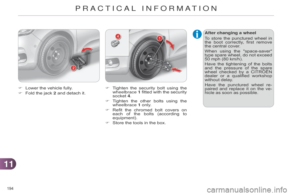
F
T
ighten
the
security
bolt
using
the
wheelbrace 1
fitted
with
the
security
socket
4.
F
T
ighten
the
other
bolts
using
the
wheelbrace
1
only.
F
Refit
the
chromed
bolt
covers
on
each
of
the
bolts
(according
to
equipment).
F
Store
the
tools
in
the
box.
F
Lower
the
vehicle
fully.
F
Fold
the
jack
2
and
detach
it.
PRACTICAL INFORMATION
Page 197 of 328
1111
195
SNOW CHAINS
In wintry conditions, snow chains im -
prove traction as well as the behaviour
of
the vehicle when braking. Advice on installation
F
If
you
have
to
fit
the
chains
during
a
journey
,
stop
the
vehicle
on
a
flat
surface
on the side of the road.
F
Apply
the
parking
brake
and
posi
-
tion
any
wheel
chocks
to
prevent
movement
of your vehicle.
F
Fit
the
chains
following
the
instruc
-
tions
provided by the manufacturer.
F
Move
of
f
gently
and
drive
for
a
few
moments,
without
exceeding
30 mph
(50 km/h).
F
Stop
your
vehicle
and
check
that
the snow
chains are correctly tightened.
The
snow
chains
must
be
fitted
only
to
the
front
wheels.
They
must
never
be
fitted
to
"space-
saver"
type spare wheels.
Take
account
of
the
legislation
in
force in your country on the use
of
snow
chains
and
the
maxi
-
mum
running speed authorised.Avoid
driving
with
snow
chains
on
roads
that
have
been
cleared
of
snow
,
to
avoid
damaging
your
vehicle's
tyres
and
the
road
sur
-
face.
If
your
vehicle
is
fitted
with
alloy
wheels,
check
that
no
part
of
the
chain
or
its
fixings
is
in
contact
with the wheel rim.
Use
only the chains designed to be fit -
ted to the type of wheel fitted to your
vehicle:
Original
tyre sizeMaximum
link
size.
195/65
R159
mm
205/55
R16
225/45
R17
225/40
R18
cannot be fitted with chains
For more information on snow chains, contact
a CITROËN dealer or a quali -
fied
workshop.
It
is
strongly
recommended
that
before you leave, you practise
fitting
the
snow
chains
on
a
level
and
dry surface.
PRACTICAL INFORMATION
Page 198 of 328
1111
196
CHANGING A BULB
The headlamps are fitted with polycarbonate
glass with a pro -
tective
coating:
F
do not clean them using a
dry or abrasive cloth,
nor
with a detergent or solvent
product,
F
use
a
sponge
and
soapy
wa
-
ter
or a pH neutral product,
F
when
using
a
high
pressure
washer
on
persistent
marks,
do
not
keep
the
lance
direct
-
ed
towards
the
lamps
or
their
edges
for
too
long,
so
as
not
to
damage
their
protective
coating
and seals.
Changing
a
bulb
should
only
be
done
after
the
headlamp
has
been
switched
of
f
for
several
minutes
(risk of serious burns).
F
Do
not
touch
the
bulb
directly
with
your
fingers,
use
a
lint-
free
cloth.
It
is
imperative
to
use
only
anti-
ultraviolet
(UV)
type
bulbs
to
avoid
damaging the headlamp.
Always
replace
a
failed
bulb
with
a
new
bulb
with
the
same
type
and
specification. Risk of electrocution
Xenon
bulbs
(D1S-35W)
must
be replaced
by
a
CITROËN
dealer or
a qualified workshop.
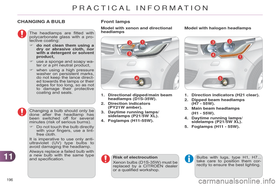
Front lamps
1. Direction indicators (H21 clear).
2.
Dipped beam headlamps
(H7 - 55W).
3.
Main beam headlamps
(H1 - 55W).
4.
Daytime running lamps/
sidelamps (P21/5W XL).
5.
Foglamps (H1
1 - 55W).
1.
Directional dipped/main beam
headlamps (D1S-35W).
2.
Direction indicators
(PY21W
amber).
3.
Daytime running lamps/
sidelamps (P21/5W XL).
4.
Foglamps (H1
1-55W). Model with halogen headlamps
Model with xenon and directional
headlamps
Bulbs with lugs, type H1, H7... take
care to position them cor -
rectly
to ensure the best lighting.
PRACTICAL INFORMATION
Page 199 of 328

1111
197
Amber coloured bulbs, such as the
direction indicators, must be
replaced
with
bulbs
of
identical
specifications
and colour.
When
refitting,
close
the
protec
-
tive cover carefully to preserve
the
sealing of the headlamp.
Changing direction indicator bulbs
Model with halogen headlamps
Rapid
flashing
of
the
direction
indicator
warning
lamp
(right
or
left)
indicates
the
failure
of
a
bulb
on
that
side.
Access to bulbs
F
Remove
the
air
deflector
by
unclip
-
ping
each
of
its
three
attachment
points.
F
Unclip
the
bonnet
release
cable
at
its
two
fixings.
F
Move
the
cable
down.
After
changing
the
failed
bulb,
remember to
put
everything
back
in
place
(cable
and air
deflector).
Depending
on
the
engine
and
only
on
the
left
hand
side,
you
must
first
carry
out
the
following
operations
for
access
to
the
protective
covers
on
the
bulbs.
F
T
urn
the
bulb
holder
a
quarter
of
a
turn
and
extract
it.
F
Pull
out
the
bulb
and
change
it.
To
reassemble,
carry
out
these
opera
-
tions
in
reverse
order. Model with Xenon headlamps
F
Remove
the
protective
cover
by
pullin
g on its tongue.
F
Disconnect
the electrical connector.
F
Separate
the
springs
to
release
the
bulb.
F
Pull
the bulb out and replace it.
To
reassemble,
carry
out
these
opera
-
tions
in reverse order.
PRACTICAL INFORMATION
Page 200 of 328
1111
198
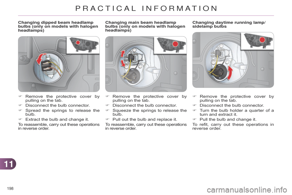
Changing dipped beam headlamp
bulbs (only on models with halogen
headlamps)Changing daytime running lamp/
sidelamp bulbs
F
Remove
the
protective
cover
by
pullin
g on the tab.
F
Disconnect
the bulb connector.
F
T
urn
the
bulb
holder
a
quarter
of
a
turn
and extract it.
F
Pull
the bulb and change it.
To
refit,
carry
out
these
operations
in
reverse
order.
F
Remove
the
protective
cover
by
pullin
g on the tab.
F
Disconnect
the bulb connector.
F
Spread
the
springs
to
release
the
bulb.
F
Extract
the bulb and change it.
To
reassemble,
carry
out
these
operations in
reverse order. Changing main beam headlamp
bulbs (only on models with halogen
headlamps)
F
Remove
the
protective
cover
by
pullin
g on the tab.
F
Disconnect
the bulb connector.
F
Squeeze
the
springs
to
release
the
bulb.
F
Pull
out the bulb and replace it.
To
reassemble,
carry
out
these
operations in
reverse order.
PRACTICAL INFORMATION