ESP CITROEN DS4 2023 Service Manual
[x] Cancel search | Manufacturer: CITROEN, Model Year: 2023, Model line: DS4, Model: CITROEN DS4 2023Pages: 296, PDF Size: 9.91 MB
Page 159 of 296

157
Detection may be impeded:
- i f the sensors are dirty (mud, snow...),
-
i
f the road markings are not clearly
visible,
-
i
f there is little contrast between the
markings on the road and the road
sur face.Blind spot monitoring
This driving assistance system warns the driver
of the presence of another vehicle in the blind
spot angle of their vehicle (areas hidden from
the driver's field of vision), as soon as this
presents a potential danger. This system is designed to improve safety
when driving and is in no circumstances
a substitute for the use of the interior rear
view mirror and door mirrors. It is the
driver's responsibility to constantly check
the traffic, to assess the distances and
relative speeds of other vehicles and to
predict their movements before deciding
whether to change lane.
The blind spot monitoring system can
never replace the need for vigilance on the
part of the driver.
A warning lamp appears in the door mirror on
the side in question:
- i
mmediately, when being overtaken,
- a fter a delay of about one second, when
overtaking a vehicle slowly.
06
Driving
Page 164 of 296

162
Tyre under-inflation
d
etection
The tyre under-inflation detection system
is an aid to driving which does not replace
the need for vigilance on the part of the
driver. This system does not avoid the need to
check the tyre pressures (including the
spare wheel) every month as well as
before a long journey.
Driving with under-inflated tyres worsens
road-holding, lengthens braking distances,
causes premature wear of the tyres,
particularly in adverse conditions (heavy
loads, high speeds, long journeys).
Driving with under-inflated tyres
increases fuel consumption.
The inflation pressures defined for your
vehicle can be found on the tyre pressure
label.
Tyre pressure should be checked when
the tyres are "cold" (vehicle stopped for
1 hour or after a journey of less than
6 miles (10 km) at moderate speeds).
Other wise, add 0.3 bar to the values
indicated on the label.
For more information on Identification
markings , including the tyre pressure
label, refer to the corresponding section.
Under-inflation alert
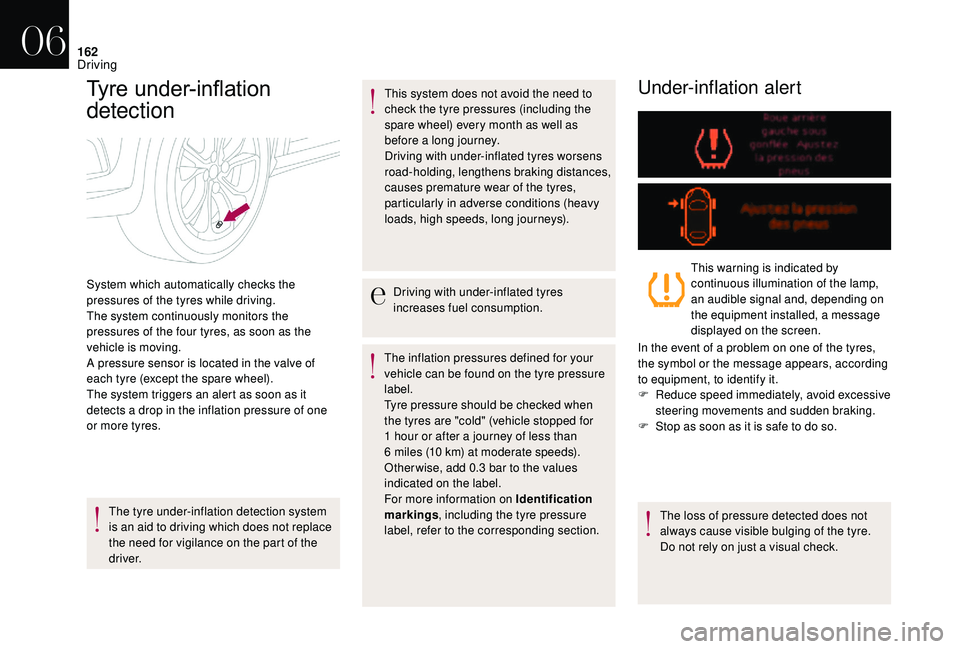
System which automatically checks the
pressures of the tyres while driving.
The system continuously monitors the
pressures of the four tyres, as soon as the
vehicle is moving.
A pressure sensor is located in the valve of
each tyre (except the spare wheel).
The system triggers an alert as soon as it
detects a drop in the inflation pressure of one
or more tyres. This warning is indicated by
continuous illumination of the lamp,
an audible signal and, depending on
the equipment installed, a message
displayed on the screen.
In the event of a problem on one of the tyres,
the symbol or the message appears, according
to equipment, to identify it.
F
R
educe speed immediately, avoid excessive
steering movements and sudden braking.
F
S
top as soon as it is safe to do so.
The loss of pressure detected does not
always cause visible bulging of the tyre.
Do not rely on just a visual check.
06
Driving
Page 168 of 296

166
Fuel
Tank capacity: approximately 60 litres.
Low fuel level
When the low fuel level is reached
in the tank, this warning lamp
comes on in the instrument panel,
accompanied by an audible warning
and the display of an alert message.
When it first comes on, about
6 litres of fuel is left in the tank.
Until sufficient fuel has been added, every time
the ignition is switched on, this warning lamp
appears, accompanied by an audible signal
and an alert message. When driving, this
audible signal and alert message are repeated
with increasing frequency, as the level drops
towards 0 .
You must refuel as soon as possible to avoid
running out of fuel.
If you run out of fuel (Diesel), refer to the
corresponding section.
Refuelling
Additions of fuel must be of at least 5 litres, in
order to be registered by the fuel gauge. With Stop & Start, never refuel with the
system in STOP mode; you must switch
off the ignition with the key, or the START/
STOP button if your vehicle has Keyless
Entry and Starting.
Opening the filler cap may create a noise
caused by an inrush of air. This vacuum is
entirely normal, resulting from the sealing of the
fuel system.
F
P
ress this button until the automatic
opening of the fuel flap is heard.
This control remains active for a few minutes after switching off the ignition. If necessary,
switch the ignition on again to reactivate it.
F
T
ake care to select the pump that delivers
the correct type of fuel for your vehicle. F
I
ntroduce the nozzle so as to push in the
metal non-return flap.
F
M
ake sure that the nozzle is pushed in as
far as possible before starting to refuel (risk
of blowback).
F
H
old it in this position throughout the filling
operation.
F
P
ush the fuel flap to close it.
If you are filling your tank to the top, do not
persist after the third cut- off; this could
cause your vehicle to malfunction.
Your vehicle is fitted with a catalytic converter,
which helps to reduce the level of harmful
emissions in the exhaust gases.
For petrol engines, you must use unleaded
fuel.
The filler neck is narrower, allowing only
unleaded petrol nozzles to be introduced.
07
Practical information
Page 170 of 296

168
Compatibility of fuels
Fuel used for petrol engines
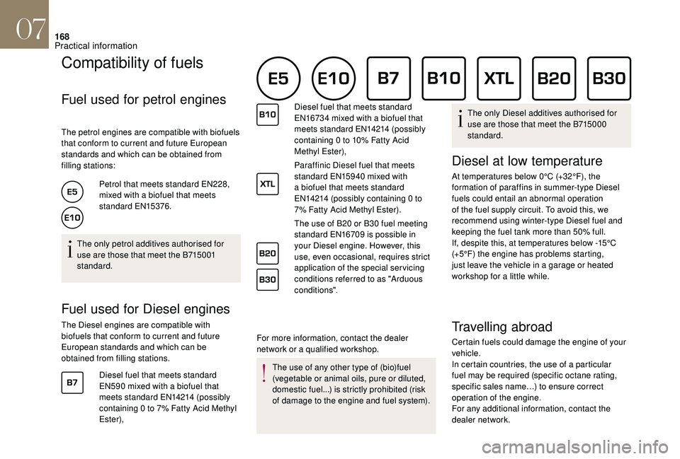
The petrol engines are compatible with biofuels
that conform to current and future European
standards and which can be obtained from
filling stations:Petrol that meets standard EN228,
mixed with a biofuel that meets
standard EN15376.
The only petrol additives authorised for
use are those that meet the B715001
standard.
Fuel used for Diesel engines
The Diesel engines are compatible with
biofuels that conform to current and future
European standards and which can be
obtained from filling stations. Diesel fuel that meets standard
EN590 mixed with a biofuel that
meets standard EN14214 (possibly
containing 0 to 7% Fatty Acid Methyl
Ester), For more information, contact the dealer
network or a qualified workshop.Diesel fuel that meets standard
EN16734 mixed with a biofuel that
meets standard EN14214 (possibly
containing 0 to 10% Fatty Acid
Methyl Ester),
Paraffinic Diesel fuel that meets
standard EN15940 mixed with
a biofuel that meets standard
EN14214 (possibly containing 0 to
7% Fatty Acid Methyl Ester).
The use of B20 or B30 fuel meeting
standard EN16709 is possible in
your Diesel engine. However, this
use, even occasional, requires strict
application of the special ser vicing
conditions referred to as "Arduous
conditions".
The use of any other type of (bio)fuel
(vegetable or animal oils, pure or diluted,
domestic fuel...) is strictly prohibited (risk
of damage to the engine and fuel system). The only Diesel additives authorised for
use are those that meet the B715000
standard.
Diesel at low temperature
At temperatures below 0°C (+32°F), the
formation of paraffins in summer-type Diesel
fuels could entail an abnormal operation
of the fuel supply circuit. To avoid this, we
recommend using winter-type Diesel fuel and
keeping the fuel tank more than 50% full.
If, despite this, at temperatures below -15°C
(+5°F) the engine has problems starting,
just leave the vehicle in a garage or heated
workshop for a little while.
Travelling abroad
Certain fuels could damage the engine of your
vehicle.
In certain countries, the use of a particular
fuel may be required (specific octane rating,
specific sales name…) to ensure correct
operation of the engine.
For any additional information, contact the
dealer network.
07
Practical information
Page 172 of 296

170
Very cold climate screen
(Depending on the country of sale.)
Removable protective screen which prevents
the accumulation of snow at the radiator
cooling fan.
Fitting
F Position the very cold climate screen to the front of the lower section of the front
b u m p e r.
F
P
ress around its edge to engage its fixing
clips one by one.
Removing
F Use a screwdriver as a lever to release each fixing clip.
The very cold climate screen must be
removed when:
-
t
he exterior temperature exceeds
10°C,
-
w
hen towing,
-
a
t speeds above 75 mph (120 km/h).
To w b a r
Your vehicle is primarily designed for
transporting people and luggage, but it may
also be used for towing a trailer.We recommend the use of genuine
DS AUTOMOBILES towbars and their
harnesses that have been tested and
approved from the design stage of your
vehicle, and that the fitting of the towbar
is entrusted to a dealer or a qualified
workshop.
If the towbar is not fitted by a dealer, it
must still be fitted in accordance with the
vehicle manufacturer's instructions. Driving with a trailer places greater
demands on the towing vehicle and the
driver must take particular care.
For more information on Driving advice
,
particularly when towing, refer to the
corresponding section.
Obser ve the maximum authorised towable
weight, indicated on your vehicle's
registration certificate, the manufacturer's
label as well as in the Technical data
section of this guide.
Complying with the maximum
authorised nose weight (towball)
also includes the use of accessories
(bicycle carriers, tow boxes, etc.).
The maximum authorised nose weight
does not depend on the type of device
installed, fixed or removable, with or
without a tool.
07
Practical information
Page 173 of 296

171
Towbar with quickly
detachable towball
Presentation
This towbar allows the towball to be fitted and
removed quickly and easily without the use of
tools. Installed behind the bumper, the device
is invisible after the towball has been removed
and the trailer harness carrier has been folded
away.
1. Carrier.
2. Protective plug.
3. Safety eye.
4. Folding trailer harness socket.
5. Detachable towball.
6. Locking/unlocking wheel.
7. Key-operated safety lock.
8. Locking wheel protector.
9. Ball protector.
10. Stowing bag.
A. Locked position
The locking wheel is not in contact with the
towball (gap of about 5 mm).
The green mark is visible.
The lock for the locking wheel is facing
rearward.
B. Unlocked position
The locking wheel is in contact with the towball.
The green mark is hidden.
The lock for the locking wheel is facing for ward. Obser ve the legislation in force in the
country in which you are driving.
For information on the maximum trailer
weight and the recommended nose
weight, refer to the Technical data section.
For more information on Towing a trailer
,
refer to the corresponding section.
Before each use
Check that the towball is correctly fitted,
verifying that:
-
t
he towball is correctly engaged
(position A ),
-
t
he safety lock is closed and the key
removed; the locking wheel can no
longer be operated,
-
t
he towball must not be able to move in
its carrier; test by shaking it with your
hand.
07
Practical information
Page 174 of 296

172
During use
Never release the locking system with a
trailer or load carrier on the towball.
Never exceed the gross train weight
(GTW) for the vehicle.
Before setting off, check the adjustment of
the headlamp beam height.
For more information on adjusting the
headlamp beam height, refer to the
corresponding section.
After use
For journeys made without a trailer or
load carrier, the trailer socket must be
folded away, the towball removed and the
protective plug inserted in the carrier. This
measure applies particularly if the towball
could hinder visibility of the number plate
or lighting.Fitting the towball
F Remove the protective plug from the carrier and check the condition of the fixing system.
If necessary, clean the carrier with a brush
or a clean cloth.
F
T
ake the towball from the storage bag.
F
R
emove the protective cover from the ball
and the protective cap from the locking
wheel.
F
S
tow the plug, cover and cap in the storage
bag.
F
C
heck that the towball is unlocked (position
B ). If not, insert the key in the lock and
turn the key anti-clockwise to unlock the
mechanism. F
T
ake the towball in both hands; insert the
end of the towball into the carrier by lifting it,
then, to ensure that it has correctly locked in
place, pull firmly down on the ball end of the
towball.
The locking wheel then automatically rotates
anti-clockwise with an audible "click". Take
care to keep your hands clear.
F
C
heck that the towball has correctly locked
in place (position A ).
07
Practical information
Page 177 of 296

175
Load reduction mode
System which manages the use of certain
functions according to the level of charge
remaining in the battery.
When the vehicle is being driven, the load
reduction function temporarily deactivates
certain functions, such as air conditioning,
heated rear screen...
The deactivated functions are reactivated
automatically as soon as conditions permit.
Energy saving mode
System that manages the duration of use of
certain functions to conser ve a sufficient level
of charge in the battery.
After the engine has stopped, you can
still use functions such as the audio
equipment, windscreen wipers, dipped
beam headlamps,
courtesy lamps, etc. for a
maximum combined period of thirty minutes.
This period may be greatly reduced if the
battery is not fully charged.
Switching to this mode
Once this period has elapsed, a message
appears in the screen indicating that the
vehicle has switched to the energy saving
mode and the active functions are put on
st a n d by.If the telephone was operated via
the touch screen at that moment, the
connection would be interrupted after
10
minutes.
Exiting the mode
These functions will be automatically restored
the next time the vehicle is used.
F
I
n order to restore the use of these functions
immediately, start the engine and let it run
for a few minutes.
The time available to you will then be double
the period for which the engine is left running.
However, this period will always be between
five and thirty minutes.
The engine will not start if the battery is
discharged.
For more information on the 12 V batter y ,
refer to the corresponding section.
07
Practical information
Page 178 of 296

176
Changing a wiper blade
Before removing a front wiper
F Within one minute after switching off the ignition, operate the wiper control stalk to
position the wiper blades in the middle of
the windscreen (maintenance position).
Removing
F Lift the corresponding wiper arm away from the windscreen.
F
U
nclip and remove the wiper blade.
FittingF Position and clip the new wiper blade to the arm.
F
C
arefully lower the wiper arm.
After reassembling a front
wiper
F Switch on the ignition.
F O perate the wiper lever again to park the
wiper blades.
Fitting roof bars
As a safety measure and to avoid
damaging the roof, it is essential to use
the transverse bars approved for your
vehicle. Follow the instructions for fitting
and use supplied with the roof bars.
Some models come fitted with longitudinal
bars. These are purely aesthetic.
Transverse bars must not be fitted to
these longitudinal bars.
When fitting roof bars, use only the four
anchorage points located in the roof frame.
The points are masked by the vehicle doors
when closed.
Remove the protective covers, levering them
off with a screwdriver. Be careful not to scratch
the paint.
The roof bar mountings include a stud which
should be fitted to the opening in each
anchorage point.
Keep the protective covers safe so that they
can be refitted after removing the roof bars.
07
Practical information
Page 181 of 296

179
Checking levels
Check all of these levels regularly, in line with
the manufacturer's service schedule. Top them
up if necessary, unless other wise indicated.
If a level drops significantly, have the
corresponding system checked by the dealer
network or a qualified workshop.The fluid must comply with the
manufacturer's recommendations and with
the vehicle's engine.
Take care when working under the
bonnet, as certain areas of the engine
may be extremely hot (risk of burns) and
the cooling fan could start at any time
(even
with the ignition off).
Used products
Avoid prolonged contact of used oil or
fluids with the skin.
Most of these fluids are harmful to health
or indeed very corrosive. Do not discard used oil or fluids into
sewers or onto the ground.
Return used oil to the dealer network or
a qualified workshop and dispose of it in
the containers reser ved for this purpose.
Engine oil level
The check is carried out either when
the ignition is switched on using the
oil level indicator in the instrument
panel for vehicles equipped with an
electric gauge, or using the dipstick.
To ensure that the reading is correct, your
vehicle must be parked on a level sur face
with the engine stopped for more than
30
minutes.
It is normal to top up the oil level between two
ser vices (or oil changes). We recommend that
you check the level, and top up if necessary,
every 3,000 miles (5,000 km).
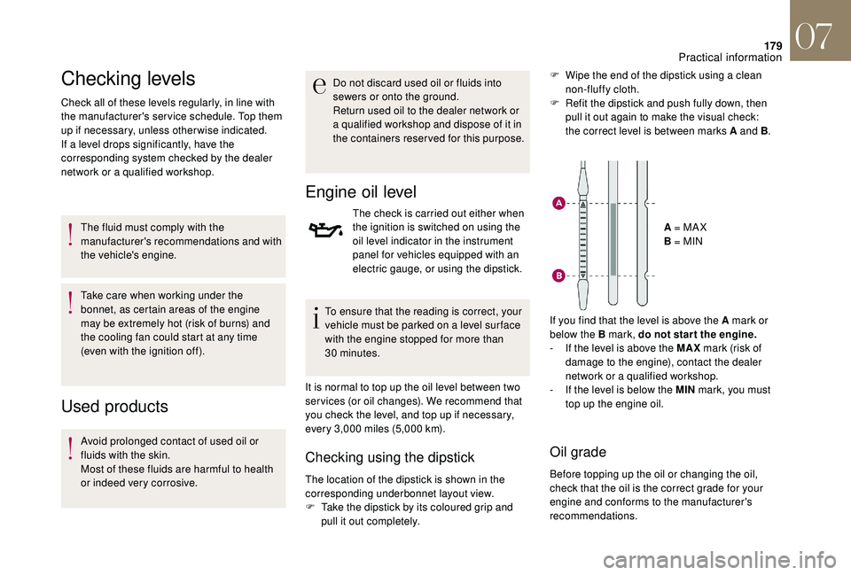
Checking using the dipstick
The location of the dipstick is shown in the
corresponding underbonnet layout view.
F
T
ake the dipstick by its coloured grip and
pull it out completely. A = MA X
B = MIN
If you find that the level is above the A mark or
below the B mark, do not star t the engine.
-
I
f the level is above the MAX
mark (risk of
damage to the engine), contact the dealer
network or a qualified workshop.
-
I
f the level is below the MIN
mark, you must
top up the engine oil.
Oil grade
Before topping up the oil or changing the oil,
check that the oil is the correct grade for your
engine and conforms to the manufacturer's
recommendations. F
W
ipe the end of the dipstick using a clean
non-fluffy cloth.
F
R
efit the dipstick and push fully down, then
pull it out again to make the visual check:
the correct level is between marks A and B .
07
Practical information