DAEWOO LACETTI 2004 Service Repair Manual
Manufacturer: DAEWOO, Model Year: 2004, Model line: LACETTI, Model: DAEWOO LACETTI 2004Pages: 2643, PDF Size: 80.54 MB
Page 1061 of 2643
4E1 – 4IREAR DISC BRAKES
DAEWOO V–121 BL4
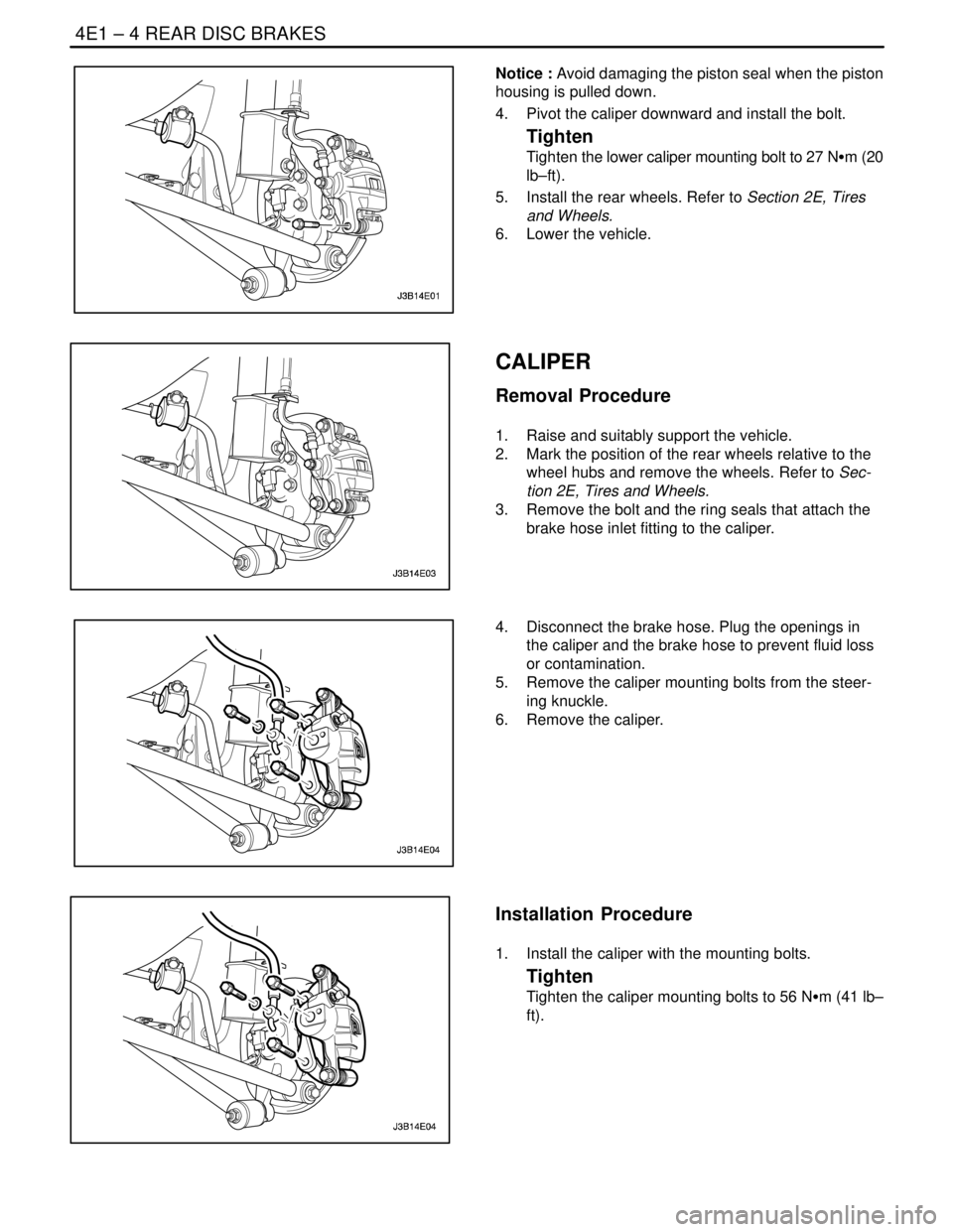
Notice : Avoid damaging the piston seal when the piston
housing is pulled down.
4. Pivot the caliper downward and install the bolt.
Tighten
Tighten the lower caliper mounting bolt to 27 NSm (20
lb–ft).
5. Install the rear wheels. Refer to Section 2E, Tires
and Wheels.
6. Lower the vehicle.
CALIPER
Removal Procedure
1. Raise and suitably support the vehicle.
2. Mark the position of the rear wheels relative to the
wheel hubs and remove the wheels. Refer to Sec-
tion 2E, Tires and Wheels.
3. Remove the bolt and the ring seals that attach the
brake hose inlet fitting to the caliper.
4. Disconnect the brake hose. Plug the openings in
the caliper and the brake hose to prevent fluid loss
or contamination.
5. Remove the caliper mounting bolts from the steer-
ing knuckle.
6. Remove the caliper.
Installation Procedure
1. Install the caliper with the mounting bolts.
Tighten
Tighten the caliper mounting bolts to 56 NSm (41 lb–
ft).
Page 1062 of 2643
REAR DISC BRAKES 4E1 – 5
DAEWOO V–121 BL4
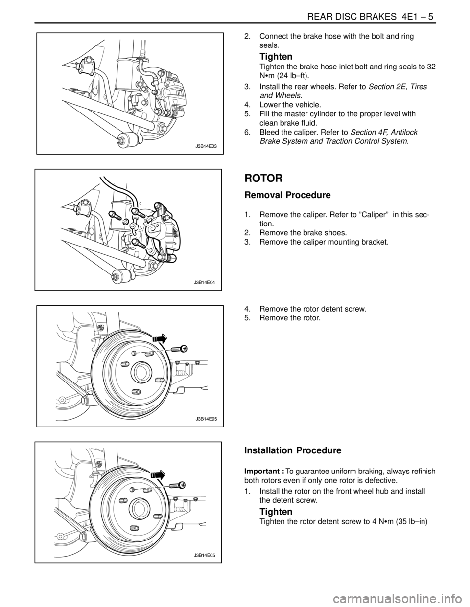
2. Connect the brake hose with the bolt and ring
seals.
Tighten
Tighten the brake hose inlet bolt and ring seals to 32
NSm (24 lb–ft).
3. Install the rear wheels. Refer to Section 2E, Tires
and Wheels.
4. Lower the vehicle.
5. Fill the master cylinder to the proper level with
clean brake fluid.
6. Bleed the caliper. Refer to Section 4F, Antilock
Brake System and Traction Control System.
ROTOR
Removal Procedure
1. Remove the caliper. Refer to ”Caliper” in this sec-
tion.
2. Remove the brake shoes.
3. Remove the caliper mounting bracket.
4. Remove the rotor detent screw.
5. Remove the rotor.
Installation Procedure
Important : To guarantee uniform braking, always refinish
both rotors even if only one rotor is defective.
1. Install the rotor on the front wheel hub and install
the detent screw.
Tighten
Tighten the rotor detent screw to 4 NSm (35 lb–in)
Page 1063 of 2643
4E1 – 6IREAR DISC BRAKES
DAEWOO V–121 BL4
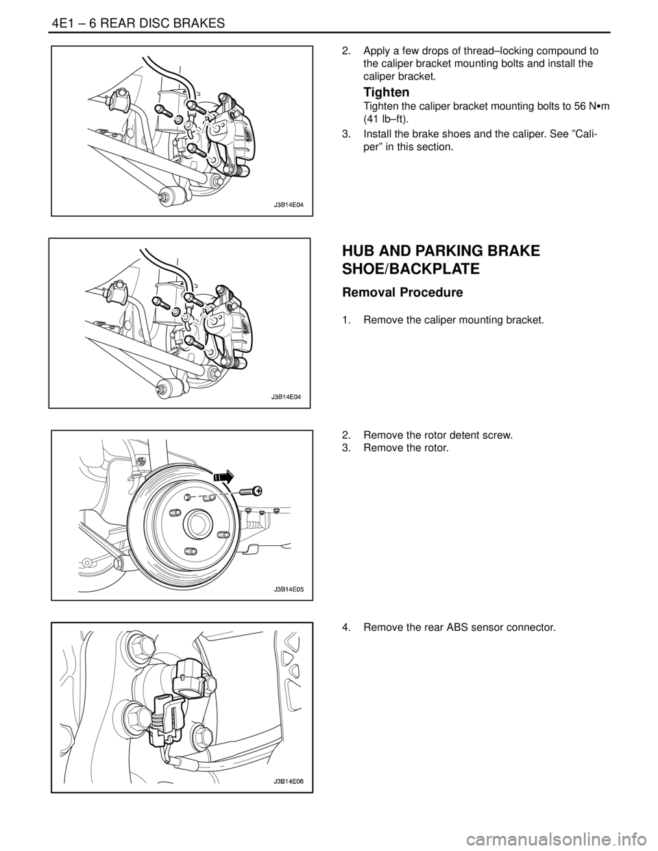
2. Apply a few drops of thread–locking compound to
the caliper bracket mounting bolts and install the
caliper bracket.
Tighten
Tighten the caliper bracket mounting bolts to 56 NSm
(41 lb–ft).
3. Install the brake shoes and the caliper. See ”Cali-
per” in this section.
HUB AND PARKING BRAKE
SHOE/BACKPLATE
Removal Procedure
1. Remove the caliper mounting bracket.
2. Remove the rotor detent screw.
3. Remove the rotor.
4. Remove the rear ABS sensor connector.
Page 1064 of 2643
REAR DISC BRAKES 4E1 – 7
DAEWOO V–121 BL4
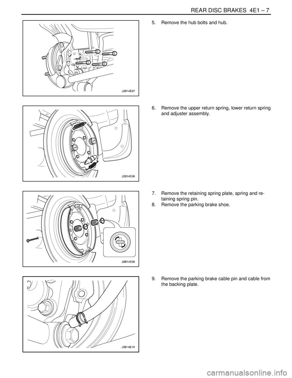
5. Remove the hub bolts and hub.
6. Remove the upper return spring, lower return spring
and adjuster assembly.
7. Remove the retaining spring plate, spring and re-
taining spring pin.
8. Remove the parking brake shoe.
9. Remove the parking brake cable pin and cable from
the backing plate.
Page 1065 of 2643
4E1 – 8IREAR DISC BRAKES
DAEWOO V–121 BL4
Installation Procedure
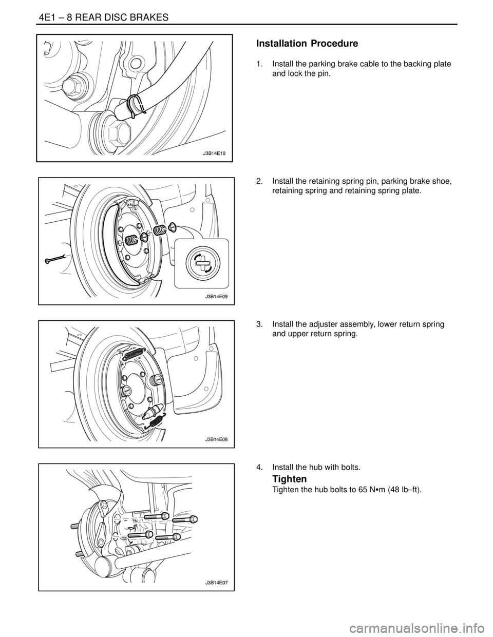
1. Install the parking brake cable to the backing plate
and lock the pin.
2. Install the retaining spring pin, parking brake shoe,
retaining spring and retaining spring plate.
3. Install the adjuster assembly, lower return spring
and upper return spring.
4. Install the hub with bolts.
Tighten
Tighten the hub bolts to 65 NSm (48 lb–ft).
Page 1066 of 2643
REAR DISC BRAKES 4E1 – 9
DAEWOO V–121 BL4
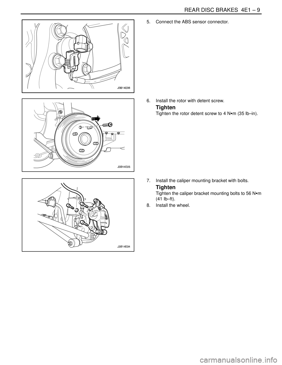
5. Connect the ABS sensor connector.
6. Install the rotor with detent screw.
Tighten
Tighten the rotor detent screw to 4 NSm (35 lb–in).
7. Install the caliper mounting bracket with bolts.
Tighten
Tighten the caliper bracket mounting bolts to 56 NSm
(41 lb–ft).
8. Install the wheel.
Page 1067 of 2643
4E1 – 10IREAR DISC BRAKES
DAEWOO V–121 BL4
UNIT REPAIR
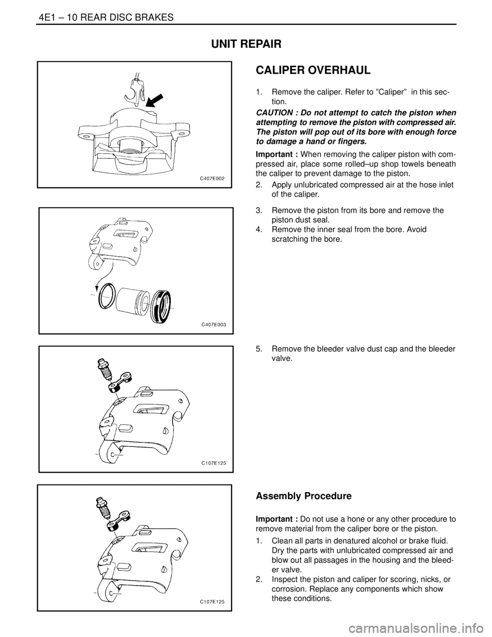
CALIPER OVERHAUL
1. Remove the caliper. Refer to ”Caliper” in this sec-
tion.
CAUTION : Do not attempt to catch the piston when
attempting to remove the piston with compressed air.
The piston will pop out of its bore with enough force
to damage a hand or fingers.
Important : When removing the caliper piston with com-
pressed air, place some rolled–up shop towels beneath
the caliper to prevent damage to the piston.
2. Apply unlubricated compressed air at the hose inlet
of the caliper.
3. Remove the piston from its bore and remove the
piston dust seal.
4. Remove the inner seal from the bore. Avoid
scratching the bore.
5. Remove the bleeder valve dust cap and the bleeder
valve.
Assembly Procedure
Important : Do not use a hone or any other procedure to
remove material from the caliper bore or the piston.
1. Clean all parts in denatured alcohol or brake fluid.
Dry the parts with unlubricated compressed air and
blow out all passages in the housing and the bleed-
er valve.
2. Inspect the piston and caliper for scoring, nicks, or
corrosion. Replace any components which show
these conditions.
Page 1068 of 2643
REAR DISC BRAKES 4E1 – 11
DAEWOO V–121 BL4
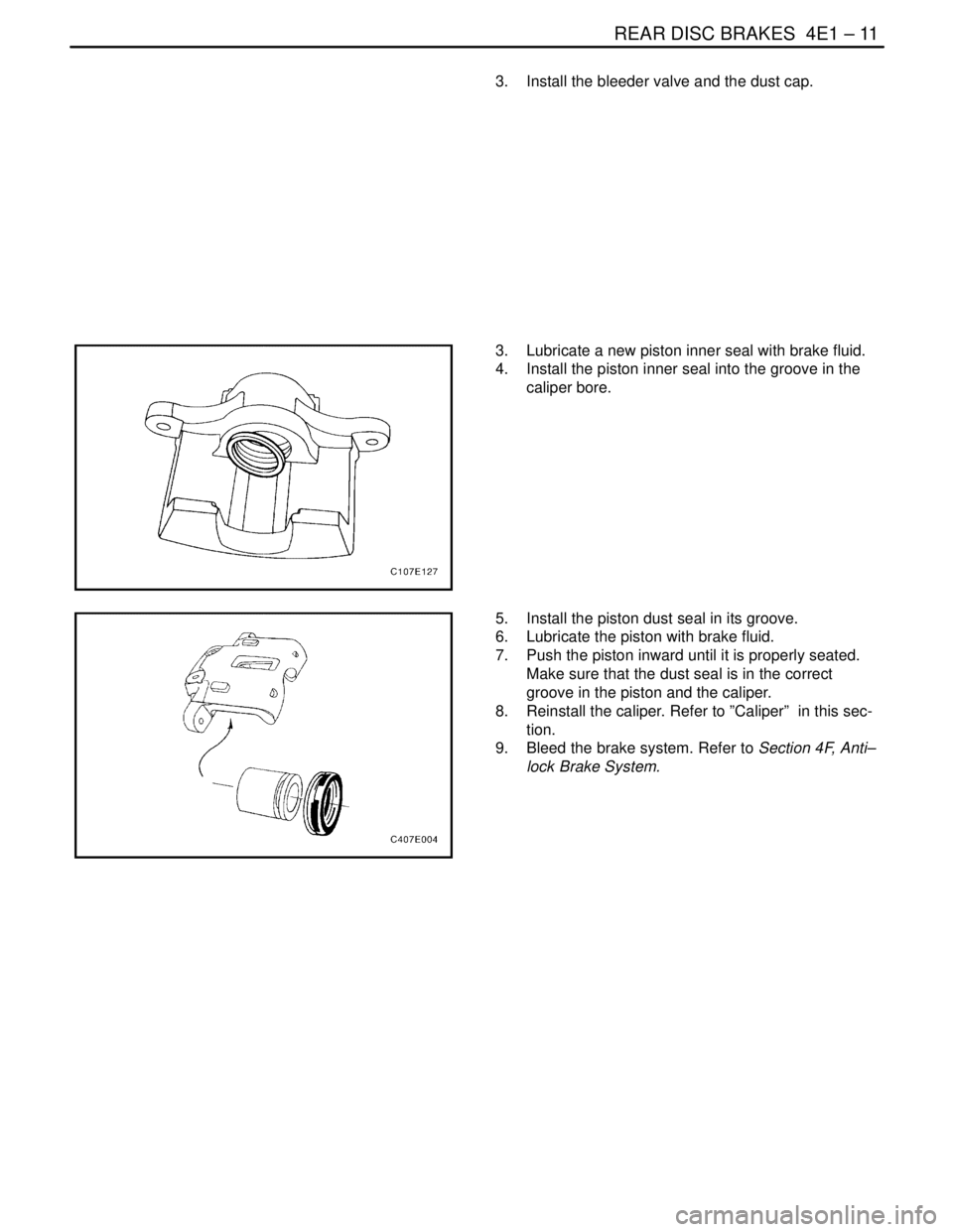
3. Install the bleeder valve and the dust cap.
3. Lubricate a new piston inner seal with brake fluid.
4. Install the piston inner seal into the groove in the
caliper bore.
5. Install the piston dust seal in its groove.
6. Lubricate the piston with brake fluid.
7. Push the piston inward until it is properly seated.
Make sure that the dust seal is in the correct
groove in the piston and the caliper.
8. Reinstall the caliper. Refer to ”Caliper” in this sec-
tion.
9. Bleed the brake system. Refer to Section 4F, Anti–
lock Brake System.
Page 1069 of 2643

4E1 – 12IREAR DISC BRAKES
DAEWOO V–121 BL4
GENERAL DESCRIPTION
AND SYSTEM OPERATION
DISC BRAKE CALIPER ASSEMBLY
The caliper has a single bore and is mounted to the steer-
ing knuckle with two mounting bolts. Hydraulic pressure,
created by applying the brake pedal, is converted by the
caliper to a stopping force. This force acts equally against
the piston and the bottom of the caliper bore to move the
piston outward and to slide the caliper inward, resulting in
a clamping action on the rotor. This clamping action forces
the linings against the rotor, creating friction to stop the ve-
hicle.S Replace all components included in the repair kits
used to service the caliper.
S Lubricate the rubber parts with clean brake fluid to
ease assembly.
S Do not use lubricated shop air on brake parts, as
damage to the rubber components may result.
S If any hydraulic component is removed or discon-
nected, it may be necessary to bleed all or part of
the brake system. Refer to Section 4F, Anti–lock
Brake System.
S Replace the shoes in axle sets only.
S The torque values specified are for dry, unlubri-
cated fasteners.
S Perform the service operations on a clean bench,
free from oily material.
Page 1070 of 2643

SECTION : 4E2
REAR DRUM BRAKES
TABLE OF CONTENTS
SPECIFICATIONS4E2–1 . . . . . . . . . . . . . . . . . . . . . . . . .
Fastener Tightening Specifications 4E2–1. . . . . . . . .
DIAGNOSIS4E2–1 . . . . . . . . . . . . . . . . . . . . . . . . . . . . . . .
Lining Inspection 4E2–1. . . . . . . . . . . . . . . . . . . . . . . . .
Drums 4E2–1. . . . . . . . . . . . . . . . . . . . . . . . . . . . . . . . . .
MAINTENANCE AND REPAIR4E2–3 . . . . . . . . . . . . . .
ON–VEHICLE SERVICE 4E2–3. . . . . . . . . . . . . . . . . . . .
Brake Adjustment 4E2–3. . . . . . . . . . . . . . . . . . . . . . . . Shoe and Lining 4E2–4. . . . . . . . . . . . . . . . . . . . . . . . .
Wheel Cylinder Assembly 4E2–7. . . . . . . . . . . . . . . . .
Backing Plate 4E2–8. . . . . . . . . . . . . . . . . . . . . . . . . . . .
UNIT REPAIR 4E2–10. . . . . . . . . . . . . . . . . . . . . . . . . . . .
Wheel Cylinder 4E2–10. . . . . . . . . . . . . . . . . . . . . . . . .
GENERAL DESCRIPTION AND SYSTEM
OPERATION4E2–12 . . . . . . . . . . . . . . . . . . . . . . . . . . . .
Drum Brakes 4E2–12. . . . . . . . . . . . . . . . . . . . . . . . . . .
SPECIFICATIONS
FASTENER TIGHTENING SPECIFICATIONS
ApplicationNSmLb–FtLb–In
Brake Line1612–
Brake Wheel Hub/Backing Plate–to–Rear
Axle Nuts2821–
Wheel Cylinder–to–Backing Plate Bolt8–71
DIAGNOSIS
LINING INSPECTION
1. Raise and suitably support the vehicle.
2. Remove the wheel. Refer to Section 2E, Tires and
Wheels.
3. Release the parking brake.
4. Remove the drum. Refer to ” Drum” in this section.
5. Measure the lining thickness. The minimum lining
thickness is 0.5 mm (0.02 inch).
CAUTION : To avoid injury when servicing brake
parts, do not create dust by grinding or sanding the
brake linings or by cleaning the wheel brake parts
with a dry brush or with compressed air.
Important : Replace the shoe and lining assembly in axle
sets only.
6. Install the drum, if removed. Refer to ”One–Piece
Drum” or ”Two–Piece Drum” in this section.
7. Install the wheel, if removed. Refer to Section 2E,
Tires and Wheels.
8. Lower the vehicle.
DRUMS
Whenever brake drums are removed, they should be thor-
oughly cleaned and inspected to see if the drums are
cracked, scored, deeply grooved, or beyond the specified
out–of–round limit.
S A cracked drum is unsafe for further service and-
must be replaced. Do not attempt to weld a cracked
drum. Smooth out any slight scores.
S Heavy or extensive scoring will cause excessive
brake lining wear and may require refinishing the
drum braking surface.
S If the brake linings are slightly worn but are still re-
usable and the drum is grooved, polish the drum
with a fine emery cloth but do not refinish it. Elimi-
nating all grooves in the drum and smoothing the
ridges on the lining would remove too much metal
and lining. If left alone, the grooves and ridges
match, and satisfactory service can be obtained. If
the brake linings need to be replaced, refinish a
grooved drum. A grooved drum, used with a new