DAEWOO NUBIRA 2004 Service Repair Manual
NUBIRA 2004
DAEWOO
DAEWOO
https://www.carmanualsonline.info/img/54/56879/w960_56879-0.png
DAEWOO NUBIRA 2004 Service Repair Manual
Trending: ad blue, main idle throttle actuator valve, Break oil, ESP, adding oil, wiring diagram, fuse diagram
Page 1701 of 2643
AISIN AUTOMATIC TRANSAXLE 5A2 – 111
DAEWOO V–121 BL4
Installation Procedure
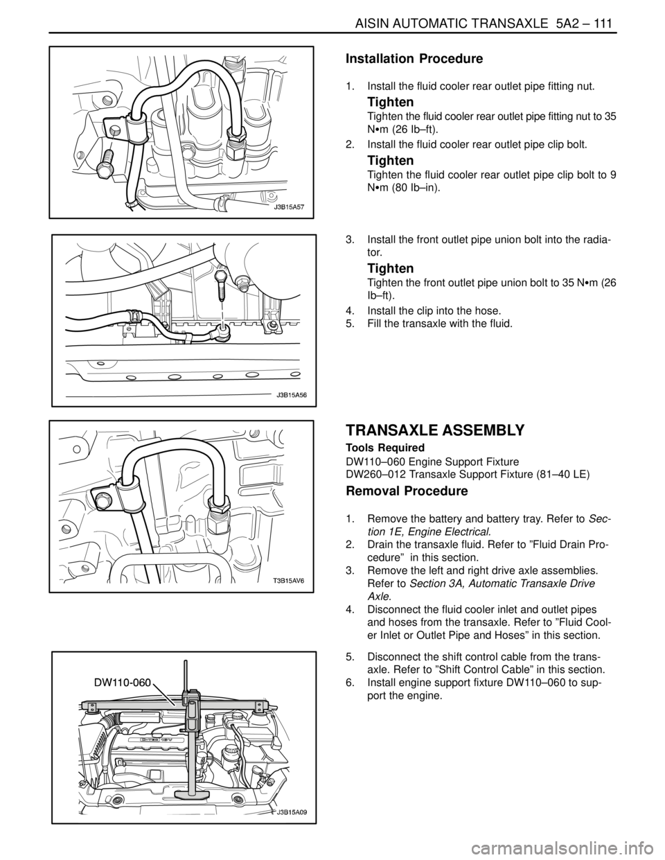
1. Install the fluid cooler rear outlet pipe fitting nut.
Tighten
Tighten the fluid cooler rear outlet pipe fitting nut to 35
NSm (26 Ib–ft).
2. Install the fluid cooler rear outlet pipe clip bolt.
Tighten
Tighten the fluid cooler rear outlet pipe clip bolt to 9
NSm (80 Ib–in).
3. Install the front outlet pipe union bolt into the radia-
tor.
Tighten
Tighten the front outlet pipe union bolt to 35 NSm (26
Ib–ft).
4. Install the clip into the hose.
5. Fill the transaxle with the fluid.
TRANSAXLE ASSEMBLY
Tools Required
DW110–060 Engine Support Fixture
DW260–012 Transaxle Support Fixture (81–40 LE)
Removal Procedure
1. Remove the battery and battery tray. Refer to Sec-
tion 1E, Engine Electrical.
2. Drain the transaxle fluid. Refer to ”Fluid Drain Pro-
cedure” in this section.
3. Remove the left and right drive axle assemblies.
Refer to Section 3A, Automatic Transaxle Drive
Axle.
4. Disconnect the fluid cooler inlet and outlet pipes
and hoses from the transaxle. Refer to ”Fluid Cool-
er Inlet or Outlet Pipe and Hoses” in this section.
5. Disconnect the shift control cable from the trans-
axle. Refer to ”Shift Control Cable” in this section.
6. Install engine support fixture DW110–060 to sup-
port the engine.
Page 1702 of 2643
5A2 – 112IAISIN AUTOMATIC TRANSAXLE
DAEWOO V–121 BL4
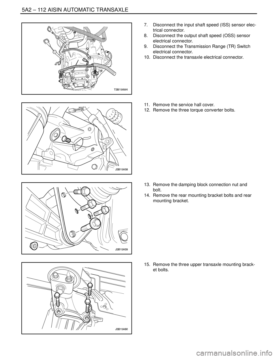
7. Disconnect the input shaft speed (ISS) sensor elec-
trical connector.
8. Disconnect the output shaft speed (OSS) sensor
electrical connector.
9. Disconnect the Transmission Range (TR) Switch
electrical connector.
10. Disconnect the transaxle electrical connector.
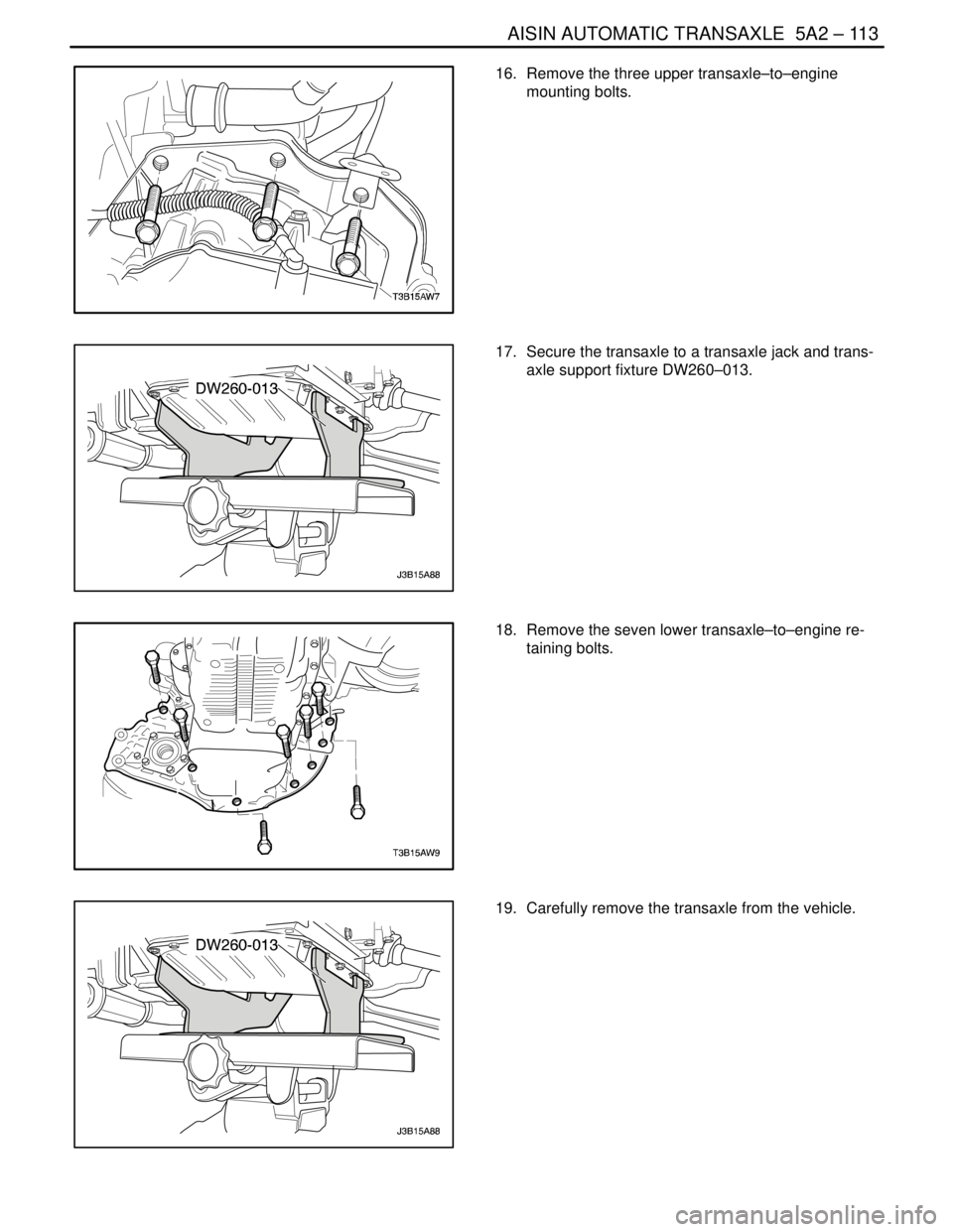
11. Remove the service hall cover.
12. Remove the three torque converter bolts.
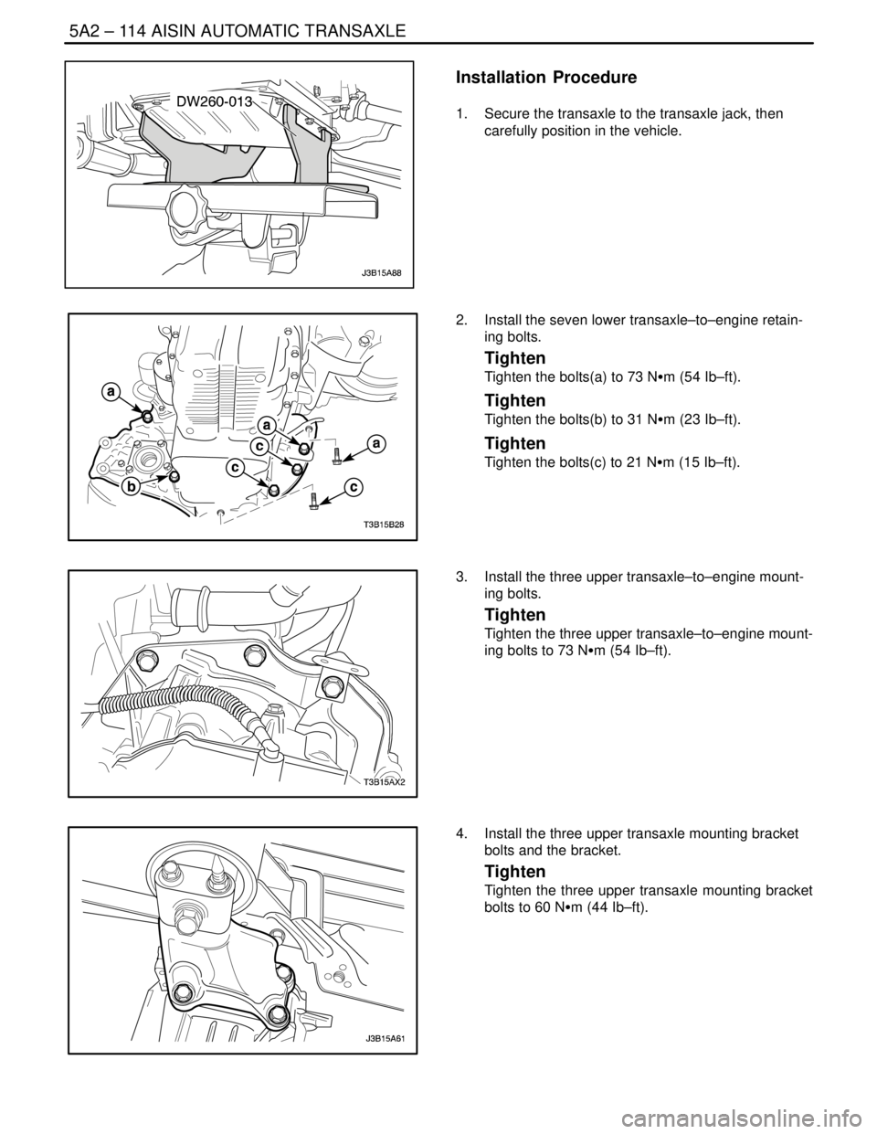
13. Remove the damping block connection nut and
bolt.
14. Remove the rear mounting bracket bolts and rear
mounting bracket.
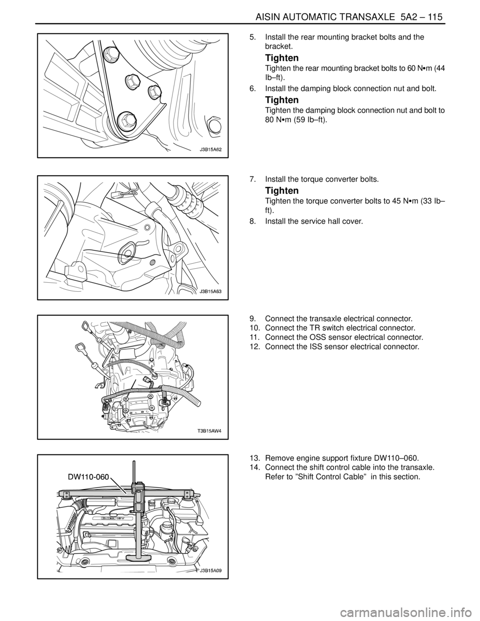
15. Remove the three upper transaxle mounting brack-
et bolts.
Page 1703 of 2643
AISIN AUTOMATIC TRANSAXLE 5A2 – 113
DAEWOO V–121 BL4
16. Remove the three upper transaxle–to–engine
mounting bolts.
17. Secure the transaxle to a transaxle jack and trans-
axle support fixture DW260–013.
18. Remove the seven lower transaxle–to–engine re-
taining bolts.
19. Carefully remove the transaxle from the vehicle.
Page 1704 of 2643
5A2 – 114IAISIN AUTOMATIC TRANSAXLE
DAEWOO V–121 BL4
Installation Procedure
1. Secure the transaxle to the transaxle jack, then
carefully position in the vehicle.
2. Install the seven lower transaxle–to–engine retain-
ing bolts.
Tighten
Tighten the bolts(a) to 73 NSm (54 Ib–ft).
Tighten
Tighten the bolts(b) to 31 NSm (23 Ib–ft).
Tighten
Tighten the bolts(c) to 21 NSm (15 Ib–ft).
3. Install the three upper transaxle–to–engine mount-
ing bolts.
Tighten
Tighten the three upper transaxle–to–engine mount-
ing bolts to 73 NSm (54 Ib–ft).
4. Install the three upper transaxle mounting bracket
bolts and the bracket.
Tighten
Tighten the three upper transaxle mounting bracket
bolts to 60 NSm (44 Ib–ft).
Page 1705 of 2643
AISIN AUTOMATIC TRANSAXLE 5A2 – 115
DAEWOO V–121 BL4
5. Install the rear mounting bracket bolts and the
bracket.
Tighten
Tighten the rear mounting bracket bolts to 60 NSm (44
Ib–ft).
6. Install the damping block connection nut and bolt.
Tighten
Tighten the damping block connection nut and bolt to
80 NSm (59 Ib–ft).
7. Install the torque converter bolts.
Tighten
Tighten the torque converter bolts to 45 NSm (33 Ib–
ft).
8. Install the service hall cover.
9. Connect the transaxle electrical connector.
10. Connect the TR switch electrical connector.
11. Connect the OSS sensor electrical connector.
12. Connect the ISS sensor electrical connector.
13. Remove engine support fixture DW110–060.
14. Connect the shift control cable into the transaxle.
Refer to ”Shift Control Cable” in this section.
Page 1706 of 2643
5A2 – 116IAISIN AUTOMATIC TRANSAXLE
DAEWOO V–121 BL4
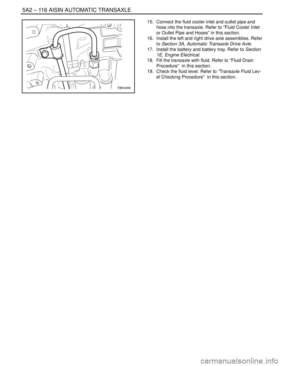
15. Connect the fluid cooler inlet and outlet pipe and
hose into the transaxle. Refer to ”Fluid Cooler Inlet
or Outlet Pipe and Hoses” in this section.
16. Install the left and right drive axle assemblies. Refer
to Section 3A, Automatic Transaxle Drive Axle.
17. Install the battery and battery tray. Refer to Section
1E, Engine Electrical.
18. Fill the transaxle with fluid. Refer to ”Fluid Drain
Procedure” in this section.
19. Check the fluid level. Refer to ”Transaxle Fluid Lev-
el Checking Procedure” in this section.
Page 1707 of 2643
AISIN AUTOMATIC TRANSAXLE 5A2 – 117
DAEWOO V–121 BL4
UNIT REPAIR
MAJOR COMPONENT DISASSEMBLY
Tools Required
DW240–020 Brake/Clutch Spring Compressor
DW240–050 Overdrive Brake Adapter
DW240–060–01 Brake Spring Compressor Bolt/Nut
DW240–070 1st & Reverse Brake Adapter
DW240–080 2nd Brake Adapter
DW240–090 Planetary Ring Gear Remover
DW240–150 Transaxle Case Side Bearing Outer Race
Adapter
DW240–170 Adapter Handle
DW260–021–02 Automatic Transaxle Overhaul Fixture
(81–40 LE)
DW260–041 Planetary Ring Gear Nut Removal/Installa-
tion Socket
Disassembly Procedure
1. Remove the transaxle assembly from the vehicle.
Refer to”Transaxle Assembly” in this section.
2. Install the transaxle assembly to the transaxle sup-
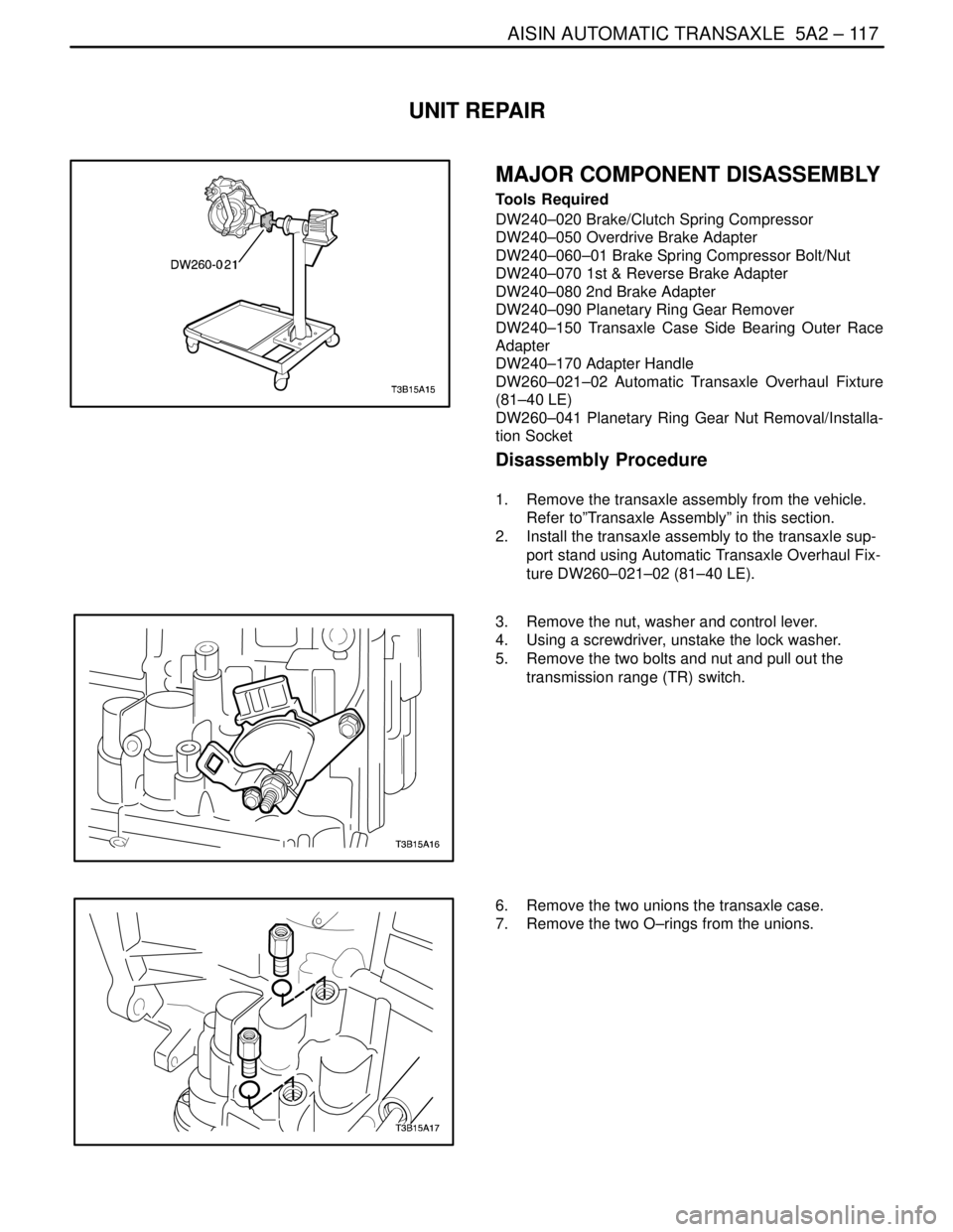
port stand using Automatic Transaxle Overhaul Fix-
ture DW260–021–02 (81–40 LE).
3. Remove the nut, washer and control lever.
4. Using a screwdriver, unstake the lock washer.
5. Remove the two bolts and nut and pull out the
transmission range (TR) switch.
6. Remove the two unions the transaxle case.
7. Remove the two O–rings from the unions.
Page 1708 of 2643
5A2 – 118IAISIN AUTOMATIC TRANSAXLE
DAEWOO V–121 BL4
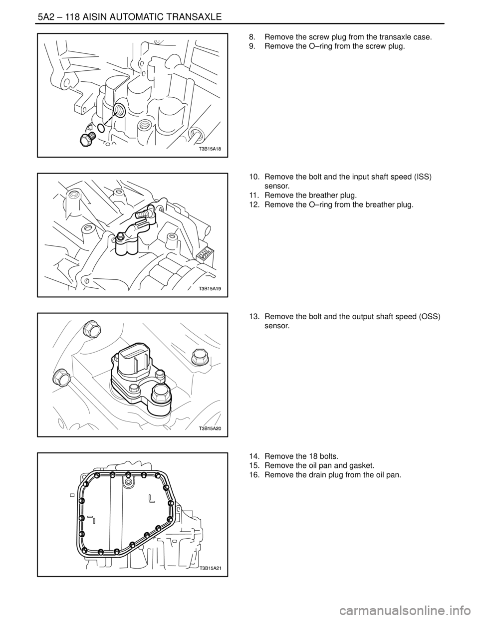
8. Remove the screw plug from the transaxle case.
9. Remove the O–ring from the screw plug.
10. Remove the bolt and the input shaft speed (ISS)
sensor.
11. Remove the breather plug.
12. Remove the O–ring from the breather plug.
13. Remove the bolt and the output shaft speed (OSS)
sensor.
14. Remove the 18 bolts.
15. Remove the oil pan and gasket.
16. Remove the drain plug from the oil pan.
Page 1709 of 2643
AISIN AUTOMATIC TRANSAXLE 5A2 – 119
DAEWOO V–121 BL4
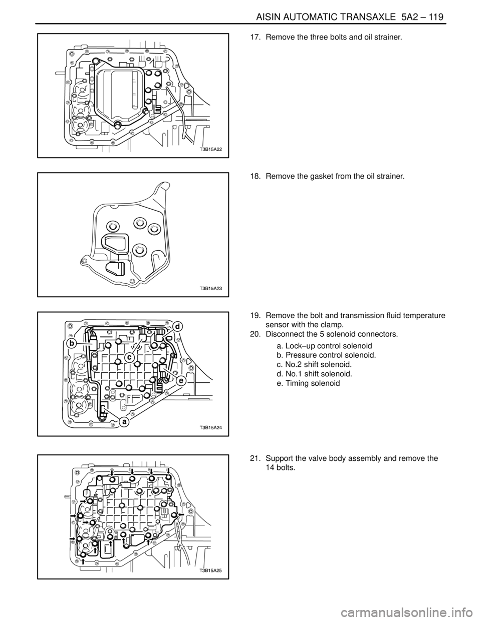
17. Remove the three bolts and oil strainer.
18. Remove the gasket from the oil strainer.
19. Remove the bolt and transmission fluid temperature
sensor with the clamp.
20. Disconnect the 5 solenoid connectors.
a. Lock–up control solenoid
b. Pressure control solenoid.
c. No.2 shift solenoid.
d. No.1 shift solenoid.
e. Timing solenoid
21. Support the valve body assembly and remove the
14 bolts.
Page 1710 of 2643
5A2 – 120IAISIN AUTOMATIC TRANSAXLE
DAEWOO V–121 BL4
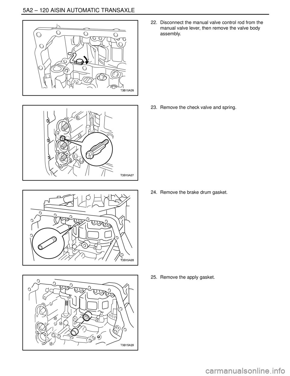
22. Disconnect the manual valve control rod from the
manual valve lever, then remove the valve body
assembly.
23. Remove the check valve and spring.
24. Remove the brake drum gasket.
25. Remove the apply gasket.
Trending: spare tire, run flat, driver seat adjustment, mileage, MITA, coolant, high beam

