DAEWOO NUBIRA 2004 Service Repair Manual
NUBIRA 2004
DAEWOO
DAEWOO
https://www.carmanualsonline.info/img/54/56879/w960_56879-0.png
DAEWOO NUBIRA 2004 Service Repair Manual
Trending: door lock, spare tire, section 7, oil change, engine overheat, main idle throttle actuator valve, Break
Page 1711 of 2643
AISIN AUTOMATIC TRANSAXLE 5A2 – 121
DAEWOO V–121 BL4
WARNING : USE CAUTION WHEN REMOVING COM-
PONENTS WITH COMPRESSED AIR OR PERSONAL
INJURY MAY RESULT.
Notice : Blowing off the air may cause the piston’s jump–
out. When removing the piston, hold it with your hand us-
ing a waste cloth.
Notice : Take care not to splash automatic transaxle fluid
(ATF) when air–blowing.
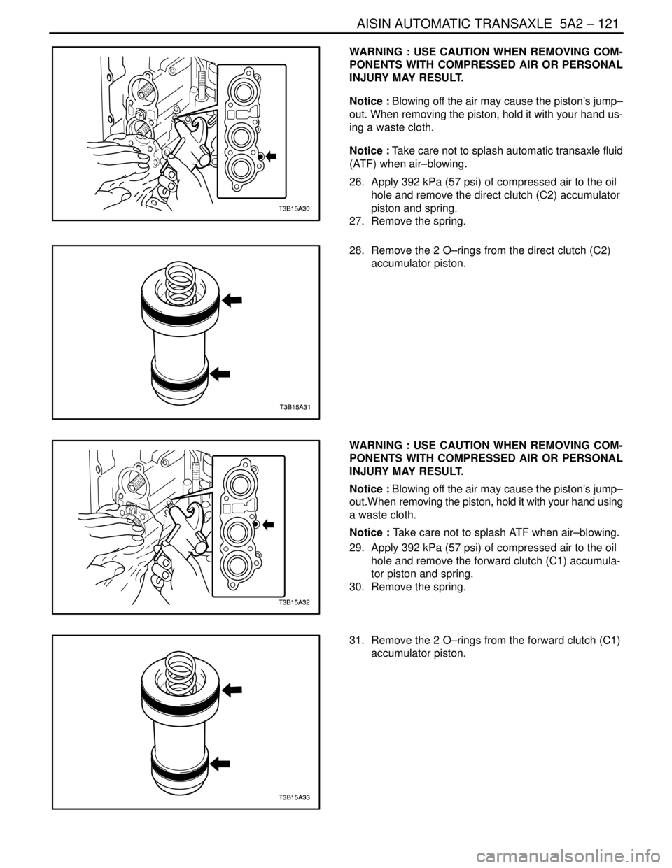
26. Apply 392 kPa (57 psi) of compressed air to the oil
hole and remove the direct clutch (C2) accumulator
piston and spring.
27. Remove the spring.
28. Remove the 2 O–rings from the direct clutch (C2)
accumulator piston.
WARNING : USE CAUTION WHEN REMOVING COM-
PONENTS WITH COMPRESSED AIR OR PERSONAL
INJURY MAY RESULT.
Notice : Blowing off the air may cause the piston’s jump–
out.When removing the piston, hold it with your hand using
a waste cloth.
Notice : Take care not to splash ATF when air–blowing.
29. Apply 392 kPa (57 psi) of compressed air to the oil
hole and remove the forward clutch (C1) accumula-
tor piston and spring.
30. Remove the spring.
31. Remove the 2 O–rings from the forward clutch (C1)
accumulator piston.
Page 1712 of 2643
5A2 – 122IAISIN AUTOMATIC TRANSAXLE
DAEWOO V–121 BL4
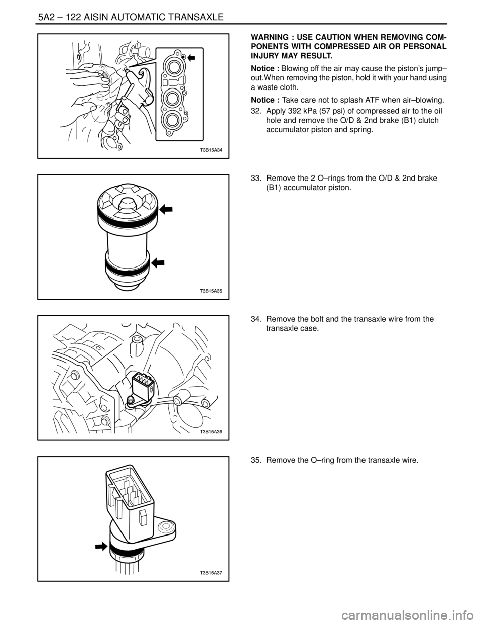
WARNING : USE CAUTION WHEN REMOVING COM-
PONENTS WITH COMPRESSED AIR OR PERSONAL
INJURY MAY RESULT.
Notice : Blowing off the air may cause the piston’s jump–
out.When removing the piston, hold it with your hand using
a waste cloth.
Notice : Take care not to splash ATF when air–blowing.
32. Apply 392 kPa (57 psi) of compressed air to the oil
hole and remove the O/D & 2nd brake (B1) clutch
accumulator piston and spring.
33. Remove the 2 O–rings from the O/D & 2nd brake
(B1) accumulator piston.
34. Remove the bolt and the transaxle wire from the
transaxle case.
35. Remove the O–ring from the transaxle wire.
Page 1713 of 2643
AISIN AUTOMATIC TRANSAXLE 5A2 – 123
DAEWOO V–121 BL4
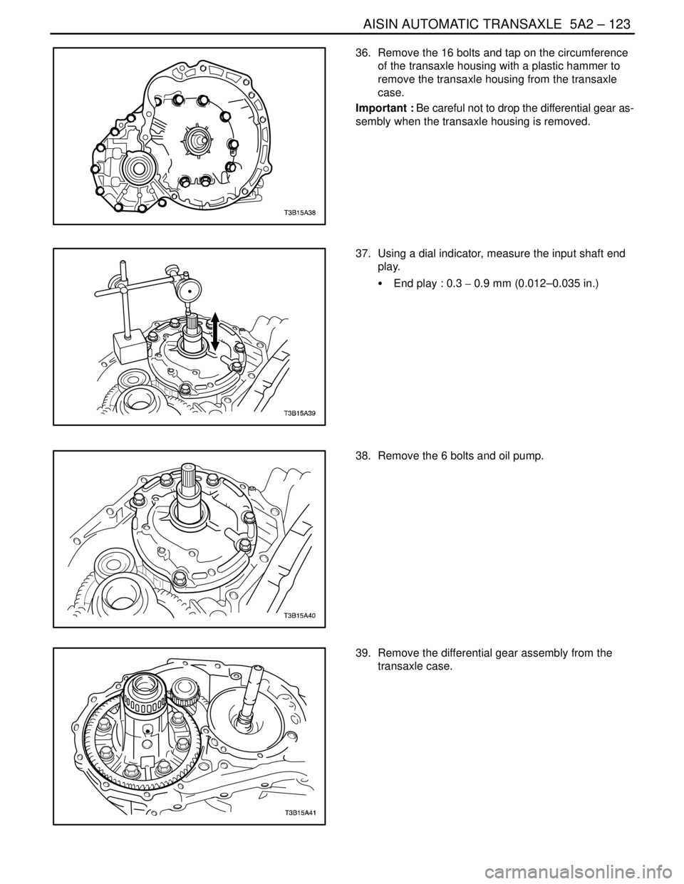
36. Remove the 16 bolts and tap on the circumference
of the transaxle housing with a plastic hammer to
remove the transaxle housing from the transaxle
case.
Important : Be careful not to drop the differential gear as-
sembly when the transaxle housing is removed.
37. Using a dial indicator, measure the input shaft end
play.
S End play : 0.3 � 0.9 mm (0.012–0.035 in.)
38. Remove the 6 bolts and oil pump.
39. Remove the differential gear assembly from the
transaxle case.
Page 1714 of 2643
5A2 – 124IAISIN AUTOMATIC TRANSAXLE
DAEWOO V–121 BL4
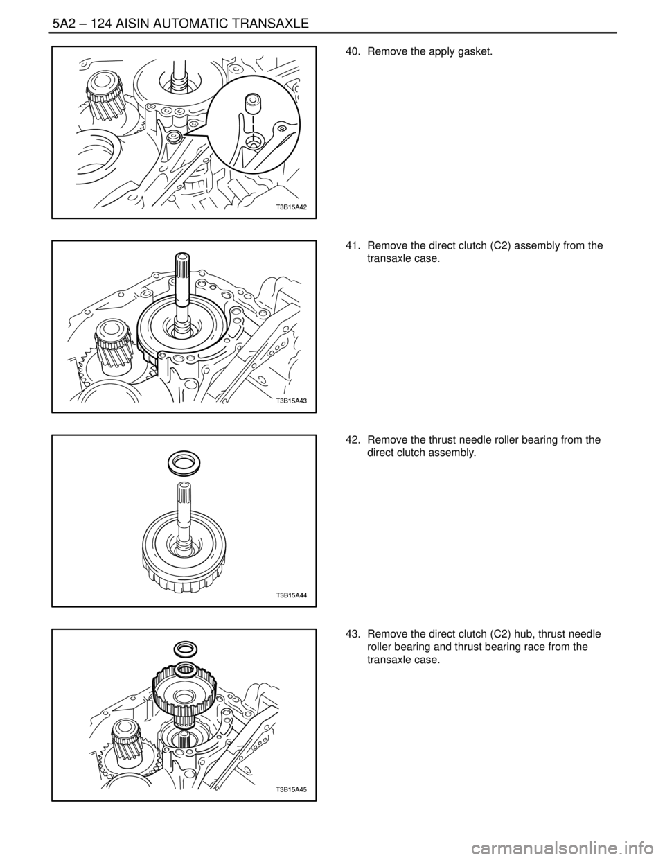
40. Remove the apply gasket.
41. Remove the direct clutch (C2) assembly from the
transaxle case.
42. Remove the thrust needle roller bearing from the
direct clutch assembly.
43. Remove the direct clutch (C2) hub, thrust needle
roller bearing and thrust bearing race from the
transaxle case.
Page 1715 of 2643
AISIN AUTOMATIC TRANSAXLE 5A2 – 125
DAEWOO V–121 BL4
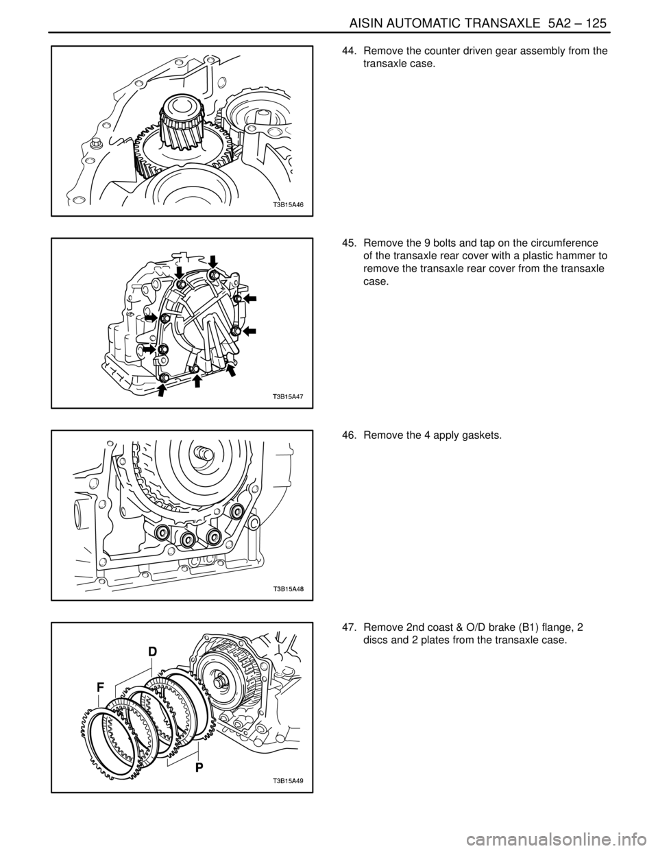
44. Remove the counter driven gear assembly from the
transaxle case.
45. Remove the 9 bolts and tap on the circumference
of the transaxle rear cover with a plastic hammer to
remove the transaxle rear cover from the transaxle
case.
46. Remove the 4 apply gaskets.
47. Remove 2nd coast & O/D brake (B1) flange, 2
discs and 2 plates from the transaxle case.
Page 1716 of 2643
5A2 – 126IAISIN AUTOMATIC TRANSAXLE
DAEWOO V–121 BL4
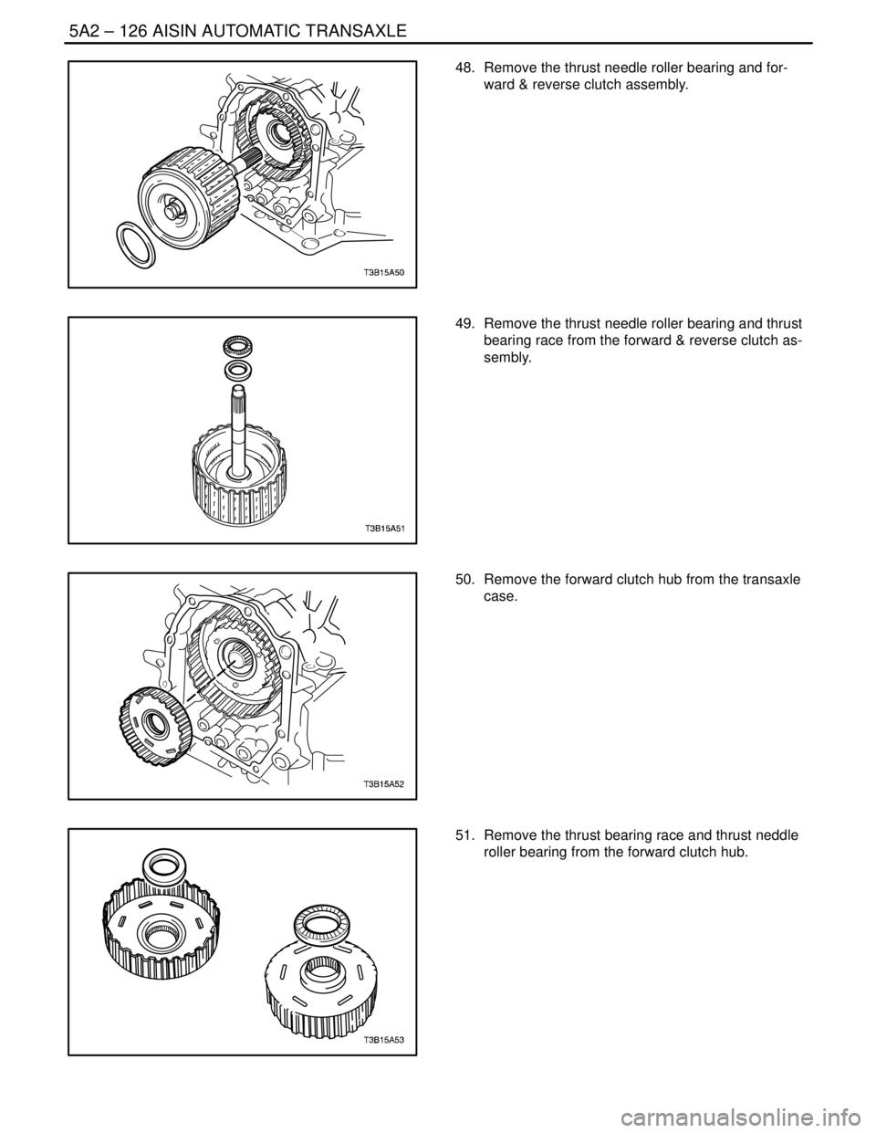
48. Remove the thrust needle roller bearing and for-
ward & reverse clutch assembly.
49. Remove the thrust needle roller bearing and thrust
bearing race from the forward & reverse clutch as-
sembly.
50. Remove the forward clutch hub from the transaxle
case.
51. Remove the thrust bearing race and thrust neddle
roller bearing from the forward clutch hub.
Page 1717 of 2643
AISIN AUTOMATIC TRANSAXLE 5A2 – 127
DAEWOO V–121 BL4
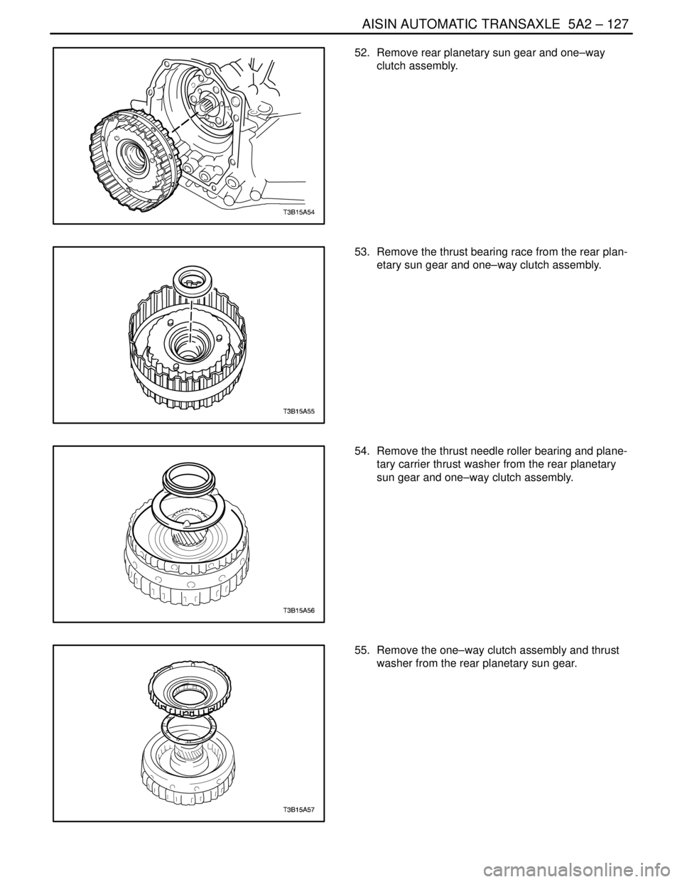
52. Remove rear planetary sun gear and one–way
clutch assembly.
53. Remove the thrust bearing race from the rear plan-
etary sun gear and one–way clutch assembly.
54. Remove the thrust needle roller bearing and plane-
tary carrier thrust washer from the rear planetary
sun gear and one–way clutch assembly.
55. Remove the one–way clutch assembly and thrust
washer from the rear planetary sun gear.
Page 1718 of 2643
5A2 – 128IAISIN AUTOMATIC TRANSAXLE
DAEWOO V–121 BL4
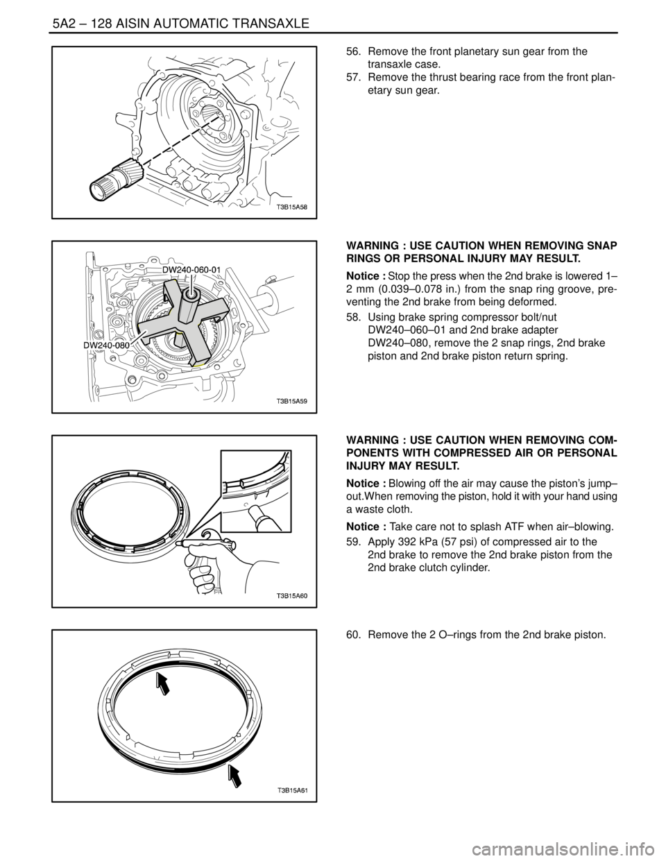
56. Remove the front planetary sun gear from the
transaxle case.
57. Remove the thrust bearing race from the front plan-
etary sun gear.
WARNING : USE CAUTION WHEN REMOVING SNAP
RINGS OR PERSONAL INJURY MAY RESULT.
Notice : Stop the press when the 2nd brake is lowered 1–
2 mm (0.039–0.078 in.) from the snap ring groove, pre-
venting the 2nd brake from being deformed.
58. Using brake spring compressor bolt/nut
DW240–060–01 and 2nd brake adapter
DW240–080, remove the 2 snap rings, 2nd brake
piston and 2nd brake piston return spring.
WARNING : USE CAUTION WHEN REMOVING COM-
PONENTS WITH COMPRESSED AIR OR PERSONAL
INJURY MAY RESULT.
Notice : Blowing off the air may cause the piston’s jump–
out.When removing the piston, hold it with your hand using
a waste cloth.
Notice : Take care not to splash ATF when air–blowing.
59. Apply 392 kPa (57 psi) of compressed air to the
2nd brake to remove the 2nd brake piston from the
2nd brake clutch cylinder.
60. Remove the 2 O–rings from the 2nd brake piston.
Page 1719 of 2643
AISIN AUTOMATIC TRANSAXLE 5A2 – 129
DAEWOO V–121 BL4
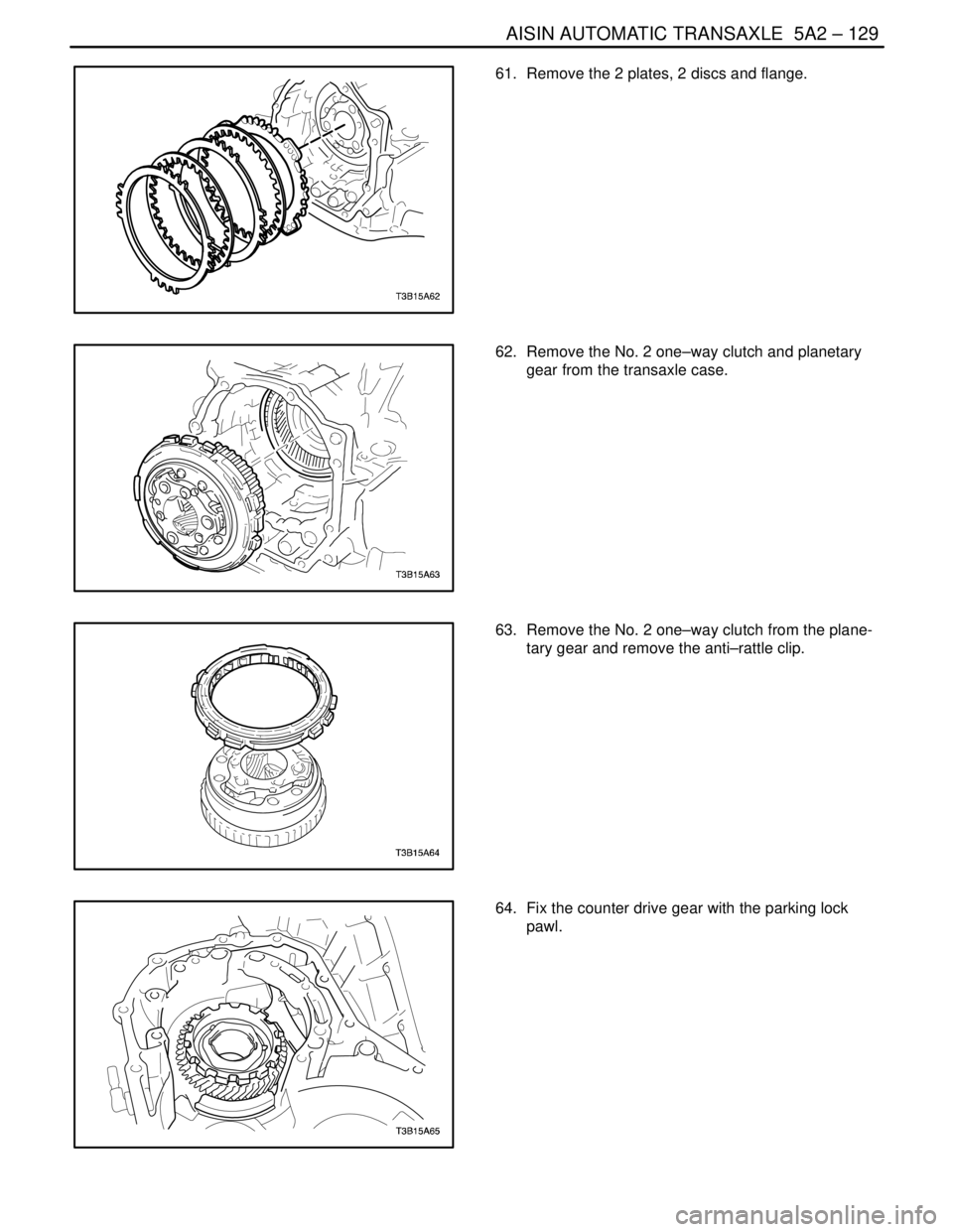
61. Remove the 2 plates, 2 discs and flange.
62. Remove the No. 2 one–way clutch and planetary
gear from the transaxle case.
63. Remove the No. 2 one–way clutch from the plane-
tary gear and remove the anti–rattle clip.
64. Fix the counter drive gear with the parking lock
pawl.
Page 1720 of 2643
5A2 – 130IAISIN AUTOMATIC TRANSAXLE
DAEWOO V–121 BL4
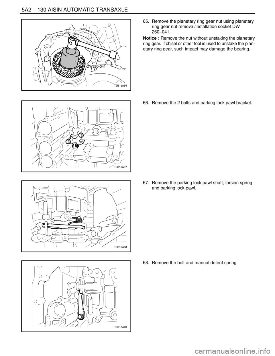
65. Remove the planetary ring gear nut using planetary
ring gear nut removal/installation socket DW
260–041.
Notice : Remove the nut without unstaking the planetary
ring gear. If chisel or other tool is used to unstake the plan-
etary ring gear, such impact may damage the bearing.
66. Remove the 2 bolts and parking lock pawl bracket.
67. Remove the parking lock pawl shaft, torsion spring
and parking lock pawl.
68. Remove the bolt and manual detent spring.
Trending: Break, safety belt, jump start terminals, window, service interval, high idle speed, technical data

