fuel filter DATSUN 210 1979 User Guide
[x] Cancel search | Manufacturer: DATSUN, Model Year: 1979, Model line: 210, Model: DATSUN 210 1979Pages: 548, PDF Size: 28.66 MB
Page 35 of 548
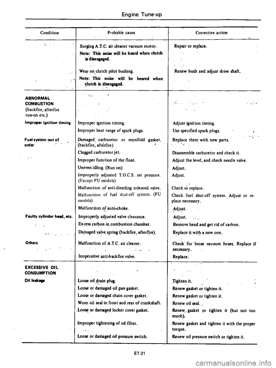
Condition
ABNORMAL
COMBUSTION
backfire
afterfire
run
on
etc
Improper
ignition
timing
Fuel
system
out
of
order
Feulty
cylinder
heed
etc
Others
EXCESSIVE
OIL
CONSUMPTION
Oilleek8111
Engine
Tune
up
Probable
cause
Surging
A
T
C
air
cleaner
vacuum
motor
Note
This
noise
will
be
hmnl
when
clutch
iI
disengaged
We
r
on
clutch
pilot
bushing
Not
e
This
noise
will
be
heared
when
utch
iI
disengaged
Improper
ignition
timing
Improper
heal
range
of
spark
plugs
Damaged
carburetor
or
manifold
gasket
backfire
aftedire
Clogged
carburetor
jet
Improper
function
of
the
float
Uneven
idling
Run
on
Improperly
adjusted
T
O
C
S
set
pressure
Except
FU
models
Malfunction
of
anti
dieseling
solenoid
valve
Malfunction
of
fuel
shut
off
system
FU
models
Malfunction
or
auto
hoke
Improper
y
adjusted
valve
clearance
Excess
carbon
in
combustion
chamber
Da
laged
alve
spring
backfire
after
he
Malfunction
of
A
T
C
air
cleaner
Inoperative
anti4lackfire
valve
Loose
oil
tain
plUI
ose
or
damaged
oil
pan
gasket
Loose
or
damaled
chain
cover
gasket
Wom
oil
seal
in
front
and
rear
of
crankshaft
Loo
or
damaged
locker
cover
gasket
Improper
lilhtening
of
oU
filter
Loose
or
damaled
oil
pressure
switch
ET
21
Corrective
action
Repair
or
replace
Renew
bush
and
adjust
drive
shaft
Adjust
ignition
liming
Use
specified
spark
plugs
Replace
them
with
new
parts
Disassemble
carburetor
and
check
it
Adjust
the
level
and
check
needle
valve
Adjust
Adjust
Check
or
replace
Check
fuel
shut
off
system
Adjust
or
re
place
necessary
Adjust
Adjust
Remove
head
and
get
rid
of
carbon
Replace
it
wit
a
new
one
Check
for
loose
vacuum
hoses
Replace
if
necessary
Replace
Tighten
it
Renew
lasket
or
tighten
iI
Renew
gasket
or
lighten
it
Renew
oil
seal
Renew
gasket
r
lighten
it
but
not
too
much
Renew
gasket
and
tighten
it
with
the
proper
torque
Renew
oil
pressure
switch
or
tighten
it
Page 36 of 548
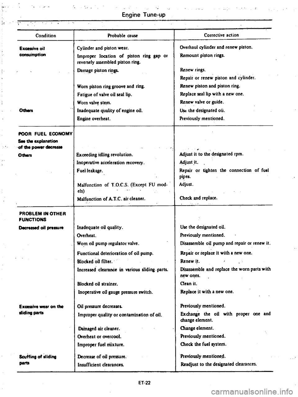
Condition
Ex
iv
oil
consumption
Odlen
POOR
FUEL
ECONOMY
See
the
explanation
oI
thtI
power
cIec
01hen
PROBLEM
IN
OTHER
FUNCTIONS
t
1
oil
pre
E
eronthe
lIiding
par1J
Scuffing
oIlliding
par1J
Engine
Tune
up
Probable
cause
Cylinder
and
piston
wear
Improper
lOcation
of
pi5ton
ring
gap
or
reversely
assembled
piston
ring
Damage
pi5ton
r
gs
Wom
pilton
ring
groove
and
ring
Fatigue
of
valve
oil
seal
lip
Worn
valv
stem
Inadequate
qUality
of
engine
oil
Engine
overheat
Exceeding
idling
revolution
Inoperative
acceleration
covel
Fuelleakage
Malfunction
of
T
O
C
S
Except
FU
mod
els
Malfunction
of
A
T
C
air
cleaner
Inadequate
oil
quality
Overheat
Worn
oil
pump
regulator
valve
Functional
deterioration
of
oil
pump
Blocked
oil
filter
Increased
clearanCe
in
various
sliding
parts
Blocked
oil
strainer
Inoperative
oil
gauge
pressure
switch
Oil
pressure
decreases
Improper
quality
or
contamination
of
oil
Damaged
air
cleaner
Overheat
or
overcool
Improper
fuel
nUxture
Decrease
of
oil
presSure
Insufficient
clearances
ET
22
Corrective
action
Overhaul
cylinder
and
renew
piston
Remount
piston
rings
Renew
rings
Repair
or
renew
piston
and
cylinder
Renew
piston
and
piston
ring
Replace
seal
lip
with
a
new
one
Renew
valve
or
guide
Us
the
designated
ou
Previously
mentioned
Adjust
it
to
the
designated
rpm
Adjust
it
Repair
or
lighten
the
connection
of
fuel
pipes
Adjust
Check
and
replace
Use
the
designated
oil
Previously
mentioned
Disassemble
oil
pump
and
repair
or
renew
it
Ref4ir
or
replace
it
with
I
new
one
Renew
i
t
Disassemble
and
replace
the
worn
parts
with
n
w
of
es
Clean
it
Replace
it
with
a
new
one
Previously
mentioned
Exchange
the
oil
with
proper
one
and
change
element
Otange
element
Previously
mentioned
Oteck
the
fuel
system
Previously
mentione
d
Readjust
to
the
designated
clearances
Page 37 of 548
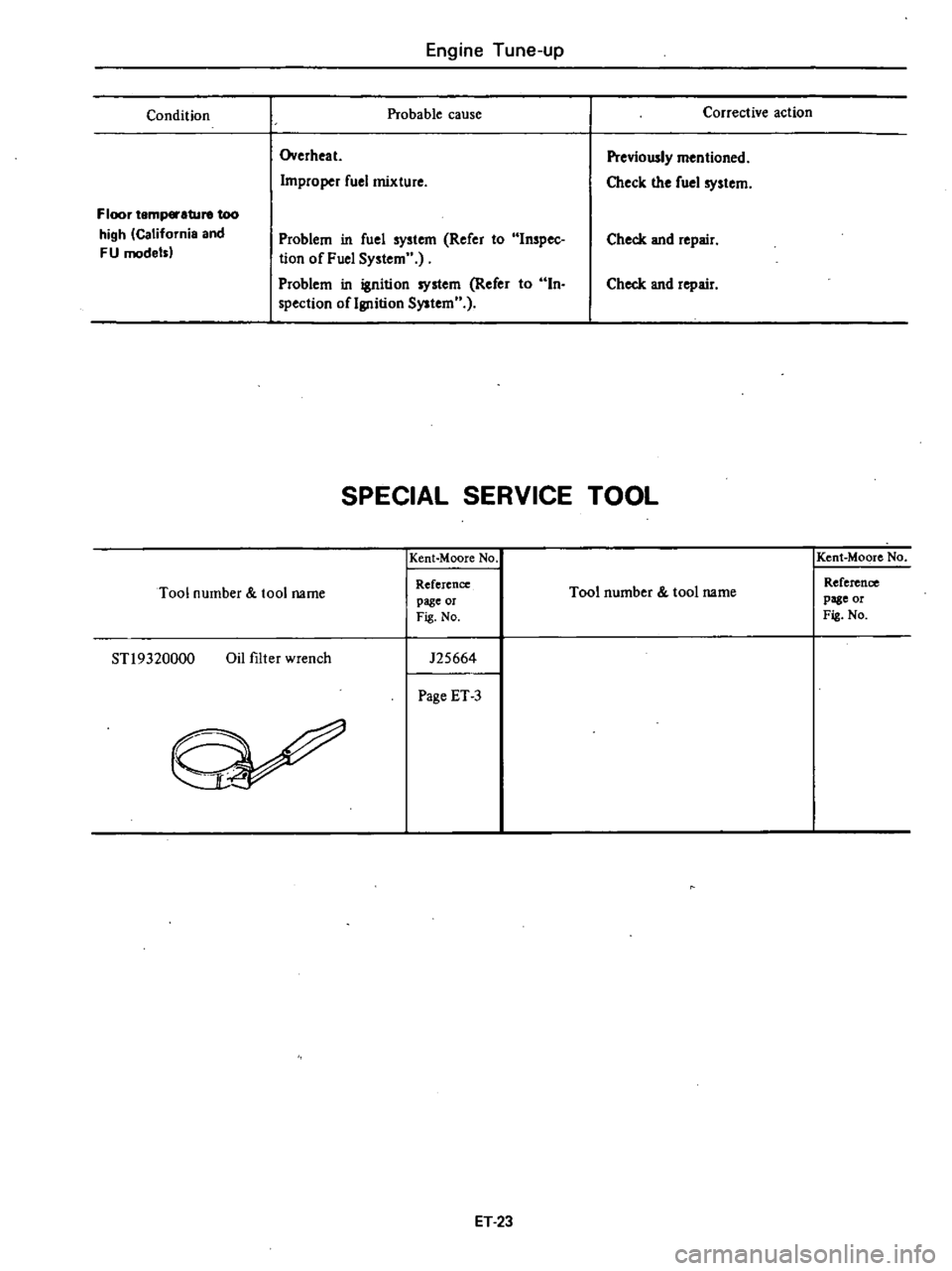
Engine
Tune
up
Condition
Probable
cause
Overheat
Improper
fuel
mixture
Floor
temp
ture
too
high
California
and
FU
model
Problem
in
fuel
system
Refer
to
Inspec
tion
of
Fuel
System
Problem
in
ignition
system
Refer
to
In
spection
oflgnition
System
Corrective
action
Previously
mentioned
Check
the
fuel
system
Check
and
repair
Check
and
repair
SPECIAL
SERVICE
TOOL
Kent
Moore
No
Tool
number
tool
name
Reference
page
or
Fig
No
STl9320000
Oil
filter
wrench
125664
Page
ET
3
ET
23
Kent
Moore
No
Tool
number
tool
name
Reference
page
or
Fig
No
Page 40 of 548
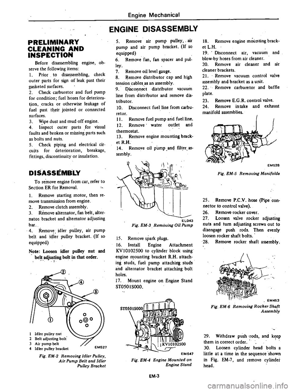
PRELIMINARY
CLEANING
AND
INSPECTION
Before
disassembling
engine
ob
serve
the
following
items
I
Prior
to
disassembling
check
outer
parts
for
sign
of
leak
past
their
gasketed
surfaces
2
Check
carburetor
and
fuel
pump
for
condition
fuel
hoses
for
deteriora
t
ion
cracks
or
otherwise
leakage
of
fuel
past
their
jointed
or
connected
surfaces
3
Wipe
dust
and
mud
off
engine
4
Inspect
outer
parts
for
visual
faults
and
broken
or
missing
parts
such
as
bolts
and
nuts
5
Check
piping
and
electrical
cir
cuits
for
deterioration
breakage
fittings
discontinuity
or
insulation
DISASSEMBLY
To
remove
engine
from
car
refer
to
Section
ER
for
Removal
1
Remove
starting
motor
then
re
move
transmission
from
engine
2
Remove
clutch
assembly
3
Remove
alternator
fan
belt
alter
nator
bracket
and
alternator
adjusting
bar
4
Remove
idler
pulley
air
pump
belt
and
idier
pulley
bracket
If
so
equipped
Note
Loosen
idler
pulley
nut
and
belt
adjusting
bolt
in
that
order
@
1
Idler
pulley
nut
2
Belt
adjusting
bolt
3
Air
pump
belt
4
Idler
pulley
bracket
EM527
Fig
EM
2
Removing
Idle
Pulley
Air
Pump
Belt
and
Idle
Pulley
Bracket
Engine
Mechanical
ENGINE
DISASSEMBLY
5
Remove
air
pump
pulley
air
pump
and
air
pump
bracket
If
so
equipped
6
Remove
fan
fan
spacer
and
pul
ley
7
Remove
oil
level
gauge
8
Remove
distributor
cap
and
high
tension
cables
as
an
assembly
9
Disconnect
distributor
vacuum
line
from
distributor
and
remove
dis
tributor
10
Disconnect
fuel
line
from
carbu
retor
II
Remove
fuel
pump
and
fuel
line
12
Remove
water
outlet
and
thermostat
13
Remove
engine
mounting
brack
et
R
H
14
Remove
oil
pump
and
filter
as
sembly
EL043
Fig
EM
3
Removing
Oil
Pump
15
Remove
spark
plugs
16
Install
Engine
Attachment
KVlOI02500
to
cylinder
block
using
engine
f1
ounling
bracket
R
H
attach
ing
studs
fuel
pump
attaching
studs
and
alternator
bracket
attaching
bolt
holes
17
Mount
engine
on
Engine
Stand
ST050I
SOOO
Fig
EM
4
EM
3
18
Remove
engine
mounting
brack
et
L
H
19
Disconnect
air
vacuum
and
blow
by
hoses
from
air
cleaner
20
Remove
air
cleaner
and
air
cleaner
brackets
21
Remove
vacuum
control
valve
assembly
and
bracket
as
a
unit
22
Remove
carburetor
and
baffle
plate
23
Remove
E
G
R
control
valve
24
Remove
intake
and
exhaust
manifold
assemblies
EM528
Fig
EM
5
Removing
Manifold
25
Remove
P
C
V
hose
pipe
con
nector
to
control
valve
26
Remove
rocker
cover
27
Loosen
valve
rocker
adjusting
nut
and
turn
adjusting
screws
out
to
disengage
push
rods
Then
evenly
loosen
rocker
shaft
bolts
28
Remove
rocker
shaft
assembly
EM453
Fig
EM
6
Removing
Rocker
Shaft
Assembly
29
Withdraw
push
rods
and
keep
them
in
correct
order
1
30
Loosen
cylinder
head
bolts
a
little
at
a
time
in
the
sequence
shown
in
Fig
EM
and
remove
cylinder
head
Page 86 of 548

DATSUN
210
Model
8310
Series
SECTIONEF
ENGINE
FUEL
CONTENTS
AUTOMATIC
TEMPERATURE
CONTROL
A
T
C
AIR
CLEANER
DESCRIPTION
OPERATION
REMOVAL
AND
INSTAllATION
INSPECTION
IDLE
COMPENSATOR
DESCRIPTION
INSPECTION
FUEL
FILTER
DESCRIPTION
FUEL
PUMP
OPERATING
TEST
REMOVAL
AND
INSTAllATION
DISASSEMBLY
EF
2
EF
2
EF
2
EF
3
EF
4
EF
5
EF
5
EF
5
EF
6
EF
6
EF
6
EF
6
EF
7
EF
7
INSPECTION
ASSEMBLY
CARBURETOR
DESCRIPTION
STRUCTURE
AND
OPERATION
INSPECTION
AND
ADJUSTMENT
MAJOR
SERVICE
OPERATION
TROUBLE
DIAGNOSES
AND
CORRECTIONS
SERVICE
DATA
AND
SPECIFICATIONS
GENERAL
SPECIFICATIONS
INSPECTION
AND
ADJUSTMENT
TIGHTENING
TORQUE
EF
7
EF
7
EF
B
EF
B
EF
B
EF
14
EF
23
EF
30
EF
32
EF
32
EF
32
EF
34
Page 89 of 548
TEMPERATURE
SENSOR
Removal
I
Using
pliers
flatten
clip
con
necting
vacuum
hose
to
sensor
vacuum
tube
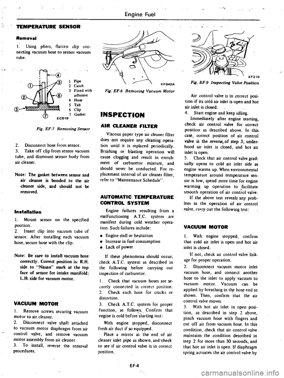
1
Pipe
2
Catch
3
Fixed
with
adhesive
4
Hose
5
Tab
6
Clip
7
Gasket
EC019
Fig
EF
7
Removing
Seruor
2
Disconnect
hose
from
sensor
3
Take
off
clip
from
sensor
vacuum
tube
and
dismount
sensor
body
from
air
cleaner
Note
The
gasket
between
sensor
and
air
cleaner
is
bonded
to
the
air
cleaner
side
and
should
not
be
removed
Installation
Mount
sensor
on
the
specified
position
2
Insert
clip
into
vacuum
tube
of
sensor
After
installing
each
vacuum
hose
secure
hose
with
the
clip
Note
Be
sure
to
install
vacUl
11n
hose
correctly
Correct
position
is
R
H
side
to
Ntisan
mark
at
the
top
face
of
sensor
for
intake
manifold
L
H
side
for
Deuum
motor
VACUUM
MOTOR
1
Remove
screws
securing
vacuum
motor
to
air
cleaner
2
Disconnect
valve
shaft
attached
to
vacuum
motor
diaphragm
from
air
control
valve
and
remove
vacuum
motor
assembly
from
air
cleaner
3
To
install
reverse
the
removal
procedures
Engine
Fuel
Fig
EF
8
Removing
Vacuum
Motor
INSPECTION
AIR
CLEANER
FILTER
Viscous
paper
type
air
cleaner
filter
does
o
ot
rt
quire
any
cleaning
opera
tion
until
it
is
replaced
periodically
Brushing
or
blasting
operation
will
cause
clogging
and
result
in
enrich
ment
of
carburetor
mixture
and
should
never
be
conducted
For
reo
placement
interval
of
air
cleaner
filter
refer
to
Maintenance
Schedule
AUTOMATIC
TEMPERATURE
CONTROL
SYSTEM
Engine
failures
resulting
from
a
malfunctioning
A
T
C
system
are
manifest
during
cold
weather
opera
tion
Such
failures
include
Engine
stall
or
hesitation
Increase
in
fuel
consumption
Lack
of
power
If
these
phenomena
should
occur
check
A
T
e
system
as
described
in
the
following
before
carrying
out
inspection
of
carburetor
I
Check
that
vacuum
hoses
are
se
l
urely
connected
in
correct
position
2
Check
each
hose
for
cracks
or
distortion
3
Check
A
T
C
system
for
proper
function
as
follo
ys
Confirm
that
engine
is
cold
before
starting
test
With
engine
topped
disconnect
fresh
air
duct
if
so
equipped
Place
a
mirror
at
the
end
of
air
cleaner
inlet
pipe
as
shown
and
check
to
see
if
air
control
valve
is
in
correct
position
EF
4
Fig
EF
9
Inspecting
Valve
Po
man
Air
control
valve
is
in
correct
posi
tion
if
its
cold
air
inlet
is
open
and
hot
air
inlet
is
closed
4
Start
engine
and
keep
idling
Immediately
after
engine
starting
check
air
control
valve
for
correct
position
as
described
above
In
this
case
correct
position
of
air
control
valve
is
the
reverse
of
step
3
under
hood
air
inlet
is
closed
and
hot
air
inlet
is
open
S
Check
that
air
control
valve
grad
ually
opens
to
cold
air
inlet
side
as
engine
warms
up
When
environmental
temperature
around
temperature
sen
sor
is
low
spend
more
time
for
engine
warming
up
operation
to
facilitate
smooth
operation
of
air
control
valve
If
the
above
test
reveals
any
prob
lem
in
the
opera
ion
of
air
control
valve
carry
out
the
following
test
VACUUM
MOTOR
I
With
engine
stopped
confirm
that
cold
air
inlet
is
open
and
hot
air
inlet
is
c1
Sed
If
not
check
air
control
valve
link
age
for
proper
operation
2
DiscoJln
ct
ac
um
motor
inlet
vacuum
hose
and
connect
another
hose
to
the
inlet
to
apply
vacuum
to
vacuum
motor
Vacuum
can
be
appli
d
by
breathing
in
tile
hos
e
end
as
shown
Then
confirm
that
the
air
control
valve
moves
3
With
hot
air
inlet
in
open
posi
tion
as
described
in
step
2
above
pinch
vacuum
hose
with
fingers
and
cut
off
air
from
vacuum
hose
In
this
condition
check
that
air
control
valve
maintains
the
condition
described
in
step
2
for
more
than
30
seconds
and
that
hot
air
inlet
is
open
If
diaphragm
spring
actuates
the
air
control
valve
by
Page 91 of 548
Engine
Fuel
S
Idle
compensator
is
ill
good
order
if
a
hissing
sound
is
heard
when
its
temperature
reaches
operating
tern
perature
If
not
replace
idle
compensator
ldlerompensator
l
b
l
r
I
No
1
60
to
700C
140
to
15
Of
No
2
70
to
800C
158
to
1760F
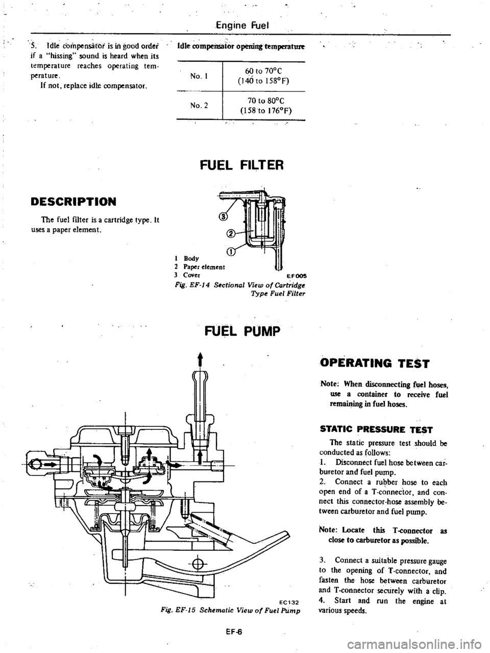
FUEL
FILTER
DESCRIPTION
t
t
I
J
i
l
The
fuel
filter
is
a
cartridge
type
It
useS
a
paper
element
1
Body
2
Paper
element
3
Cover
EFOOS
Fig
EF
14
Sectional
View
of
Cartridge
Type
FuelFilte
FUEL
PUMP
t
j
f
EC132
Fig
EF
15
Schematic
View
of
Fuel
Pump
EF
6
OPERATING
TEST
Note
When
disconnecting
fuel
hoses
me
a
container
to
receive
fuel
remaining
in
fuel
hoses
STATIC
PRESSURE
TEST
The
static
pressure
test
should
be
conducted
as
follows
I
Disconnect
fuel
hose
between
car
buretor
and
fuel
pump
2
Connect
a
rubber
hose
to
each
open
end
of
aT
connector
and
con
nect
this
connector
hose
assembly
be
tween
carburetor
and
fuel
pump
Note
Locate
this
T
eonnector
as
close
to
carburetor
as
possible
3
Connect
a
suitable
pressure
gauge
to
the
opening
of
T
connector
and
fasten
the
hose
between
carburetor
and
T
connector
secUrely
with
a
clip
4
Start
and
run
the
engine
at
various
speeds
Page 95 of 548
I
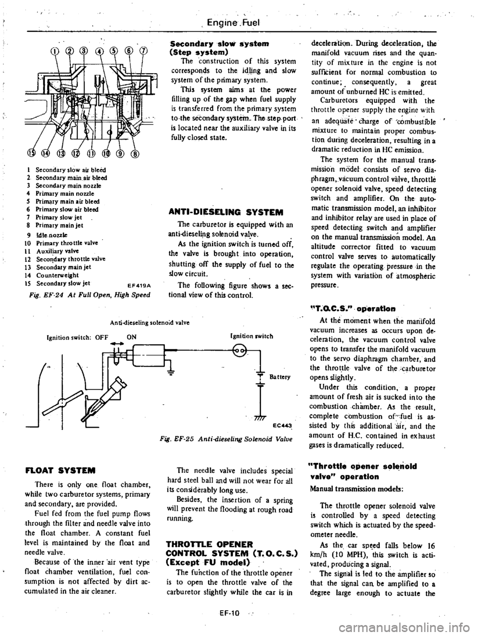
Secondary
slow
air
bleed
2
Secondary
main
air
bleed
3
Secondary
main
nozzle
4
Primary
main
nozzle
5
Primary
main
air
bleed
6
Primary
slow
air
bleed
7
Primary
slow
jet
8
Primary
main
jet
9
Idle
nozzle
10
Primary
throttle
valve
II
Auxiliary
valve
12
Seco
dary
throttle
valve
13
Secondary
main
jet
14
Counterweight
IS
Secondary
slow
jet
EF419A
Fig
EF
24
At
Full
Open
High
Speed
Engine
Fuel
Secondary
slow
system
Step
system
The
construction
of
this
system
corresponds
to
the
idling
and
slow
system
of
the
primary
system
This
system
aims
at
the
power
filling
up
of
the
gap
when
fuel
supply
is
transferred
from
the
primary
system
to
the
secondary
system
The
stepport
is
located
near
the
auxiliary
valve
in
its
fully
closed
state
ANTI
DIESELING
SYSTEM
The
carburetor
is
equipped
with
an
anti
liese1i
lg
solenoid
valye
As
the
ignition
switch
is
turned
off
the
valve
is
brought
into
operation
shutting
off
the
supply
of
fuel
to
the
slow
circuit
The
following
figure
shows
a
see
tional
view
of
this
control
An
ti
dies
eling
solenoid
valve
Ignition
switch
OFF
ON
t
L
li
FLOAT
SYSTEM
There
is
only
one
float
chamber
while
two
carburetor
systems
primary
and
secondary
are
provided
Fuel
fed
from
the
fuel
pump
flows
through
the
filter
and
needle
valve
into
the
float
chamber
A
constant
fuel
level
is
maintained
by
the
float
and
needle
valve
Because
of
the
inner
air
vent
type
float
chamber
ventilation
fuel
con
sumption
is
not
affected
by
dirt
ac
cumulated
in
the
air
cleaner
Ignition
switch
Q
1
T
Battery
niT
EC
3
Fig
EF
25
Anti
dieseling
Solenoid
Valve
The
needle
valve
includes
special
hard
steel
ball
and
wiD
not
wear
for
all
its
considerably
long
use
Besides
the
insertion
of
a
spring
will
prevent
the
flooding
at
rough
road
running
THROTTLE
OPENER
CONTROL
SYSTEM
T
O
C
S
Except
FU
model
The
function
of
the
throttle
opener
is
to
open
the
throttle
valve
of
the
carburetor
slightly
while
the
car
is
in
EF
10
deceleration
During
deceleration
the
manifold
vacuum
rises
and
the
quan
tity
of
mixture
in
the
engine
is
not
suffICient
for
normal
combustion
to
continue
4
consequently
a
great
amount
of
unburned
HC
is
emitted
Carburetors
equipped
with
the
throttle
opener
supply
the
engine
with
an
adequate
charge
of
combustible
mixture
to
maintain
proper
combus
tion
during
deceleration
resulting
in
a
dramatic
reduction
in
HC
emission
The
system
for
the
manual
trans
mission
model
consists
of
servo
dia
phragm
vlicuum
control
valve
throttle
opener
solenoid
valve
spee
l
detecting
switch
and
amplifier
On
the
auto
matic
transmission
model
an
inhibitor
and
inhibitor
relay
are
used
in
place
of
speed
detecting
switch
and
amplifier
on
the
manual
transmission
model
An
altitude
corrector
fitted
to
vacuum
control
valve
serves
to
automatically
regulate
the
operating
pressure
in
the
system
with
variation
of
atmospheric
pressure
T
o
C
S
n
operatIon
At
the
moment
when
the
manifold
vacuum
increases
as
occurs
upon
de
celeration
the
vacuum
control
valve
opens
to
transfer
the
manifold
vacuum
to
the
servo
diaphragm
chamber
and
the
throttle
valve
of
the
carburetor
opens
slightly
Under
this
condition
a
proper
amount
of
fresh
air
is
sucked
into
the
combustion
chamber
As
the
result
complete
combustion
of
fuel
is
as
sisted
by
this
additional
air
and
the
amount
of
H
C
contained
in
exhaust
gases
is
dramatically
reduced
Throttle
Clpener
sol
nold
valve
operation
Manual
transmission
models
The
throttle
opener
solenoid
valve
is
controlled
by
a
speed
detecting
switch
which
is
actuated
by
the
speed
ometer
needle
As
the
car
sp
ed
falls
below
16
km
h
10
MPH
this
switch
is
acti
vated
producing
a
signal
The
signal
is
led
to
the
amplifier
so
that
the
signal
can
be
amplified
to
a
degree
large
enough
to
actuate
the
Page 114 of 548
CLEANING
AND
INSPECTION
Dirt
gum
water
or
carbon
con
tamination
in
or
on
exterior
moving
parts
of
a
carburetor
are
often
respon
sible
for
unsatisfactory
performance
For
this
reason
efficient
carhuretion
depends
upon
careful
cleaning
and
inspection
while
servicing
Blow
all
passages
and
castings
with
compressed
air
and
blow
off
all
parts
until
dry
Note
Do
not
pass
drills
or
wires
through
calibrated
jets
or
passages
as
this
may
enlarge
orifice
and
seriously
affect
carburetor
calibra
tion
2
Check
all
parts
for
wear
If
wear
is
noted
damaged
parts
must
be
re
placed
Note
especially
the
following
I
Check
float
needle
and
seat
for
wear
If
wear
is
noted
assembly
must
be
replaced
2
Check
throttle
and
choke
shaft
bores
in
throttle
chamber
and
choke
chamber
for
wear
or
out
of
roundness
3
Inspect
idle
adjusting
needle
for
hurrs
or
ridges
Such
a
condition
re
quires
replacement
Engine
Fuel
3
Inspect
gaskets
to
see
if
they
appear
hard
or
brittle
or
if
edges
are
torn
or
distorted
If
any
such
condi
tion
is
noted
they
must
be
replaced
4
Check
filter
screen
for
dirt
or
lint
Clean
and
if
screen
is
distorted
or
remains
plugged
replace
5
Check
linkage
for
operating
condition
6
Inspect
operation
of
accelerating
pump
Pour
fuel
into
float
chamber
and
make
throttle
lever
operate
Check
condition
of
fuel
injection
from
the
accelerating
nome
7
Push
connecting
rod
of
dia
phragm
chamber
and
block
passage
of
vacuum
with
finger
When
connecting
rod
becomes
free
check
for
leakage
of
air
or
damage
to
diaphragm
Jets
Carburetor
performance
depend
on
jets
and
air
bleeds
That
is
why
these
components
must
be
fabricated
with
utmost
care
To
clean
them
use
cleaning
solvent
and
blow
air
on
them
Larger
inner
nwnbers
stamped
on
the
EF
29
jets
indicate
larger
diameters
Ac
cordingIy
main
and
slow
jets
with
larger
numbers
provide
richer
mixture
the
smaller
numbers
the
leaner
mix
ture
Conversely
the
main
and
slow
air
bleeds
through
which
air
to
passes
make
the
fuel
leaner
if
they
bear
larger
numbers
the
smaller
numbers
the
richer
fuel
Assembly
To
assemble
reverse
the
disassem
bly
procedure
taking
care
to
the
following
I
Thoroughly
wash
all
the
parts
before
assembling
2
Inspect
gaskets
to
see
if
they
appear
hard
or
brittle
or
if
edges
are
torn
or
distorted
If
any
of
such
undesirable
condi
tions
is
noted
they
must
be
replaced
3
Install
jet
and
air
bleed
having
the
Same
size
number
as
that
of
original
one
4
After
reassembling
carburetor
check
each
rotating
portion
or
sliding
portion
for
smooth
operation
Page 115 of 548

Engine
fuel
TROUBLE
DIAGNOSES
AND
CORRECTIONS
In
the
following
table
the
symp
toms
and
causes
of
carburetor
troubles
and
remedies
for
them
are
listed
to
facilitate
quick
repairs
There
are
various
causes
of
engine
malfunctions
It
sometimes
happens
that
a
carburetor
which
has
no
fault
appears
to
have
some
problems
when
Condition
Probable
cause
Overflow
Dirt
accumulated
on
needle
valve
Fuel
pump
pressure
too
high
Needle
valve
improperly
seated
Excessive
fuel
consumption
Fuel
overflow
Slow
jet
too
large
on
each
main
jet
Main
air
bleed
clogged
Choke
valve
does
not
open
fully
Outlet
valve
seat
of
accelerator
pump
improper
Unked
opening
of
secondary
throttle
valve
opens
ioo
early
Power
shortage
Mainjels
clogged
Every
throttle
valve
Joes
not
open
fully
Idling
adjustment
incorrect
Fuel
filter
clo
ll
ed
Vacuum
jet
clogged
Air
cleaner
clogged
Diaphragm
damaged
Power
valve
operating
improperly
Improper
idling
Slow
jet
clogged
Every
throttle
valve
does
not
close
Secondary
throttle
valve
operating
im
properly
Throttle
valve
shafts
wom
Packing
between
manifold
carburetor
faulty
Manifold
carburetor
tightening
improper
Fuel
overflow
T
O
C
S
adjustment
incorrect
Vacuum
control
solenoid
damaged
Stuck
dash
pot
EF
30
acfuaJIy
theelectric
syslem
i
at
fatilt
Therefore
whenever
the
engine
is
mal
functioning
the
electrical
system
should
be
checked
fust
before
adjust
ing
carburetor
Corrective
action
Clean
needle
valve
Repair
pump
Replace
See
above
item
Replace
Clean
Adjust
Lap
Adjust
Clean
Adjust
Repair
Repair
Clean
Clean
Replace
Adjust
Clean
Adjust
Overhaul
and
clean
Replace
Replace
packing
Correct
tightening
See
the
first
item
Adjust
Replace
Replace