wheel torque DATSUN 210 1979 Workshop Manual
[x] Cancel search | Manufacturer: DATSUN, Model Year: 1979, Model line: 210, Model: DATSUN 210 1979Pages: 548, PDF Size: 28.66 MB
Page 419 of 548

Body
2
Length
of
shock
absorber
Front
shock
absorber
I
164
6
46
q
j
0
I
0
0
67
2
64
Rear
shock
absorber
G
riA
l
yll
L
J
J
Unit
mm
in
3
Checking
shock
absorber
I
Place
car
in
front
of
a
wall
Apply
hand
brake
and
place
wheel
chocks
securely
2
Place
a
jack
between
wall
and
extend
jack
approximately
20
mm
0
79
in
The
bumper
should
move
approxilnately
50
mm
I
97
in
back
ward
through
shock
absorber
opera
tion
See
Fig
BF
IO
Note
Use
a
jack
with
y
of
more
than
600
kg
I
3231b
94
3
70
rL
I
i
r
T
l
f
L
W
67
2
64
1
8F742B
Fig
BF
9
Length
of
Shock
Absorber
3
Make
sure
bumper
returns
to
its
original
position
when
jack
is
re
tracted
Note
When
replacing
shock
absorb
ers
make
Sure
they
are
of
the
same
type
and
rating
and
manufactured
by
the
same
maker
4
For
rear
bumper
utilize
the
same
procedures
as
described
for
front
bumper
f
BF7438
1
Front
bumper
2
Jack
3
Wheel
chock
Fig
BF
10
Checking
Shock
Abaorber
Function
BF
8
FRONT
BUMPER
REMOVAL
AND
INSTALLATION
1
Loosen
bolts
attaching
front
bumper
to
shock
absorbers
and
re
move
bumper
See
Fig
BF
5
2
Loosen
bolts
attaching
shock
ab
sorbers
to
radia
tor
core
support
and
side
members
and
remove
shock
absorbers
3
Install
shock
absorbers
and
front
bumper
in
reverse
order
of
removal
and
adjust
bumper
height
as
shown
in
Fig
BF
7
fj
Tightening
torque
Front
bumper
Bumper
to
shock
absorber
attaching
bolt
6
0
to
8
0
kg
m
43
to
58
ft
Ib
Shock
absorber
to
body
attaching
bolt
and
nut
front
0
93
to
1
2
kg
m
6
7
to
B
7
ft
Ibl
attaching
bolt
and
nut
sida
1
9
to
2
5
kg
m
14
to
18
ft
b
REAR
BUMPER
REMOVAL
AND
INSTALLATION
1
Loosen
bolts
attaching
rear
bumper
to
shock
absorbers
and
re
move
rear
bumper
See
Fig
BF
6
2
Loosen
bolts
and
nuts
attaching
shock
absorbers
to
side
members
and
remove
shock
absorbers
3
Install
shock
absorbers
an
rear
bumper
in
reverse
order
of
removal
and
adjust
rear
bumper
height
as
shown
in
Fig
BF
B
fj
Tightening
torque
Rear
bumper
Bumper
to
shock
absorber
attaching
bolt
rear
6
0
to
8
0
kg
m
43
to
58
ft
b
Shock
absorber
to
body
attaching
bolt
and
nut
rear
0
93
to
1
2
kg
m
6
7
to
8
7
ft
b
attaching
bolt
and
nut
side
6
0
to
BoO
kg
m
43
to
58
ft
b
Page 527 of 548

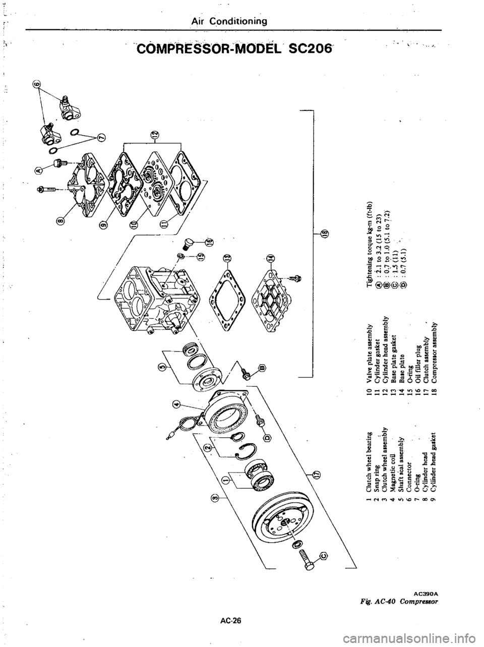
0
@
o
s
xl
m
u
U
0
0
xJ
l
1
I
9
0
I
K
s
0
0
en
o
o
l
me
0
r
U
0
I
@
0
0
Tightening
torque
kg
m
ft
Ib
I
Clutch
wheel
bearing
10
Valve
pla
te
assembly
2
Snap
ring
11
Cylinder
gasket
@
i
1
to
3
2
IS
to
23
C
l
3
Clutch
wheel
alsembly
12
Cylinder
head
assembly
@
O
to
1
0
5
1
to
7
2
0
4
Magnetic
coil
13
B
plate
gasket
@
1
5
11
5
Shaft
seal
assembly
14
Bale
plate
@
0
7
5
1
6
Connector
IS
a
ting
7
O
ring
16
au
filler
plug
i
8
Cylindet
head
17
Clutch
assembly
o
Q
9
CyUhder
head
gasket
18
Compreslor
assembly
Page 528 of 548

PRELIMINARY
CLEANING
Before
starting
work
remove
dirt
from
outside
the
detached
compressor
Clean
the
workbench
tool
and
your
hands
COMPRESSOR
CLUTCH
The
most
likely
source
of
problem
is
clutch
slippage
Factors
are
listed
here
Exercise
ample
care
1
Clearance
between
clutch
hub
and
pulley
should
be
0
4
to
0
6
mm
0
016
to
0
024
in
at
aU
peripheral
points
2
Make
sure
that
there
is
no
oil
or
dirt
on
friction
surfaces
of
clutch
disc
clutch
hub
and
pulley
Remove
oil
or
dirt
with
clean
lint
free
cloth
3
Make
sure
that
terminal
voltage
at
magnetic
coil
is
above
10
5V
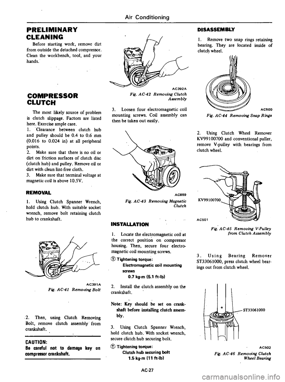
REMOVAL
I
Using
Clutch
Spanner
Wrench
hold
clutch
hub
With
suitable
socket
wrench
remove
bolt
retaining
clutch
hub
to
crankshaft
AC391A
Fig
AC
41
Removing
Bolt
2
Then
using
Clutch
Removing
Bolt
remove
clutch
assembly
from
crankshaft
CAUTION
Be
careful
not
to
demage
key
on
compressor
crankshaft
Air
Conditioning
AC392A
Fig
AC
42
Removing
Clutch
Assembly
3
Loosen
four
electromagnetic
coil
mounting
screws
Coil
assembly
can
then
be
taken
out
easily
AC869
Fig
AC
43
R
mouing
Magnetic
Clutch
INSTALLATION
Locate
the
electromagnetic
coil
at
the
correct
position
on
compressor
housing
Then
secure
four
electro
magnetic
coil
mounting
screws
@
Tightening
torque
Electromagnetic
coil
mounting
screws
0
7
kltm
5
1
ft
Ibl
2
InstaU
the
clutch
assembly
on
the
crankshaft
Note
Key
should
be
set
on
crank
shaft
before
installing
clutch
assem
bly
3
Using
Clutch
Spanner
Wrench
hold
clutch
hub
With
socket
wrench
secure
clutch
hub
securing
bolt
iJJ
Tightening
torque
Clutch
hub
securing
bolt
1
5
kg
m
11
ft
Ib
AC
27
DISASSEMBLY
1
Remove
two
snap
rings
retaining
bearing
They
are
located
inside
of
clutch
wheel
I
AC500
Fig
AC
44
Removing
Snap
Ring
2
Using
Clutch
Wheel
Remover
KV99100700
and
conventional
puller
remove
V
pulley
with
bearings
from
clutch
wheel
KV99100100
AC501
Fig
AC
45
Removing
V
Pulley
from
Clutch
Assembly
3
Us
i
n
g
Bearing
Remover
ST33061000
press
clutch
wheel
bear
ings
out
from
clutch
wheel
ST33061000
I
Jiffi
I
ACSD2
Fig
AC
46
Removing
Clutch
Wheel
Bearing