service schedule DATSUN 210 1979 Service Manual
[x] Cancel search | Manufacturer: DATSUN, Model Year: 1979, Model line: 210, Model: DATSUN 210 1979Pages: 548, PDF Size: 28.66 MB
Page 14 of 548

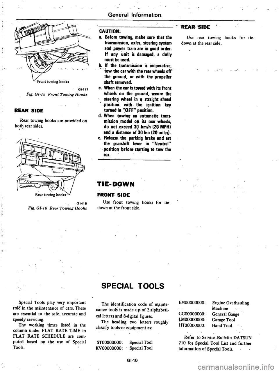
GI417
Fig
GI
15
Front
Towing
Hook
REAR
SIDE
Rear
towing
hooks
are
provided
on
bot
rear
sides
GI418
Fig
GI
16
Rear
Towing
Hooks
Special
Tools
play
very
important
role
in
the
maintenance
of
cars
These
are
essential
to
the
safe
accurate
and
speedy
servicing
The
working
times
listed
in
the
column
under
FLAT
RATE
TIME
in
FLAT
RATE
SCHEDULE
are
com
puted
based
on
the
use
of
Special
Tools
General
Information
CAUTION
a
Before
towing
make
sure
that
the
transmission
axles
steering
system
and
p
r
train
are
in
good
order
If
any
unit
is
damaged
a
dolly
must
be
used
If
the
transmission
is
inoperative
tow
the
car
with
the
rear
wheels
off
the
ground
or
with
the
propeller
shaft
removed
c
When
the
car
is
towed
with
its
front
wheels
on
the
ground
secure
the
steering
wheel
in
a
straight
ahead
position
with
the
ignition
key
turnedin
OFF
position
d
When
towing
an
automatic
trans
mission
model
on
its
rear
wheels
do
not
exceed
30
km
h
20
MPH
and
a
distance
of30
km
20
miles
e
Release
the
parking
brake
and
set
the
gearshift
lever
in
Neutral
position
before
starting
to
tow
the
car
TIE
DOWN
FRONT
51
DE
Use
front
towing
hooks
for
tie
down
at
the
front
side
SPECIAL
TOOLS
The
identification
code
of
ffi
linte
nance
tools
is
made
up
of
2
alphabeti
calletters
and
8
digital
figures
The
heading
two
letters
roughly
classify
tools
c
equipment
as
STOOOOOOOO
KVOOOOOOOO
Special
Tool
Special
Tool
GI
l0
REAR
SIDE
Use
rear
towing
hooks
for
tie
down
at
the
rear
side
EMOOOOOOOO
GGOOOOOOOO
lMOOOOOOOO
HTOOOOOOOO
Engine
Overhauling
Machine
General
Gauge
Garage
Tool
Hand
Tool
Refer
to
Service
Bulletin
DATSUN
210
fOJ
Special
Tool
List
and
further
information
of
Special
Tools
Page 181 of 548

CHECKING
AND
ADJUSTMENT
CAP
AND
ROTOR
HEAD
Cap
and
rotor
head
should
be
in
spected
periodically
as
specified
in
the
Main
teoanee
Schedule
Remove
cap
and
clean
all
dust
and
carbon
deposits
from
cap
and
rotor
from
time
to
time
If
cap
is
cracked
or
is
leaking
replace
wi
th
a
new
one
ADVANCE
MECHANISMS
SpecHlcatlons
Refer
to
Service
Data
and
Specifica
tions
for
distributor
Vacuum
advance
mechanism
mechanical
parts
If
vacuum
advance
mechanism
fails
to
operate
properly
check
for
the
followin
B
items
and
correct
the
mal
function
as
required
I
Check
vacuum
inlet
for
signs
of
leakage
at
its
connection
If
necessary
retighten
or
replace
with
a
new
one
2
Check
vacuum
diaphragm
for
air
leak
If
leak
is
found
replace
vacuum
controUer
assembly
3
Inspect
breaker
plate
for
smooth
moving
If
plate
does
not
move
smoothly
this
condition
could
be
due
to
sticky
steel
balls
or
pivot
Apply
grease
to
steel
halls
or
if
necessary
replace
breaker
plate
as
an
assembly
Centrifugal
advance
mechanical
parts
When
cause
of
engine
malfunction
is
traced
to
centrifugal
advance
mecha
nical
parts
use
distributor
tester
to
check
its
characteristics
If
nothing
is
wrong
with
its
charac
teristics
conceivable
causes
are
faulty
or
abnormal
wear
of
driving
part
or
others
So
do
not
disassemble
it
In
the
event
of
improper
character
istics
check
closely
rotor
shaft
assem
bly
governor
weight
and
shaft
If
any
of
the
above
parts
are
mal
functioning
replace
the
parts
Engine
Electrical
System
DISASSEMBLY
AND
ASSEMBLY
DISASSEMBLY
I
Take
off
cap
and
remove
rotor
head
2
Remove
Ie
ignition
unit
Refer
to
IC
Ignition
Unit
for
removal
and
in
stallation
3
Remove
stator
and
magnet
by
removing
stator
securing
screws
4
Remove
vacuum
controller
by
removing
securing
screws
EE746
Fig
EE
59
Removing
Vacuum
Controller
5
Using
two
pry
bars
or
suitable
puller
pry
reluctor
from
shaft
CAUTION
When
removing
reluctor
be
careful
not
10
distort
or
damage
the
teeth
6
Remove
roll
pin
7
Remove
pick
up
coil
assembly
8
Remove
breaker
plate
setscrews
and
remove
breaker
plate
assembly
EE703
Fig
EE
60
Removing
Breaker
Plate
Setscrews
9
Punch
knock
pin
out
and
remove
pinion
EE
23
EE704
Fig
EE
61
Removing
Knock
Pin
10
Remove
rotor
shaft
and
drive
shaft
assembly
EE705
Fig
EE
62
Removing
Rotor
Shaft
and
Drive
Shaft
Assembly
11
Mark
rotor
shaft
and
drive
shaft
Remove
packing
from
the
top
of
rotor
shaft
and
unscrew
rotor
shaft
setscrew
Remove
rotor
shaft
EE706
Fig
EE
63
Removing
Rotor
Shaft
12
Mark
one
of
the
governor
springs
and
its
bracket
Also
mark
one
of
the
governor
weights
and
its
pivot
pins
13
Carerully
unhook
and
remove
governor
springs
14
Remove
governor
weights
A
r
ply
grease
to
guvernor
weights
after
disassembling