DATSUN 510 1968 Service Manual PDF
Manufacturer: DATSUN, Model Year: 1968, Model line: 510, Model: DATSUN 510 1968Pages: 252, PDF Size: 12.2 MB
Page 71 of 252
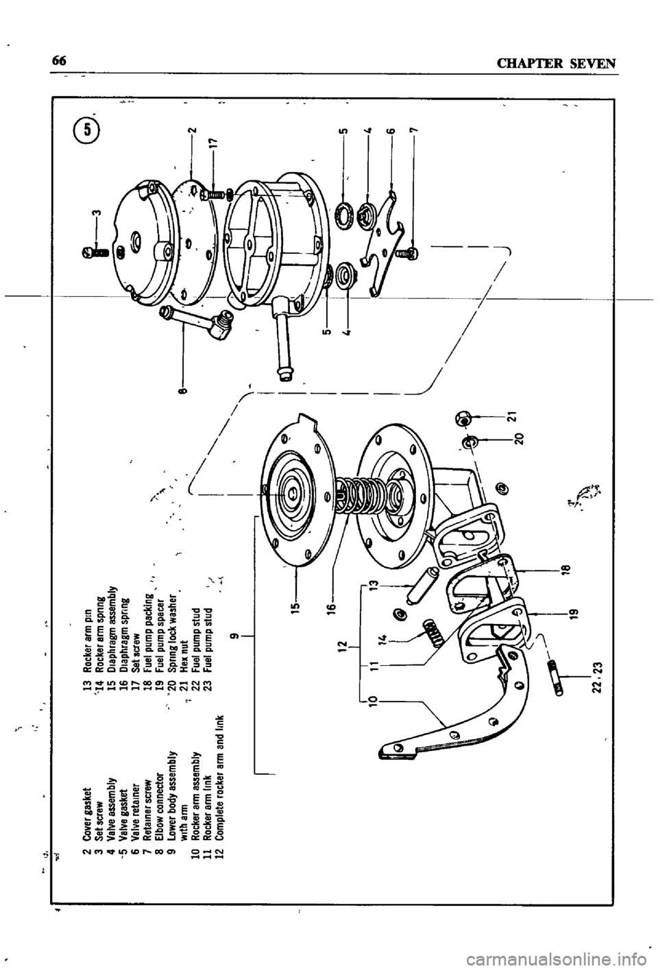
01
01
G
1
3
2
Co
er
gasket
3
Set
screw
4
Val
e
assembly
5
Val
e
gasket
6
Val
e
retelner
7
Retainer
screw
8
Elbow
connector
9
lower
body
assembly
With
arm
10
Rocker
arm
assembly
11
Rocker
arm
link
12
Complete
rocker
arm
and
link
13
Rocker
arm
pin
14
Rocker
arm
spnng
15
Dlephragm
assembly
16
Diaphragm
spring
17
Sehcrew
18
Fuel
pump
pecking
19
Fuel
pump
spacer
20
Spnng
lock
washer
21
Hex
nut
22
Fuel
pump
stud
23
Fuel
pump
stud
2
17
r
I
I
I
I
I
I
I
I
I
J
9
I
I
15
I
0
5
I
16
1i
20
21
g
tI
i
I
lb
18
22
23
r
Page 72 of 252
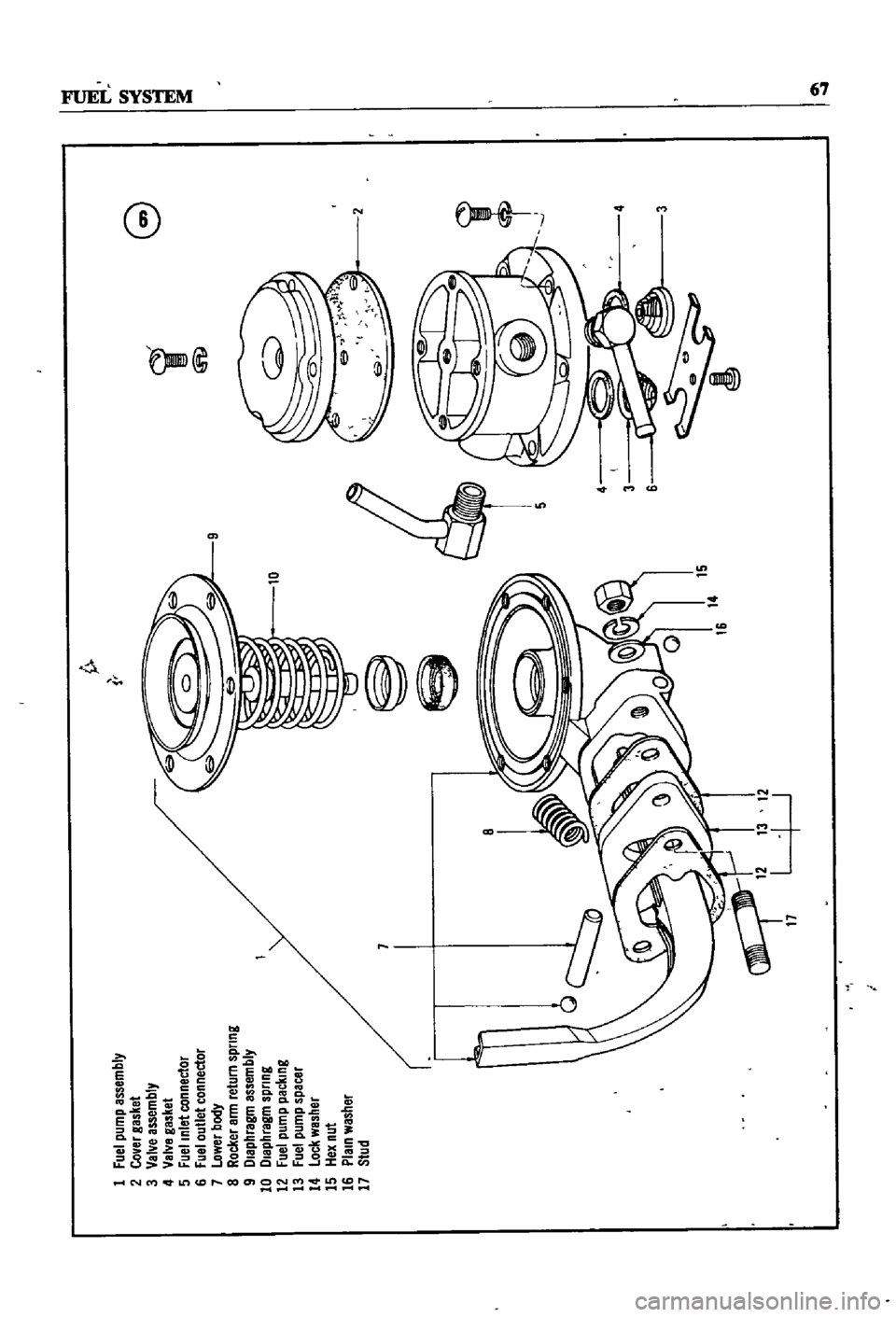
G
i
@
1
fuel
pump
assembly
2
CoVBr
gasket
3
VBNB
assemblY
4
VBNB
gBsl
et
5
Fuel
Inlet
connect01
6
fUBI
outlet
connector
7
OwerllodY
a
Rocker
Bll
Ireturn
spnng
9
l
IBP
1rBgm
BssemblY
10
l
IBphlBgm
sQnng
12
Fuel
QumQ
packIng
13
fuel
pump
spBcer
14
lOc
l
wBsl
er
15
lex
nut
16
PIBIn
was
1Br
17
Stud
Page 73 of 252
68
CHAPTER
SEVEN
Capacity
Test
Perform
the
capacity
test
only
when
the
statIc
pressiue
test
IS
withm
acceptable
lirmts
1
D
sconnect
the
fuellme
at
the
carburetor
2
Place
a
sUItable
container
at
the
end
of
the
fuellme
3
St
lrt
the
engm
and
run
at
OOO
rpm
4
The
fuel
pump
should
delIver
fuel
into
the
co
ntainer
at
a
rate
slightly
over
two
pints
per
minute
If
no
gasolme
or
only
a
lIttle
appears
the
fuel
lme
is
clogged
or
thefuel
pump
defectIve
Bef
removmg
the
fuel
pump
remove
the
gas
tank
filler
cap
dtsconnect
the
mlet
and
outlet
fuel
lmes
and
qlow
through
them
With
compressed
air
to
make
certam
they
are
clear
Reconnect
the
fuellmes
and
retest
the
flow
If
stIll
insufficient
the
fuel
p
mp
requires
servicmg
or
replacement
Fuel
Punip
Removal
and
Disassembly
1
Unscrew
the
two
mountIng
nuts
hOldmg
fuel
pump
to
the
cylmder
head
2
Disconnect
the
inlet
and
outlet
lines
3
Remove
the
fuel
pump
from
the
cylmder
head
4
Place
the
pump
on
a
work
bench
and
remove
the
screws
jommg
the
upper
and
lower
bodIes
5
Remove
the
cap
and
gasket
by
removing
the
cap
screws
6
Unscrew
the
elbow
and
connector
7
Remove
the
valve
retamer
by
unscrewmg
the
two
valve
retamer
screws
The
two
valves
are
then
easily
removed
8
To
remove
the
dIaphragm
spring
lower
body
seal
washer
and
lower
body
seal
from
the
lower
body
press
the
diaphragm
down
Wh1le
domg
thIS
cant
the
dIaphragm
so
that
the
rectangular
part
m
the
lower
end
of
the
pull
rod
unhooks
from
the
rocker
arm
lmk
ThIS
action
IS
shown
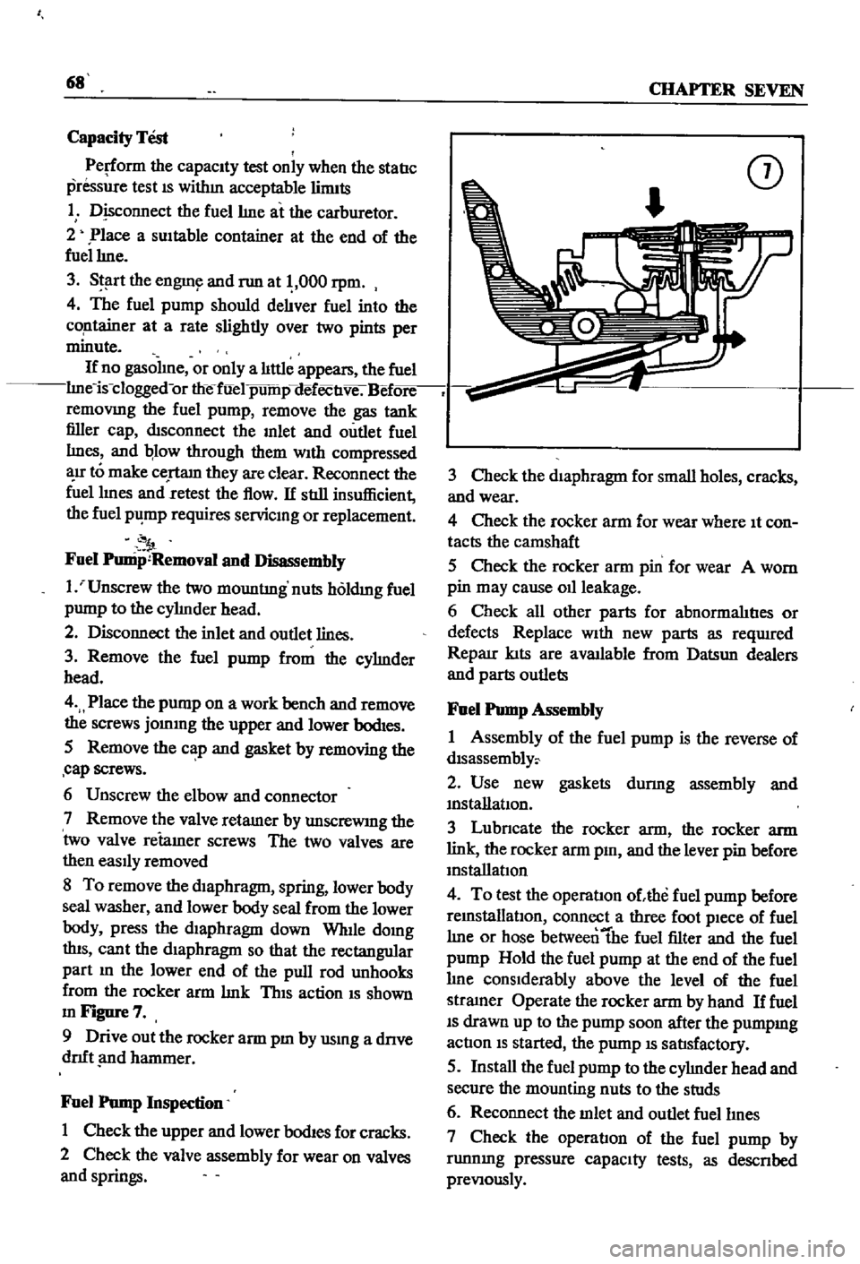
mFigure7
9
Drive
out
the
rocker
arm
pm
by
usmg
a
dnve
dnft
nd
hammer
Fuel
Pump
Inspection
1
Check
the
upper
and
lower
bodIes
for
cracks
2
Check
the
valve
assembly
for
wear
on
valves
and
springs
CD
3
Check
the
diaphragm
for
small
holes
cracks
and
wear
4
Check
the
rocker
arm
for
wear
where
It
con
tacts
the
camshaft
5
Check
the
rocker
arm
pin
for
wear
A
worn
pin
may
cause
011
leakage
6
Check
all
other
parts
for
abnormalItIes
or
defects
Replace
With
new
parts
as
reqUlred
Reparr
kIts
are
available
from
Datsun
dealers
and
parts
outlets
Fuel
Pump
Assembly
1
Assembly
of
the
fuel
pump
is
the
reverse
of
dlsassembly
2
Use
new
gaskets
durmg
assembly
and
mstanatIon
3
Lubncate
the
rocker
arm
the
rocker
arm
link
the
rocker
arm
pm
and
the
lever
pin
before
mstallatIon
4
To
test
the
operatIon
ohhe
fuel
pump
before
remstallatlOn
connect
a
three
foot
pIece
of
fuel
lme
or
hose
betweentbe
fuel
filter
and
the
fuel
pump
Hold
the
fuel
pump
at
the
end
of
the
fuel
lme
conSIderably
above
the
level
of
the
fuel
stramer
Operate
the
rocker
arm
by
hand
If
fuel
IS
drawn
up
to
the
pump
soon
after
the
pumpmg
actIon
IS
started
the
pump
IS
satIsfactory
5
Install
the
fuel
pump
to
the
cylmder
head
and
secure
the
mounting
nuts
to
the
studs
6
Reconnect
the
mlet
and
outlet
fuellmes
7
Check
the
operatIon
of
the
fuel
pump
by
runnmg
pressure
capaCIty
tests
as
descnbed
preVIously
Page 74 of 252
FUEL
SYSTEM
69
CARBURETOR
The
carburetor
IS
an
Hltach1
Type
DAF328
Several
varIations
are
used
dependmg
on
the
model
year
type
of
transmissIOn
and
the
emIS
SIon
control
system
The
dIfferent
models
are
the
same
as
far
as
basiC
operation
IS
concerned
Therefore
the
followmg
dISCUSSIon
covers
a
typIcal
carburetor
The
automatIc
choke
IS
used
on
automatIc
transmISSIon
and
1972
models
only
All
other
chokes
are
manual
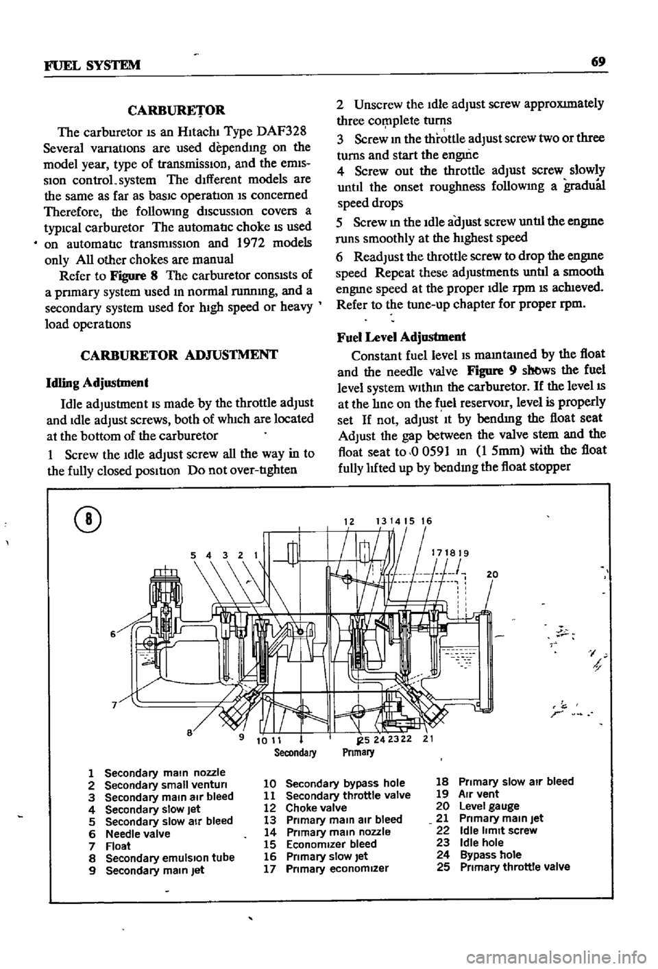
Refer
to
Figure
8
The
carburetor
conSIsts
of
a
pnmary
system
used
m
normal
runnmg
and
a
secondary
system
used
for
hIgh
speed
or
heavy
load
operatIons
CARBURETOR
ADJUSTMENT
Idling
Adjustment
Idle
adjustment
IS
made
by
the
throttle
adjust
and
Idle
adjust
screws
both
of
wh1ch
are
located
at
the
bottom
of
the
carburetor
1
Screw
the
Idle
adjust
screw
all
the
way
in
to
the
fully
closed
pOSItIon
Do
not
over
tIghten
CD
6
2
Unscrew
the
Idle
adjust
screw
approXImately
three
cor
nplete
turns
3
Screw
m
the
throttle
adjust
screw
two
or
three
turns
and
start
the
engui
e
4
Screw
out
the
throttle
adjust
screw
slowly
until
the
onset
roughness
followmg
a
gradu81
speed
drops
5
Screw
m
the
Idle
aOJust
screw
untIl
the
engme
runs
smoothly
at
the
hIghest
speed
6
Readjust
the
throttle
screw
to
drop
the
engme
speed
Repeat
these
adjustments
untIl
a
smooth
engme
speed
at
the
proper
Idle
rpm
IS
ach1eved
Refer
to
the
tune
up
chapter
for
proper
rpm
Fuel
Level
Adjustment
Constant
fuel
level
IS
mamtamed
by
the
float
and
the
needle
valve
Figure
9
sb
ws
the
fuel
level
system
wlthm
the
carburetor
If
the
level
IS
at
the
lIne
on
the
f
lel
reservOir
level
is
properly
set
If
not
adjust
It
by
bendmg
the
float
seat
Adjust
the
gap
between
the
valve
stem
and
the
float
seat
to
00591
m
1
5mm
with
the
float
fully
luted
up
by
bendmg
the
float
stopper
1213141516
20
I
h
r
1
Secondary
main
nozzle
2
Secondary
small
venturi
10
Secondary
bypass
hole
18
Primary
slow
air
bleed
3
Secondary
main
air
bleed
11
Secondary
throttle
valve
19
Air
vent
4
Secondary
slow
Jet
12
Choke
valve
20
Level
gauge
5
Secondary
slow
air
bleed
13
Primary
main
air
bleed
21
Primary
main
Jet
6
Needle
valve
14
Primary
main
nozzle
22
Idle
limit
screw
7
Float
15
Economizer
bleed
23
Idle
hole
8
Secondary
emulSion
tube
16
Primary
slow
let
24
Bypass
hole
9
Secondary
main
Jet
17
Primary
economizer
25
Primary
throttle
valve
Page 75 of 252
70
CHAPTER
SEVEN
CD
1
Float
seat
2
Roat
3
Roat
stopper
4
Needle
valve
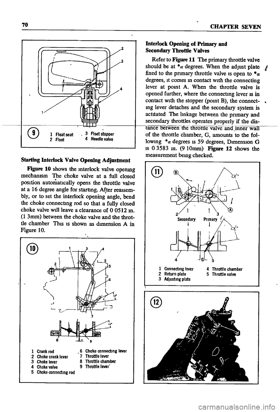
Starting
Interlock
Valve
Opening
Adjustment
Figure
10
shows
the
Interlock
valve
openmg
mechanISm
The
choke
valve
at
a
full
closed
pOSItion
automatIcally
opens
the
throttle
valve
at
a
16
degree
angle
for
startlng
ter
reassem
bly
or
to
set
the
interlock
opening
angle
bend
the
choke
connectlng
rod
so
that
a
fully
closed
choke
valve
will
leave
a
clearance
of
0
0512
m
1
3mm
between
the
choke
valve
and
the
throt
tle
chamber
ThIS
IS
shown
as
dImension
A
in
Figure
10
@
7
1
Crank
rod
6
Choke
connecting
lever
2
Choke
crank
le
er
7
Throttle
lever
3
Choke
lever
8
Throttle
chamber
4
Choke
VBI
e
9
Throttle
lever
5
Choke
connecting
rod
Interlock
Opening
of
Primary
and
Secondary
Throttle
Valves
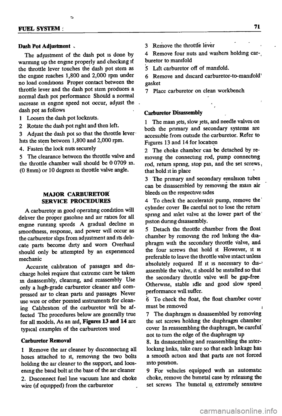
Refer
to
Figure
11
The
primary
throttle
valve
should
be
at
a
degrees
When
the
adjust
plate
I
fixed
to
the
pnmary
throttle
valve
IS
open
to
a
degrees
It
comes
In
contact
WIth
the
connecting
lever
at
pOInt
A
When
the
throttle
valve
is
opened
further
where
the
connectIng
lever
IS
in
contact
With
the
stopper
POInt
B
the
connect
mg
lever
detaches
and
the
secondary
system
is
actllated
The
lInkage
between
the
pnmary
and
secondary
throttles
operates
properly
if
the
dis
tance
6etween
theilirotlle
valve
anainner
will
of
the
throttle
chamber
G
amounts
to
the
fol
lowmg
a
degrees
IS
59
degrees
DImenSIon
G
IS
03583
In
910mm
Figure
12
shows
the
measurement
bemg
checked
@
2
Secondary
I
1
Connecting
le
er
2
Return
plate
3
Adjusting
plate
4
Throttle
chamber
5
Throttle
valve
I
1
I
r
t
i
t
r
1
I
j
I
00
I
r
@
Page 76 of 252
FUEL
SYSTEM
71
Dash
Pot
Adjustment
The
adjustment
of
the
dash
pot
IS
done
by
warmmg
up
the
engme
properly
and
checkIng
If
the
throttle
lever
touches
th
dash
pot
stem
as
the
engine
reaches
1
800
and
2
000
rpm
under
no
load
conditIons
Proper
contact
between
the
throttle
lever
and
the
dash
pot
stem
produces
a
normal
dash
pot
performance
Should
a
normal
mcrease
m
engme
speed
not
occur
adjust
the
dash
pot
as
follows
1
Loosen
the
dash
pot
locknuts
2
Rotate
the
dash
pot
nght
and
then
left
3
Adjust
the
dash
pot
so
that
the
throttle
lever
hIts
the
stem
between
1
800
and
2
000
rpm
4
Fasten
the
lock
nuts
securely
5
The
clearance
between
the
throttle
valve
and
the
throttle
chamber
wall
should
be
0
0709
m
0
8mm
or
10
degrees
In
throttle
valve
angle
MAJOR
CARBURETOR
SERVICE
PROCEDURES
A
carburetor
m
good
operatIng
condition
will
delIver
the
pr
per
gasolme
and
aIr
ratIos
for
all
engme
runnmg
speeds
A
gradual
declme
In
smoothness
response
and
power
Will
occur
as
the
carburetor
slIps
from
adjustment
and
Its
delI
cate
parts
become
dirty
and
worn
Overhaul
should
only
be
attempted
by
an
expenenced
mechanic
Accurate
calIbratIon
of
passages
and
dIS
charge
hole
reqUIre
that
extreme
care
be
taken
In
dISassembly
cleanmg
and
reassembly
Use
only
a
hIgh
grade
carburetor
cleaner
and
com
pressed
arr
to
clean
parts
and
passages
Never
use
wire
or
other
pOInted
Instruments
for
clean
ing
CalIbratIon
of
the
carburetor
will
be
af
fected
The
procedures
below
are
generally
true
for
all
models
As
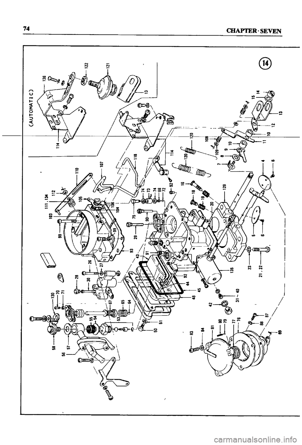
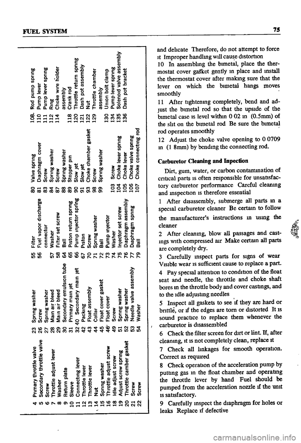
an
aId
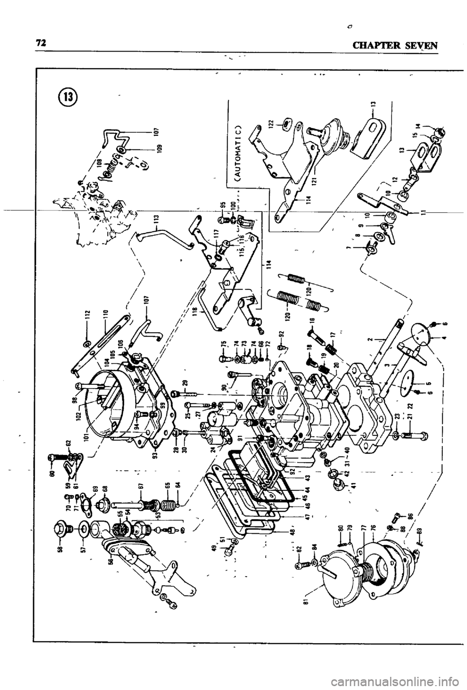
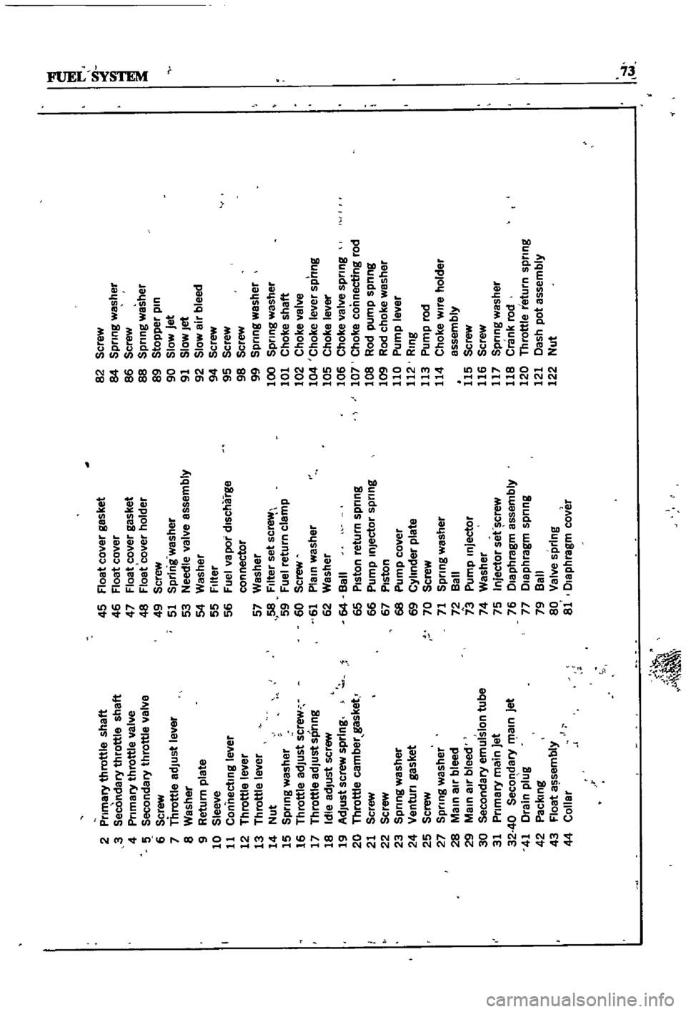
Figures
13
and
14
are
typIcal
examples
of
the
carburetors
used
Carburetor
Removal
1
Remove
the
au
cleaner
by
dIsconnectIng
all
hoses
attached
to
It
remoVmg
the
two
bolts
holdmg
the
aIr
cleaner
to
the
support
and
loos
enmg
the
band
bolt
at
the
base
of
the
aIr
cleaner
2
DIsconnect
fuellme
vacuum
Ime
and
choke
wire
u
eqUIpped
from
the
carburetor
3
Remove
the
throttle
lever
4
Remove
four
nuts
and
washers
holdmg
car
buretor
to
manIfold
5
Lift
carburetor
off
of
manuold
6
Remove
and
dIscard
carburetor
to
manuold
gasket
7
Place
carburetor
on
clean
workbench
Carburetor
Disassembly
1
The
maIn
Jets
slow
Jets
and
needle
valves
on
both
the
pnmary
and
secondary
systenIS
are
accessIble
from
outsIde
the
carburetor
Refer
to
FIgures
13
and
14
for
locatI
n
2
The
choke
chamber
can
be
detached
by
re
mOVIng
the
connectIng
rod
pump
connectIng
rod
return
sprmg
stop
pm
and
the
set
screws
I
that
hold
It
in
place
3
The
pnmary
and
secondary
emulSIon
tubes
can
be
disassembled
by
remOVIng
the
mam
air
bleeds
on
the
respectIve
SIdes
4
To
check
the
accelerator
pump
remove
the
cylInder
cover
Be
careful
not
to
lose
the
return
spnng
and
Inlet
valve
at
the
lower
part
of
the
pIston
durmg
dIsassembly
5
Detach
the
throttle
chamber
from
the
float
chamber
by
remOVIng
the
rod
lInkIng
the
dia
phragm
WIth
the
secondary
throttle
valve
and
the
four
screws
that
hold
It
However
It
IS
preferable
to
leave
the
throttle
valve
mtact
unless
absolutely
reqUired
If
It
IS
necessary
to
dlS
assemble
the
valve
It
should
be
Installed
so
that
the
secondary
throttle
valve
will
be
gap
free
OtherwIse
stable
Idle
and
good
slow
speed
performance
will
suffer
is
To
check
the
float
the
float
chamber
cover
must
be
removed
I
7
The
dIaphragm
IS
dIsassembled
by
removing
the
set
screws
holdmg
the
dIaphragm
chamber
cover
In
reassemblIng
the
diaphragm
be
careful
not
to
turn
the
edge
of
the
dIaphragm
up
8
In
dlsassemblmg
and
reassembling
the
mter
lockIng
lInks
take
care
so
that
each
lInkage
has
a
smooth
actIon
and
that
parts
are
not
forced
mto
pOSItIon
9
For
vehIcles
equipped
With
an
automatIc
choke
remove
the
brmetal
case
by
releasmg
the
set
screws
The
bimetal
1l
extremely
senSItIve
Page 77 of 252
a
C1
1AyTEll
Sy
VEN
@
t
i
o
j
J
1
I
cP
C
O
c
o
I
I
4
J
Page 78 of 252
j
2
Primary
throttle
shaft
45
Float
cover
gasket
82
Screw
I
f
l
3
Secondary
throttle
shaft
46
Float
cover
84
Spring
washer
4
Primary
throttle
valve
47
Float
cover
gasket
86
Screw
5
Secondary
throttle
valve
48
Float
cover
holder
88
Spring
washer
6
Screw
49
Screw
89
Stopper
pin
7
Throttle
adJust
lever
51
Sprln
g
washer
90
Slow
Jet
8
Washer
53
Needle
valve
assembly
91
Slow
Jet
9
Return
plate
54
Washer
92
Slow
air
bleed
10
Sleeve
55
Filter
94
Screw
11
Connecting
lever
56
Fuel
va
por
discharge
95
Screw
12
Throttle
lever
con
nectar
98
Screw
13
Throttle
lever
57
Washer
99
Spring
washer
14
Nut
58
Filter
set
sc
100
Spring
washer
15
Spring
washer
59
Fuel
return
clamp
101
Choke
shaft
16
Throttle
adJust
screw
60
Screw
102
Choke
valve
17
Throttle
adJUst
spring
61
Plain
washer
104
Choke
lever
spong
18
Idle
adJust
screw
62
Washer
105
Choke
lever
19
AdJust
screw
spring
64
Ball
106
Choke
valve
spring
20
Throttle
camber
gasket
65
Piston
return
spring
107
Choke
connecting
rod
21
Screw
66
Pump
inJector
spring
108
Rod
pump
spnng
22
Screw
67
Piston
109
Rod
choke
washer
23
Spring
washer
68
Pump
cover
110
Pump
lever
24
Venturi
gasket
69
Cylinder
plate
112
Ring
25
Screw
70
Screw
113
Pump
rod
27
Spring
washer
71
Spring
washer
114
Choke
wire
holder
28
Main
air
bleed
72
Ball
assembly
29
Main
aIr
bleed
73
Pump
Injector
115
Screw
30
Secondary
emulsion
tube
74
Washer
116
Screw
31
Primary
main
jet
75
Injector
set
crew
117
Spring
washer
32
40
Secondary
R
1aln
jet
76
Diaphragm
assembly
118
Crank
rod
41
Drain
plug
77
Diaphragm
spring
120
Throttle
return
spring
42
Packing
79
Ball
121
Dash
pot
assembly
43
Float
assembly
80
Valve
spring
122
Nut
44
Collar
81
Diaphragm
cover
I
I
4
6
Page 79 of 252
@
Page 80 of 252
FUEL
SYSTEM
75
s
E
u
m
c
DO
2
t
Eo
c
E
D
EEm
0
0
G
E
cac
cvu
cn
J
co
ucn
e
a
CVQ
CD
Q
c
E
C
u
0
J
oeQ
O
G
O
cQ
O
E
E
EE
g
0
E
E
Q
II
2
en
e
GJ
9
E
en
J
J
s
eJ
ctI
J
c
l
Joca
OmO
CZ
m
C
mO
NV
O
Nm
O
01
1
P
IC
lC
lC
lN
f
rr
r
tr
P
t
I
I
I
I
I
l
m
u
m
bOt
J
oCc
E
E
E
co
en
bel
3
J
ca
e
tt
tlu
3
j
31b031
31
c
G
Q
a
3
3
cuE
ca
0
0
0
0
O
Q
C
u
c3
0
I
q
COO
Ol
t
l
Q
O
ClOClOClOClOClOClOClOOlOlOlOlOl
2
DO
tlD
2
E
E
tl
cog
u
I
j
0
000
u
c
s
c
c
oooo
l
v
t
D
00000
tlD
tlD
3
f
c
0
CD
S
U
o
c
u
0
en
Q
en
Q
t
ee
o
B
c
e
cnbObO
ca
u
ca
ca
ga
C3
c
G
ccn2
ESft
EcnG
a
a
Joca
ca
J
ua
m
Jca
ca
u
ClO
ClO
CCClO
m
j
u
s
u
m
a
is
g
t
ii
E
l
1
b
en
1
t
t
iEc
c
m
cvCVQ
ccvcvCV
ca
E
co
C
C
E
caca
31
3l
m
ODO
00
3131
bel
bOcaca
caucca
UU
bO
CV
c3
cccoE
m
C
c
C
c
b
im
t
g
O
O
Z
d
M
ClOOlO
NNM
d
Ol
NM
d
NNNNNMMM
d
cvm
3
bO
u
5
cn
o
o
E
t
j
I
cn
c
z
lD
c
cn
tE
c
C
bOQ
Q
cn
C
ca
L
CQ
c
mCQcnuu
CQ
C1
Q
eC1
C1
C1
cnC1
i
E
EE
E
E
E
E
8
f
e
cn
a
c
e
e
i
e
Q
e
w8
z
d
ClOOlO
NM
ClOOlO
N
1
11
1
I
1
1
l
l
l
l
l
l
lC
lC
lC
l
and
delIcate
Therefore
do
not
attempt
to
force
It
Improper
handlmg
WIll
cau
e
dIstortIOn
10
In
assemblIng
the
bImetal
place
the
ther
mostat
cover
gaSket
gently
In
place
and
mstall
the
thermostat
cover
after
makmg
sure
that
the
lever
on
which
the
bImetal
hangs
moves
smoothly
11
After
ughtenmg
completely
bend
and
ad
Just
the
bImetal
rod
so
that
the
upSIde
of
the
bImetal
case
IS
level
withm
0
02
m
O
5mm
of
the
slIt
on
the
bImetal
rod
Be
sure
the
bImetal
rod
operates
smoothly
12
Adjust
the
choke
valve
opening
to
00709
m
1
8mm
by
bendIng
the
connecting
rod
Carburetor
Cleaning
and
Inpection
Dirt
gum
water
or
carbon
contammation
of
cntIcal
parts
IS
often
responsIble
for
unsatlsfac
tory
carburetor
performance
Careful
cleanmg
and
InspectIon
IS
therefore
essential
1
After
disassembly
submerge
all
parts
In
a
specIal
carburetor
cleaner
Be
certam
to
follow
the
mmufacrurer
s
instructions
In
usmg
the
cleaner
2
After
cleanmg
blow
all
passages
and
cast
mgs
With
compressed
aIr
Make
certam
all
parts
are
completely
dry
3
Carefully
mspect
parts
for
SIgnS
of
wear
VISIble
wear
IS
suffiCIent
cause
to
replace
a
part
4
Pay
speCIal
attentIon
to
condItIon
of
the
float
seat
and
needle
the
throttle
and
choke
shaft
bores
In
the
throttle
body
and
cover
castIngs
and
to
the
Idle
adjustIng
needles
5
Inspect
all
gaskets
to
see
IT
they
are
hard
or
bnttle
or
IT
the
edges
are
tom
or
dIstorted
It
IS
sound
practIce
to
replace
them
whenever
the
carburetor
is
dIsassembled
6
Check
the
filter
screen
for
dIrt
or
lint
If
after
cleanmg
It
IS
not
completely
clean
replace
It
7
Check
all
lInkages
for
smooth
operatIon
Correct
as
reqUIred
8
Check
operation
of
the
acceleration
pump
by
puttIng
gas
m
the
float
chamber
and
operatIng
the
throttle
lever
by
hand
Fuel
should
be
pumped
from
the
acceleration
nozzle
IT
the
unIt
IS
satlsfactory
9
Carefully
InSpect
the
dIaphragm
for
holes
or
leaks
Replace
IT
defective
il