DATSUN 510 1968 Service Repair Manual
Manufacturer: DATSUN, Model Year: 1968, Model line: 510, Model: DATSUN 510 1968Pages: 252, PDF Size: 12.2 MB
Page 101 of 252
96
CHAFTER
NINE
@
EK
lle
Correct
Incorrect
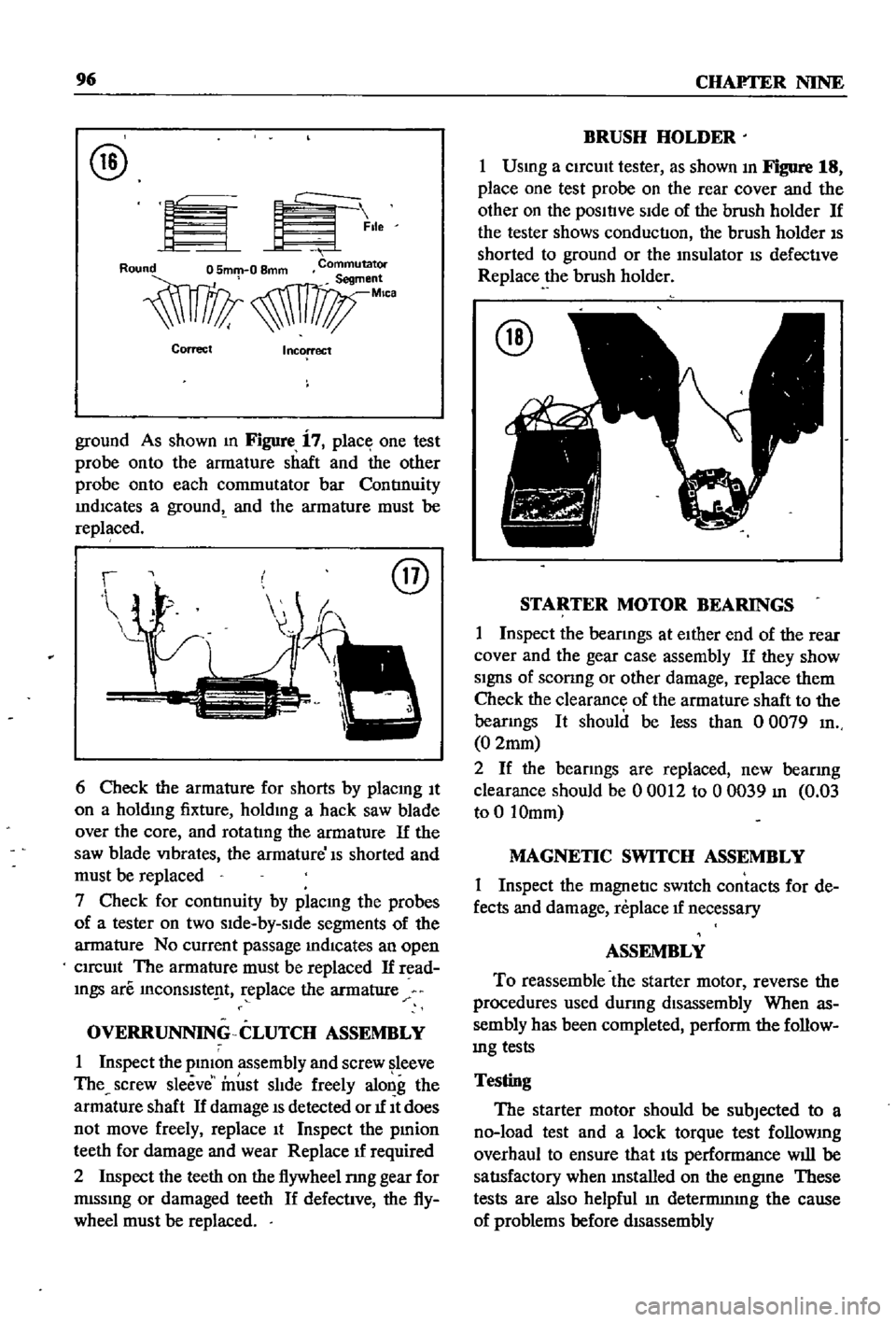
ground
As
shown
m
Figure
i
7
place
one
test
probe
onto
the
armature
shaft
and
the
other
probe
onto
each
commutator
bar
ContInuity
IndICates
a
groundt
and
the
armature
must
be
replaced
@
6
Check
the
armature
for
shorts
by
placmg
It
on
a
holdmg
fixture
holdmg
a
hack
saw
blade
over
the
core
and
rotatIng
the
armature
If
the
saw
blade
VIbrates
the
armature
Is
shorted
and
must
be
replaced
7
Check
for
contInuity
by
placmg
the
probes
of
a
tester
on
two
sIde
by
slde
segments
of
the
armature
No
current
passage
mdlcates
an
open
CIrcUIt
The
armature
must
be
replaced
If
read
mgs
are
InCOnslste
t
replace
the
armature
OVERRUNNING
CLUTCH
ASSEMBLY
1
Inspect
the
plmon
assembly
and
screw
leeve
The
screw
sleeve
must
slIde
freely
along
the
armature
shaft
If
damage
IS
detected
or
1f
It
does
not
move
freely
replace
It
Inspect
the
pmion
teeth
for
damage
and
wear
Replace
1f
required
2
Inspect
the
teeth
on
the
flywheel
nng
gear
for
mlssmg
or
damaged
teeth
If
defective
the
fly
wheel
must
be
replaced
BRUSH
HOLDER
1
Usmg
a
CirCUIt
tester
as
shown
In
Figure
18
place
one
test
probe
on
the
rear
cover
and
the
other
on
the
posltlve
SIde
of
the
brush
holder
If
the
tester
shows
conduction
the
brush
holder
IS
shorted
to
ground
or
the
msulator
IS
defective
Replace
the
brush
holder
@
STARTER
MOTOR
BEARINGS
1
Inspect
the
bearmgs
at
eIther
end
of
the
rear
cover
and
the
gear
case
assembly
If
they
show
SignS
of
sconng
or
other
damage
replace
them
Check
the
clearance
of
the
armature
shaft
to
the
bearmgs
It
should
be
less
than
0
0079
In
0
2mm
2
If
the
bearings
are
replaced
new
bearing
clearance
should
be
00012
to
00039
In
0
03
to
0
10mm
MAGNETIC
SWITCH
ASSEMBLY
1
Inspect
the
magnetic
sWItch
contacts
for
de
fects
and
damage
replace
1f
necessary
ASSEMBLY
To
reassemble
the
starter
motor
reverse
the
procedures
used
dUring
disassembly
When
as
sembly
has
been
completed
perform
the
follow
mg
tests
Testing
The
starter
motor
should
be
subjected
to
a
no
load
test
and
a
lock
torque
test
follOWIng
overhaul
to
ensure
that
Its
performance
will
be
satIsfactory
when
mstalled
on
the
engme
These
tests
are
also
helpful
In
detennmIng
the
cause
of
problems
before
dIsassembly
Page 102 of 252
ENGINE
ELECI
RlCAL
SYSTEM
97
No
Load
Lock
Torque
Test
1
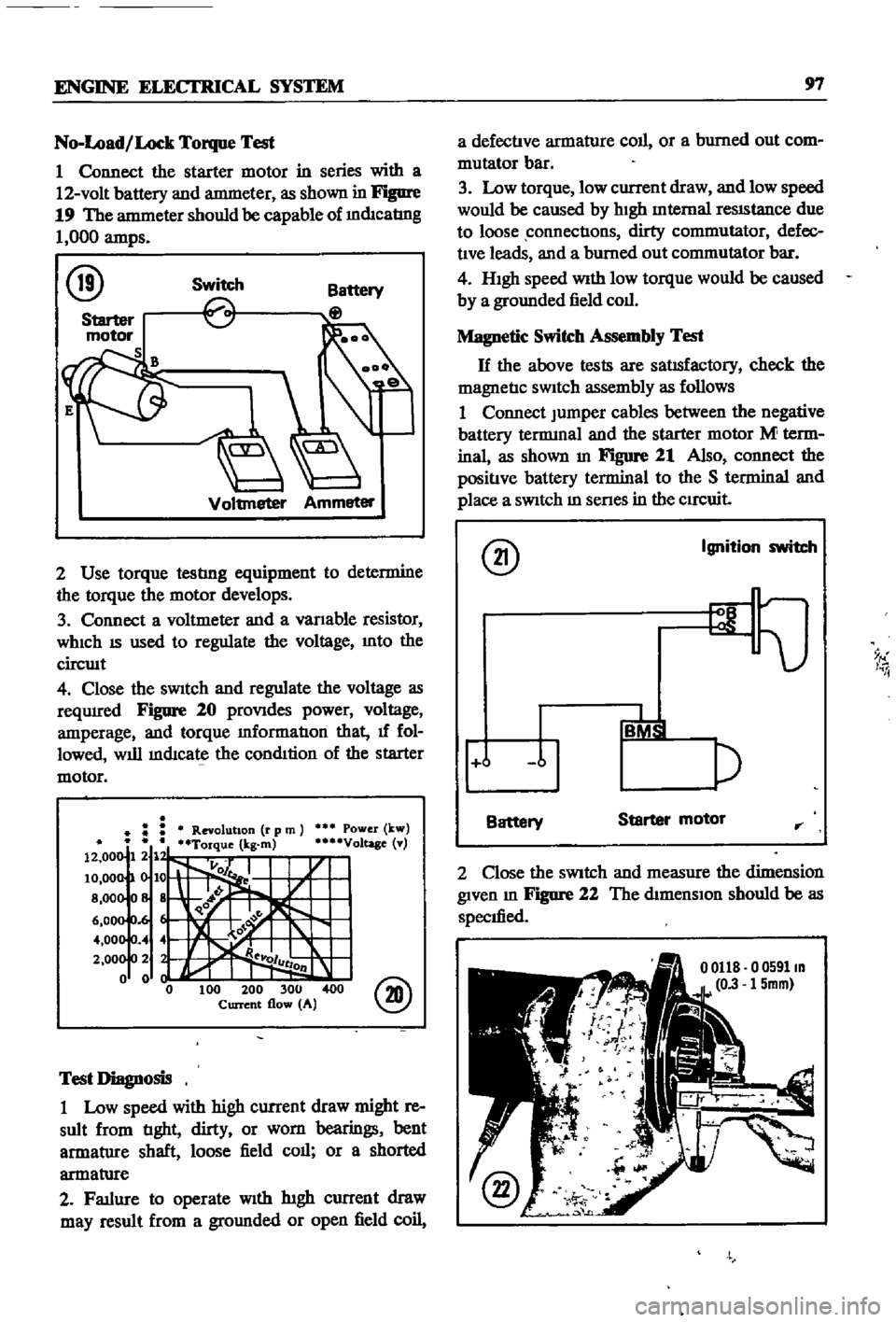
Connect
the
starter
motor
in
series
with
a
12
volt
battery
and
antmeter
as
shown
in
Figure
19
The
antmeter
should
be
capable
of
mdIcatIng
1
000
amps
@
Switch
Voltmeter
Ammeter
2
Use
torque
testlng
equipment
to
determine
the
torque
the
motor
develops
3
Connect
a
voltmeter
and
a
vanable
resistor
WhICh
IS
used
to
regulate
the
voltage
Into
the
circwt
4
Close
the
sWitch
and
regulate
the
voltage
as
reqUIred
Figure
20
proVIdes
power
voltage
amperage
and
torque
mformatIon
that
1f
fol
lowed
will
mdIcate
the
condItion
of
the
starter
motor
Power
kw
Voltage
v
@
Test
Diagnosis
1
Low
speed
with
high
current
draw
might
re
sult
from
tIght
dirty
or
worn
bearings
bent
armatlIre
shaft
loose
field
call
or
a
shorted
armatlIre
2
Fatlure
to
operate
With
htgh
current
draw
may
result
from
a
gromlded
or
open
field
coil
a
defectIve
armature
coll
or
a
burned
out
com
mutator
bar
3
Low
torque
low
current
draw
and
low
speed
would
be
caused
by
hIgh
Internal
reSIStance
due
to
loose
connectIons
dirty
commutator
defec
tIve
leads
and
a
burned
out
commutator
bar
4
HIgh
speed
With
low
torque
would
be
caused
by
a
grounded
field
coll
Magnetic
Switch
Assembly
Test
H
the
above
tests
are
satIsfactory
check
the
magnetIc
SWitch
assembly
as
follows
1
Connect
Jumper
cables
between
the
negative
battery
tennmal
and
the
starter
motor
M
term
inal
as
shown
In
Figure
21
Also
connect
the
positIve
battery
terminal
to
the
S
terminal
and
place
a
SWitch
m
senes
in
the
CIrCuit
@
Ignition
switch
9
I
i
j
Battery
Starter
motor
rr
2
Close
the
SWitch
and
measure
the
dimension
given
m
Figure
22
The
dimensIon
should
be
as
specIfied
o
0591m
15mm
Page 103 of 252
98
CHAPTER
NINE
CHARGING
CIRCUIT
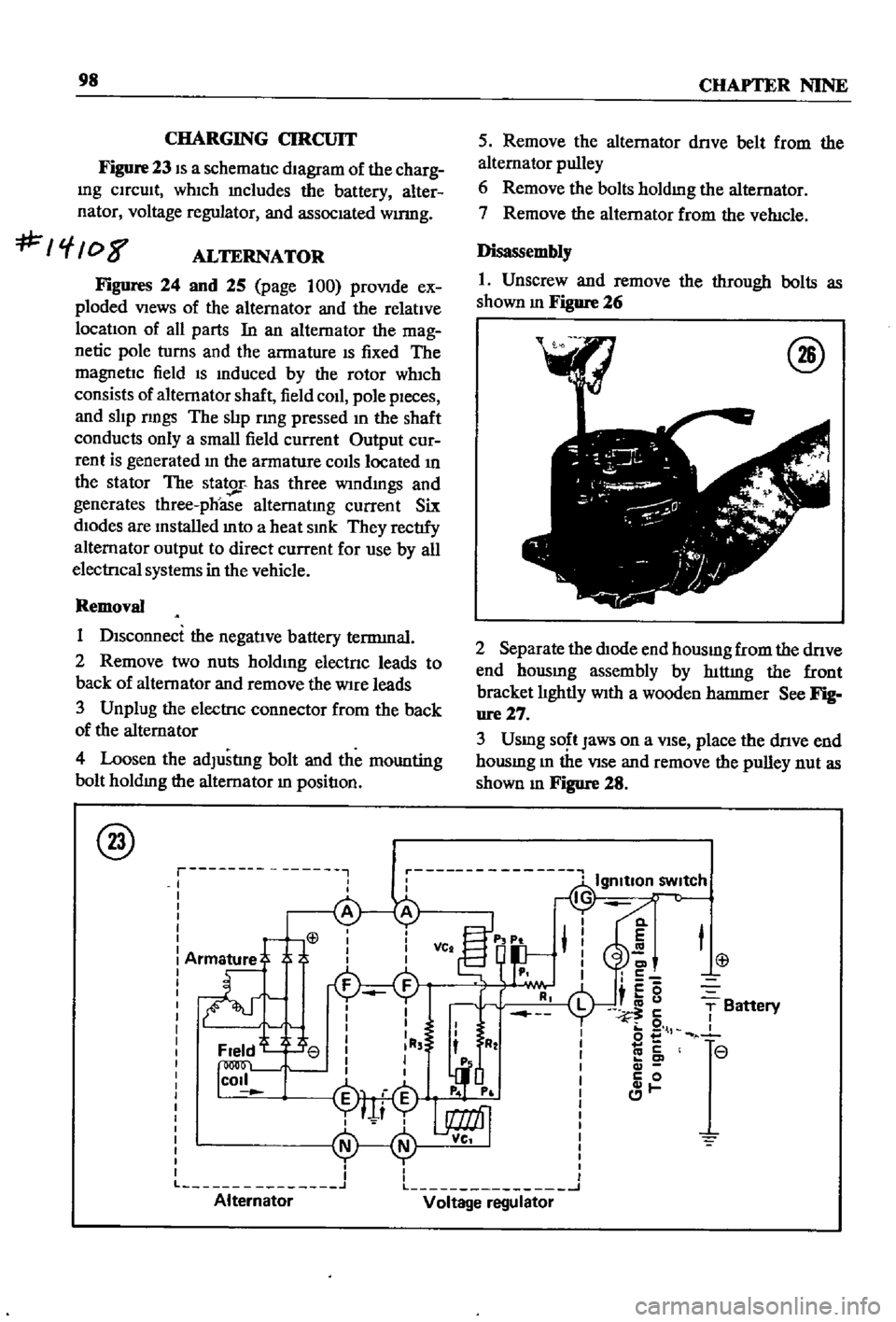
Figure
23
IS
a
schematIc
dIagram
of
the
charg
Ing
CIrcuIt
whIch
mcludes
the
battery
alter
nator
voltage
regulator
and
assocIated
wumg
f
08
ALTERNATOR
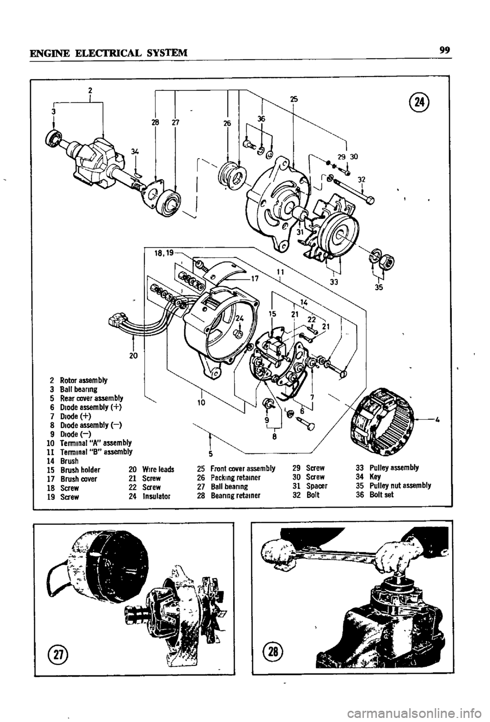
Figures
24
and
25
page
100
proVIde
ex
ploded
VIews
of
the
alternator
and
the
relatIve
locatIon
of
all
parts
In
an
alternator
the
mag
netic
pole
turns
and
the
armature
IS
fixed
The
magnetIc
field
IS
Induced
by
the
rotor
wh1ch
consists
of
alternator
shaft
field
coIl
pole
pIeces
and
slIp
nngs
The
slIp
rmg
pressed
In
the
shaft
conducts
only
a
small
field
current
Output
cur
rent
is
generated
In
the
armature
COIls
located
In
the
stator
The
stator
has
three
wIndmgs
and
generates
three
phoase
alternatIng
current
Six
dIodes
are
Installed
mto
a
heat
SInk
They
rectIfy
alternator
output
to
direct
current
for
use
by
all
electrIcal
systems
in
the
vehicle
Removal
1
DIsconnect
the
negatIve
battery
terrmnal
2
Remove
two
nuts
holdIng
electnc
leads
to
back
of
alternator
and
remove
the
Wire
leads
3
Unplug
the
electrIc
connector
from
the
back
of
the
alternator
4
Loosen
the
adJustlng
bolt
and
the
mounting
bolt
holdIng
the
alternator
In
positIon
@
r
I
I
I
L
Alternator
5
Remove
the
alternator
dnve
belt
from
the
alternator
pulley
6
Remove
the
bolts
holdmg
the
alternator
7
Remove
the
alternator
from
the
veh1cle
Disassembly
1
Unscrew
and
remove
the
through
bolts
as
shown
m
Figure
26
@
2
Separate
the
dIOde
end
housmg
from
the
dnve
end
hOUSIng
assembly
by
hlttmg
the
front
bracket
lIghtly
WIth
a
wooden
hatnnler
See
Fig
ure27
3
Usmg
SO
t
Jaws
on
a
VIse
place
the
dnve
end
housmg
m
the
VIse
and
remove
the
pulley
nut
as
shown
m
Figure
28
Cl
E
C
c5
i
u
5
o
l
co
c
c
0
1
T
Battery
r
r
L
J
Voltage
regulator
Page 104 of 252
ENGINE
ELECfRlCAL
SYSTEM
99
2
3
r
I
J
20
2
Rotor
aS5em
bly
3
Ball
beanng
5
Rear
cover
assembly
6
Diode
assembly
7
Diode
8
Diode
assembly
9
Diode
10
Terminal
A
assembly
11
Terminal
B
assembly
14
Brush
15
Brush
holder
17
Brush
co
er
18
Screw
19
Sa
ew
@
8
Front
cover
assembly
Packing
retainer
Ball
beanng
Beanng
retainer
29
Screw
30
Screw
31
Spacer
32
Bolt
33
Pulley
assembly
34
Key
35
Pulley
nut
assembly
36
Bolt
set
20
Wire
leads
21
Screw
22
Screw
24
Insulator
@
@
Page 105 of 252
100
CHAPTER
NINE
@
1
1
43
44
45
46
49
I
tYV
48
47
37
Alternator
bracket
38
Hex
bolt
39
Hex
bolt
40
lock
spnng
washer
41
8racket
shim
42
AdJusltng
bar
43
Hex
bolt
4
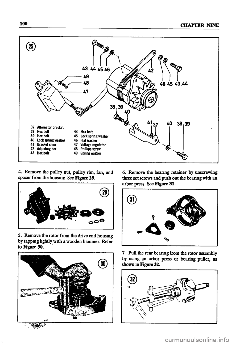
Remove
the
pulley
nut
pulley
rim
fan
and
spacer
from
the
hOUSIng
See
Figure
29
@
000
5
Remove
the
rotor
from
the
drive
end
housmg
by
tappIng
lIghtly
With
a
wooden
hammer
Refer
to
Figure
30
@
1
46
45
43
44
38
39
6
Remove
the
beanng
retainer
by
unscrewing
three
set
screws
and
push
out
the
bearmg
with
an
arbor
press
See
Figure
31
@
A
t
J
r
j
f
1
p
O
7
Pull
the
rear
bearmg
from
the
rotor
assembly
by
usmg
an
arbor
press
or
bearing
puller
as
shown
m
Figure
32
@
Page 106 of 252
ENGINE
ELECTRICAL
SYSTEM
101
8
To
separate
the
stator
from
the
dIode
end
housmg
assembly
unsolder
the
three
negatIve
dIodes
from
the
three
co1l1ead
WIres
The
nega
tIve
dIodes
are
marked
WIth
black
figures
and
the
posItIve
ones
With
red
figures
CAUTION
Use
extreme
care
when
unsoldenng
the
diodes
to
prevent
excessive
heat
from
damagmg
thi
m
Use
a
100
to
200
watt
soldermg
Iron
for
no
more
than
two
seconds
at
the
dIOde
Junction
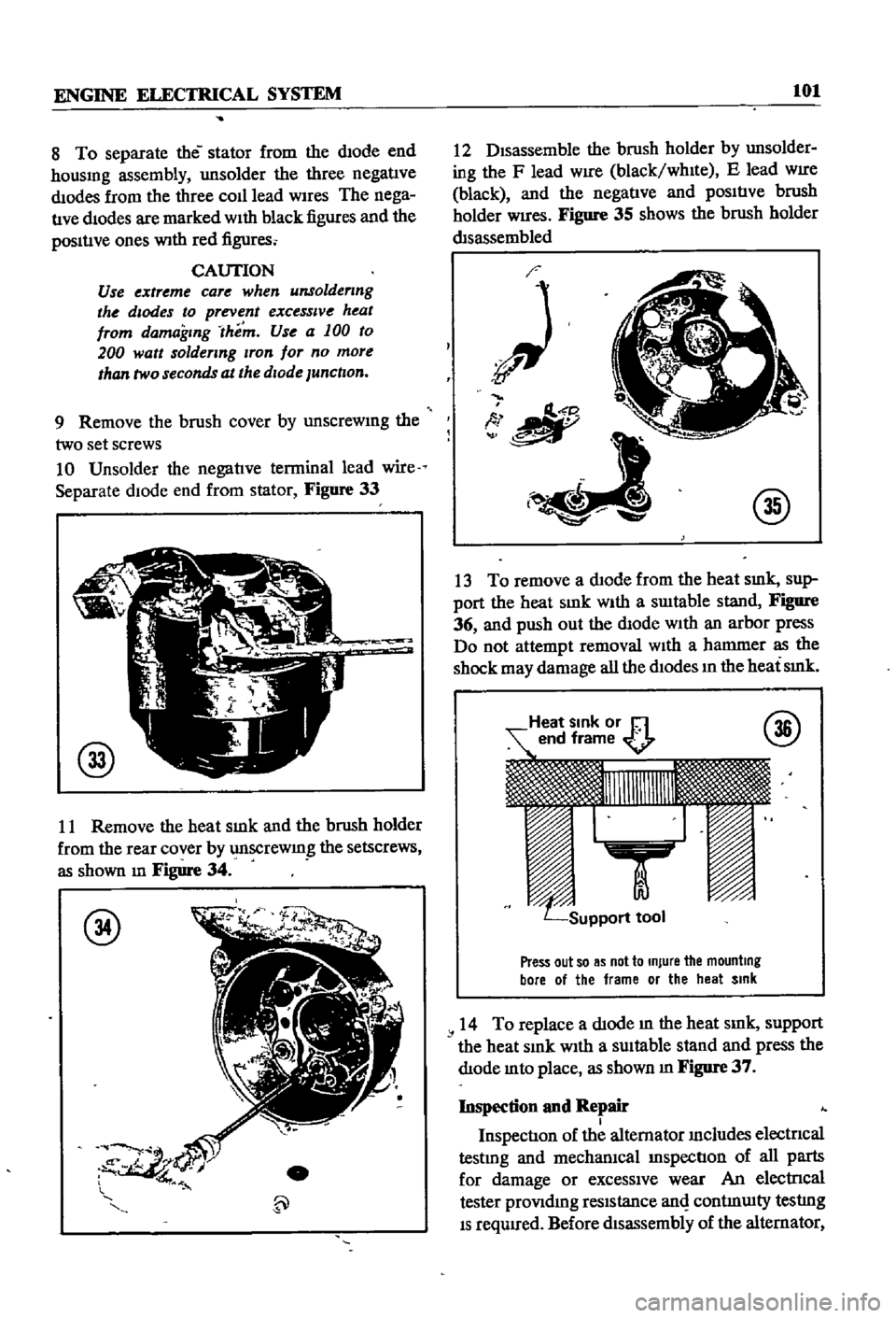
9
Remove
the
brush
cover
by
unscreWIng
the
two
set
screws
10
Unsolder
the
negatIve
terminal
lead
wire
Separate
dIOde
end
from
stator
Figure
33
@
11
Remove
the
heat
smk
and
the
brush
holder
from
the
rear
cover
by
unscrewmg
the
setscrews
as
shown
m
Figure
34
@
12
DIsassemble
the
brush
holder
by
unsolder
ing
the
F
lead
WIre
black
whIte
E
lead
WIre
black
and
the
negatIve
and
pOSItIve
brush
holder
Wires
Figure
35
shows
the
brush
holder
dIsassembled
O
tlII
I
@
13
To
remove
a
dIode
from
the
heat
smk
sup
port
the
heat
SInk
WIth
a
swtable
stand
Figure
36
and
push
out
the
dIode
With
an
arbor
press
Do
not
attempt
removal
WIth
a
hammer
as
the
shock
may
damage
all
the
dIodes
ill
the
heat
SInk
Press
out
so
as
not
to
Injure
the
mounting
bore
01
the
frame
or
the
heat
Sink
14
To
replace
a
dIode
m
the
heat
smk
support
the
heat
SInk
With
a
SUItable
stand
and
press
the
dIode
mto
place
as
shown
m
Figure
37
Inspection
and
Repair
I
InspectIon
of
the
alternator
Includes
electncal
testmg
and
mechanIcal
InspectIon
of
all
parts
for
damage
or
exceSSIve
wear
An
electrIcal
tester
proVIdmg
reSIstance
anI
contmUlty
testlng
IS
requIred
Before
dIsassembly
of
the
alternator
Page 107 of 252
102
CHAPTER
NINE
@
I
lc@
it
should
be
tested
by
connectlng
the
probes
of
the
tester
t9
the
F
lead
WIre
blackfwmte
and
the
E
lead
wire
black
The
resistance
should
read
between
5
and
6
ohms
If
the
resIStance
is
incorrect
the
alternator
must
be
disassembled
and
tested
further
as
descnbed
below
ROTOR
INSPECTION
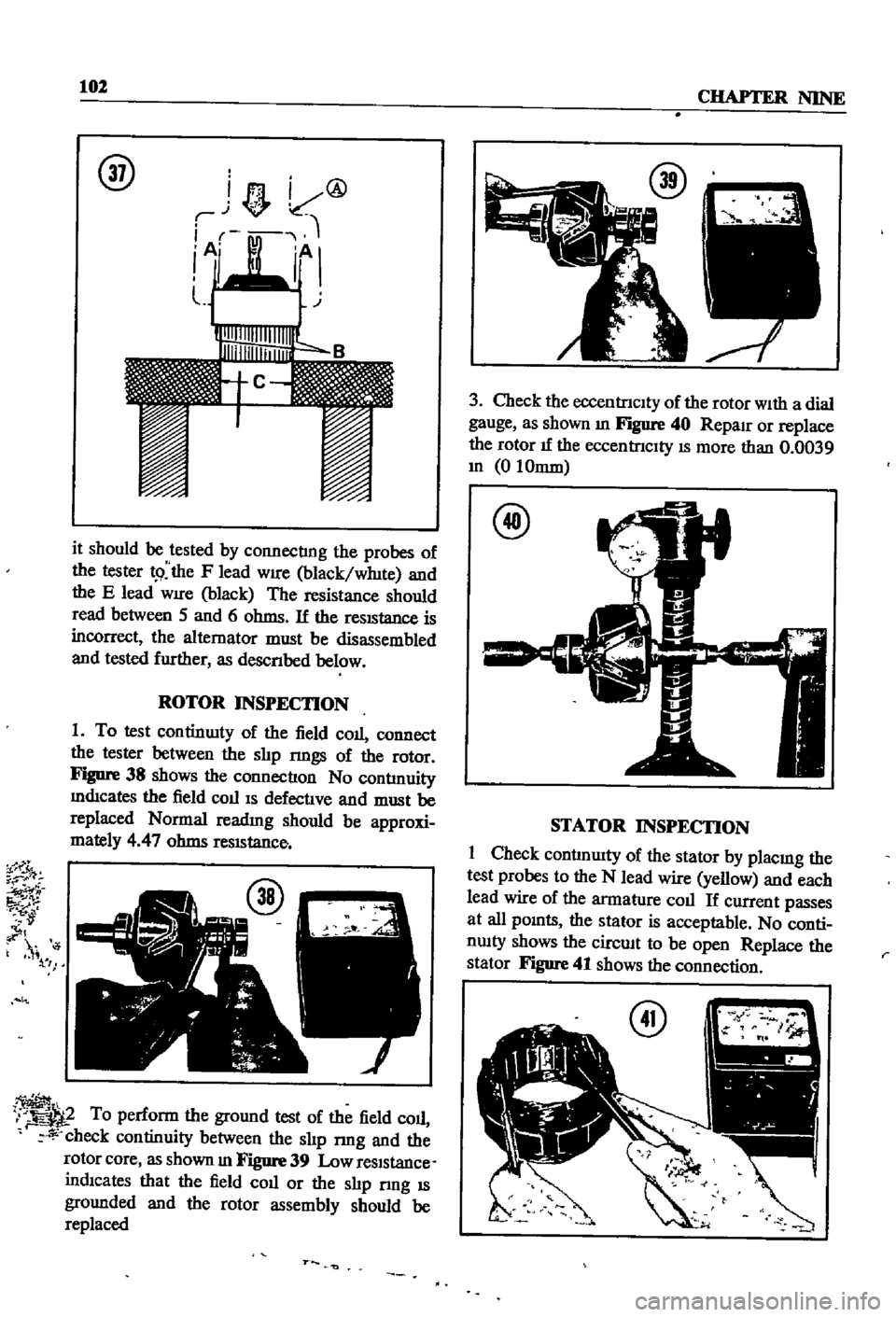
1
To
test
continwty
of
the
field
coll
connect
the
tester
between
the
shp
rmgs
of
the
rotor
Figure
38
shows
the
connectIon
No
contlnuity
mdIcates
the
field
COllIS
defectIve
and
must
be
replaced
Normal
readmg
should
be
approxi
mately
4
47
ohms
reSIStance
i
1
I
To
perform
the
ground
test
of
the
field
coll
r
check
continuity
between
the
shp
nng
and
the
rotor
core
as
shown
In
Figure
39
Low
reSIStance
indIcates
that
the
field
coll
or
the
slIp
nng
IS
grounded
and
the
rotor
assembly
should
be
replaced
r
3
Check
the
eccentrIcIty
of
the
rotor
With
a
dial
gauge
as
shown
In
Figure
40
Reparr
or
replace
the
rotor
IT
the
eccentrICIty
IS
more
than
0
0039
In
0
10mm
@
STATOR
INSPECTION
1
Check
contlnwty
of
the
stator
by
placmg
the
test
probes
to
the
N
lead
wire
yellow
and
each
lead
wire
of
the
armatl1re
coll
If
current
passes
at
all
pOlOts
the
stator
is
acceptable
No
conti
nwty
shows
the
circwt
to
be
open
Replace
the
stator
Figure
41
shows
the
connection
r
Page 108 of 252
ENGINE
ELECTRICAL
SYSTEM
103
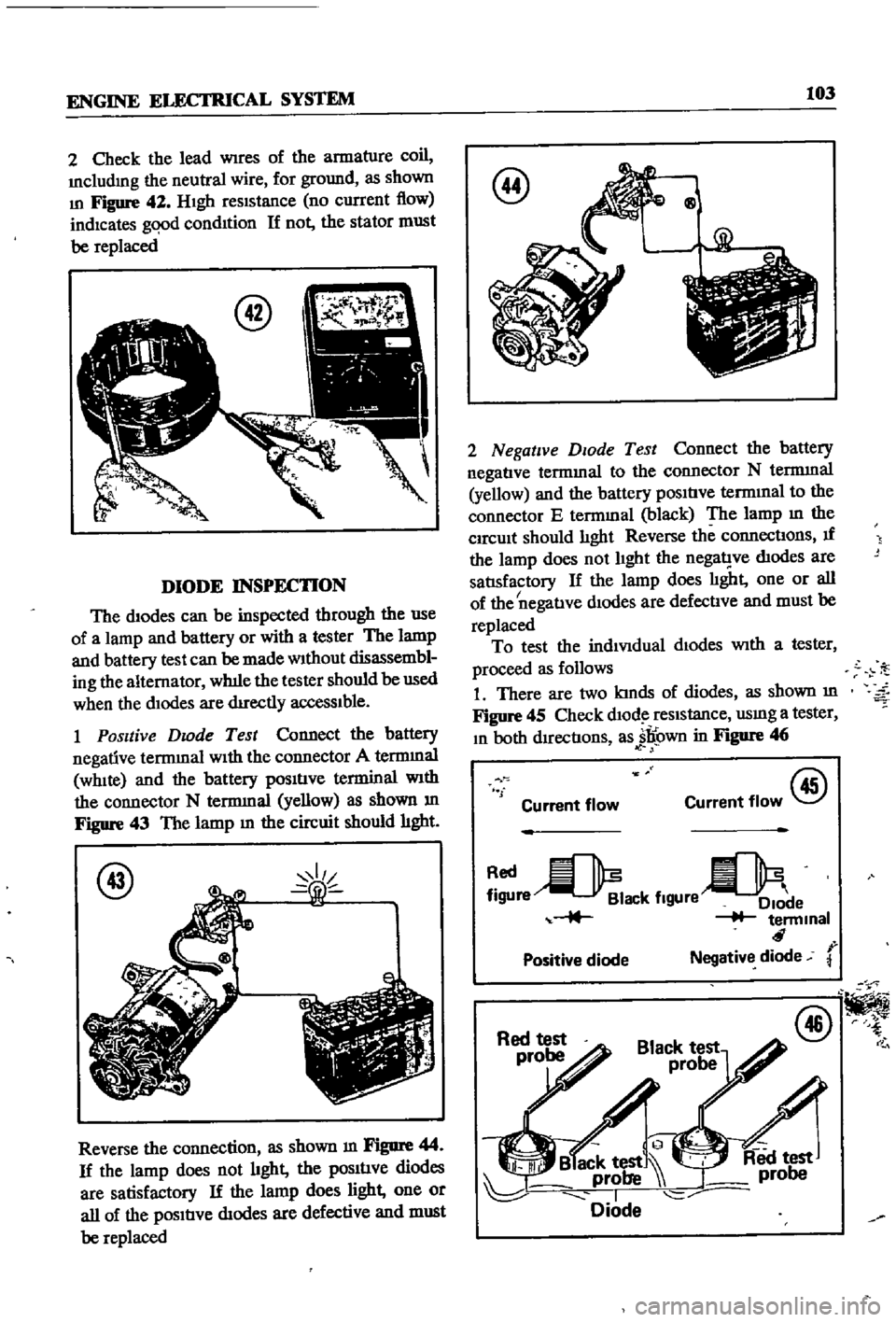
2
Check
the
lead
Wires
of
the
armature
coil
Includmg
the
neutral
wire
for
ground
as
shown
In
Figure
42
HIgh
reSIStance
no
current
flow
indicates
gqod
condItion
If
not
the
stator
must
be
replaced
DIODE
INSPECTION
The
diodes
can
be
inspected
through
the
use
of
a
lamp
and
battery
or
with
a
tester
The
lamp
and
battery
test
can
be
made
Without
disassembl
ing
the
alternator
wh1le
the
tester
should
be
used
when
the
dIodes
are
dIrectly
acceSSIble
1
Positive
Dwde
Test
Connect
the
battery
negative
terrmnal
WIth
the
connector
A
terrmnal
WhIte
and
the
battery
pOSItIve
terminal
With
the
connector
N
terrmnal
yellow
as
shown
m
Figure
43
The
lamp
m
the
circuit
should
hght
@
Reverse
the
connection
as
shown
m
Figure
44
If
the
lamp
does
not
hght
the
pOSItIve
diodes
are
satisfactory
If
the
lamp
does
light
one
or
all
of
the
pOSItIve
dIodes
are
defective
and
must
be
replaced
@
Qg
2
Negative
DIOde
Test
Connect
the
battery
negatIve
termmal
to
the
connector
N
terrmnal
yellow
and
the
battery
pOSItIve
termInal
to
the
connector
E
termmal
black
The
lamp
m
the
CIrcUit
should
lIght
Reverse
the
connectIons
If
the
lamp
does
not
lIght
the
nega1
ve
dIodes
are
satlsfactory
If
the
lamp
does
lIght
one
or
all
I
of
the
negatIve
dIodes
are
defectIve
and
must
be
replaced
To
test
the
indiVIdual
dIodes
With
a
tester
proceed
as
follows
1
There
are
two
kInds
of
diodes
as
shown
m
Figure
45
Check
dlOd
reSIstance
usmg
a
tester
In
both
dIrectIons
as
jl
own
in
Figure
46
f
Current
flow
@
Current
flow
re
ack
flgUre
e
terminal
r
Positive
diode
Negative
diode
@
Page 109 of 252
104
CHAPTER
NINE
2
When
one
sIde
shows
low
resIstance
and
the
other
shows
high
resIstance
the
dIode
IS
satls
factory
If
both
sIdes
are
low
there
IS
a
short
CIrCUIt
If
both
sIdes
are
hIgh
there
IS
an
open
CIrcUIt
All
diodes
With
open
or
short
ClrC
ts
must
be
replaced
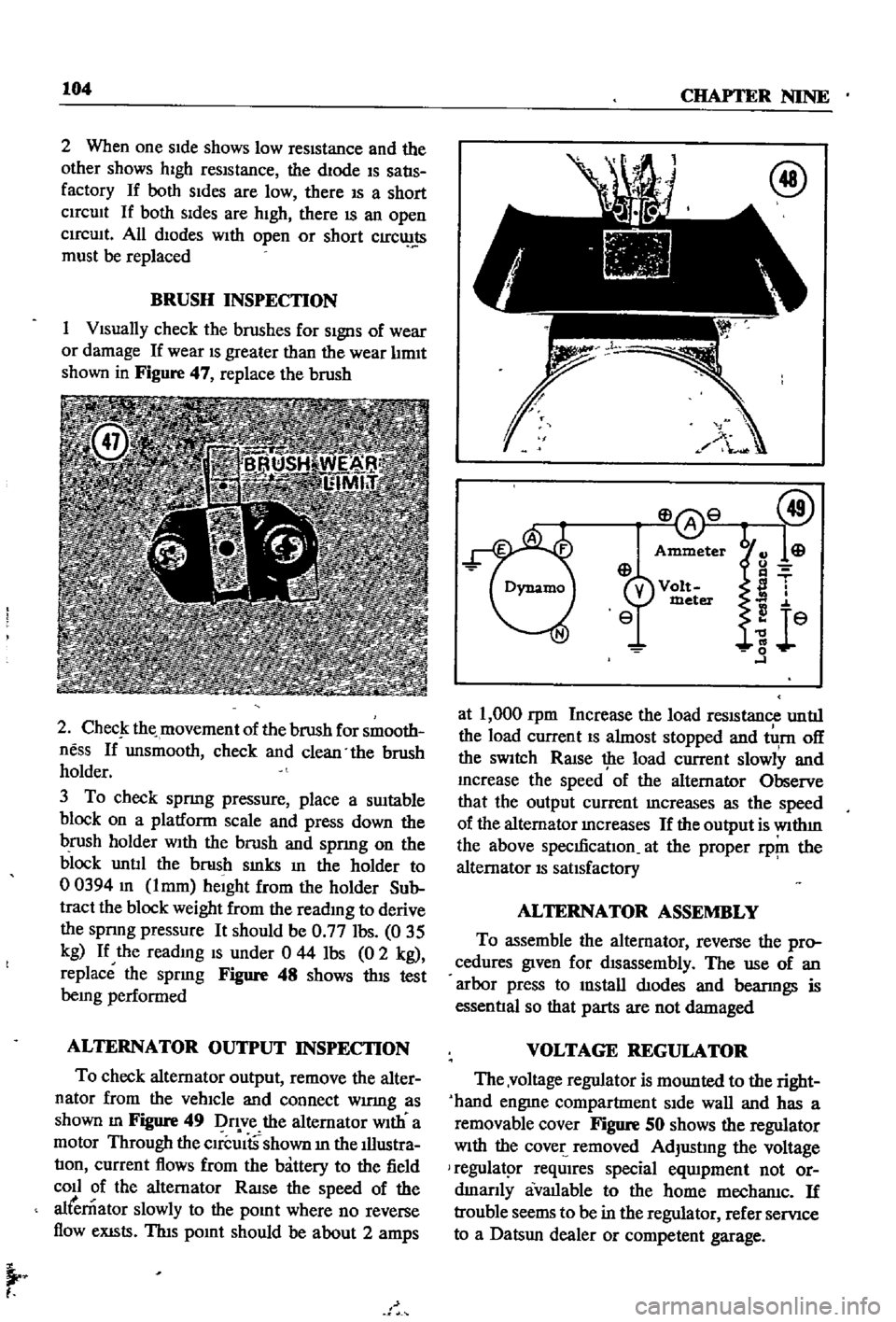
BRUSH
INSPECTION
1
VIsually
check
the
brushes
for
SIgnS
of
wear
or
damage
If
wear
IS
greater
than
the
wear
lIrmt
shown
in
Figure
47
replace
the
brush
2
ChecJ
the
movement
of
the
brush
for
smooth
ness
If
unsmooth
check
and
clean
the
brush
holder
3
To
check
spnng
pressure
place
a
SUItable
block
on
a
platform
scale
and
press
down
the
brush
holder
WIth
the
brush
and
spnng
on
the
block
untIl
the
brush
smks
In
the
holder
to
00394
m
lmm
heIght
from
the
holder
Sub
tract
the
block
weight
from
the
reading
to
derive
the
spnng
pressure
It
should
be
0
77
Ibs
035
kg
If
the
readmg
IS
under
0
44
Ibs
0
2
kg
replace
the
spring
Figure
48
shows
thIS
test
being
performed
ALTERNATOR
OUTPUT
INSPECTION
To
check
alternator
output
remove
the
alter
nator
from
the
vehIcle
and
connect
wumg
as
shown
m
Figure
49
Dq
ve
the
alternator
WIth
a
motor
Through
the
CIrcUItS
shown
m
the
Illustra
tIon
current
flows
from
the
battery
to
the
field
coll
of
the
alternator
RaISe
the
speed
of
the
alternator
slowly
to
the
pOInt
where
no
reverse
flow
eXISts
ThIs
pOInt
should
be
about
2
amps
I
at
1
000
rpm
Increase
the
load
reSIStance
untIl
the
load
current
IS
almost
stopped
and
tlI
rn
off
the
SWItch
RaIse
the
load
current
slowly
and
mcrease
the
speed
of
the
alternator
Observe
that
the
output
current
mcreases
as
the
speed
of
the
alternator
mcreases
If
the
output
is
wlthm
the
above
specmcatIon
at
the
proper
rp
ll
the
alternator
IS
satIsfactory
ALTERNATOR
ASSEMBLY
To
assemble
the
alternator
reverse
the
pro
cedures
given
for
dIsassembly
The
use
of
an
arbor
press
to
mstall
dIodes
and
bearmgs
is
essentIal
so
that
parts
are
not
damaged
VOLTAGE
REGULATOR
The
voltage
regulator
is
mounted
to
the
right
hand
engme
compartment
SIde
wall
and
has
a
removable
cover
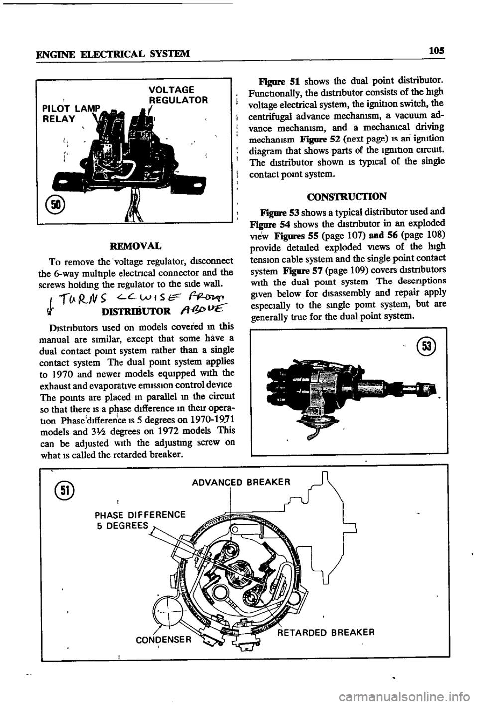
Figure
SO
shows
the
regulator
With
the
cover
removed
AdjustIng
the
voltage
regulatpr
reqUIres
special
eqUIpment
not
or
dmanly
avallable
to
the
home
mechanlc
If
trouble
seems
to
be
in
the
regulator
refer
servIce
to
a
Datsun
dealer
or
competent
garage
Page 110 of 252
ENGINE
ELECTRICAL
SYSTEM
105
VOLTAGE
REGULATOR
REMOVAL
To
remove
the
voltage
regulator
dISconnect
the
6
way
multIple
electrIcal
COlInector
and
the
screws
holdmg
the
regulator
to
the
SIde
wall
lJ
R
ftl5
C
Wt
Str
Ii
DISTRIBUTOR
W
I
vE
Dlstnbutors
used
on
models
covered
m
this
manual
are
SImilar
except
that
some
have
a
dual
contact
pomt
system
rather
than
a
single
contact
system
The
dual
pomt
system
applies
to
1970
and
newer
models
eqUIpped
With
the
exhaust
and
evaporatIve
ermsslOn
control
deVIce
The
pomts
are
placed
m
parallel
In
the
circuIt
so
that
there
IS
a
pqase
dIfference
In
their
opera
tIon
Phase
dlfference
IS
5
degrees
on
1970
19
71
models
and
31h
degrees
on
1972
models
This
can
be
adjusted
With
the
adjustIng
screw
on
what
IS
called
the
retarded
breaker
Figure
51
shows
the
dual
point
distributor
FunctIonally
the
dIStnbutor
consists
of
the
hIgh
voltage
electrical
system
the
ignitIon
switch
the
centrifugal
advance
mechanISm
a
vacuum
ad
vance
mechanIsm
and
a
mechanIcal
driving
mechanISm
Figure
52
next
page
IS
an
ignItion
diagram
that
shows
parts
of
the
IgnItIon
CIrCUIt
The
dIstributor
shown
IS
typIcal
of
the
single
contact
pomt
system
CONSTRUCTION
Figure
53
shows
a
typical
distributor
used
and
Figure
54
shows
the
dIStnbutor
in
an
exploded
VIeW
Figures
55
page
107
and
56
page
108
provide
detaIled
exploded
VIews
of
the
lugh
tenSIon
cable
system
and
the
single
point
contact
system
Figure
57
page
109
covers
dIStrIbutors
With
the
dual
pOInt
system
The
descnptions
given
below
for
dIsassembly
and
repair
apply
espeCIally
to
the
smgle
pOInt
system
but
are
generally
true
for
the
dual
point
system
@
@
ADVANCED
BREAKER
PHASE
DIFFERENCE
5
DEGREES