DATSUN 510 1968 Service Owners Manual
Manufacturer: DATSUN, Model Year: 1968, Model line: 510, Model: DATSUN 510 1968Pages: 252, PDF Size: 12.2 MB
Page 91 of 252
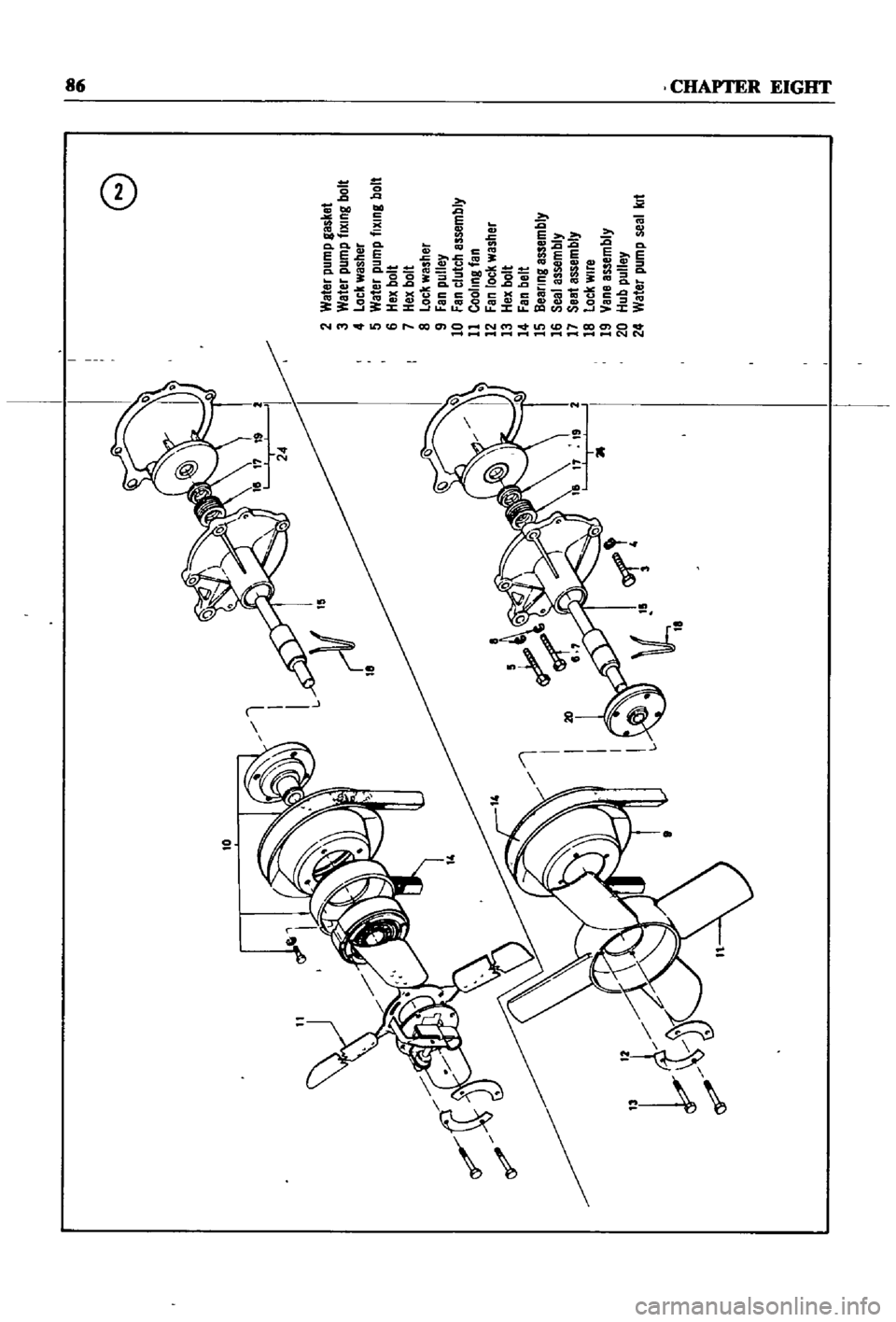
10
f
e
2
Weter
pump
gasket
3
Water
pump
tlXlng
bolt
4
Lock
washer
5
Water
pump
tlXlng
bolt
6
Hex
bolt
7
Hex
bolt
8
Lock
washer
9
Fan
pulley
10
Fan
clutch
assembly
11
Cooling
tan
12
Fan
lock
washer
13
Hex
bolt
14
Fan
belt
15
Dealing
assembly
16
Seal
assembly
17
Seatassembly
18
Lock
wire
19
Vane
assembly
20
Hub
pulley
24
Water
pump
seal
kit
Illl
t
l
Page 92 of 252
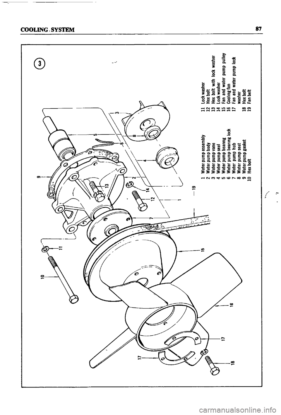
10
9
8
n
o
o
19
1
Water
pump
assembly
11
lock
washer
2
Water
pump
body
12
Hex
bolt
3
Water
pump
ane
13
Hex
bolt
With
lock
washer
4
Water
pump
seal
14
loc
l
washer
17
6
5
Water
pump
beanng
15
Fan
and
water
pump
pulley
6
Water
pump
bee
ring
lock
16
Cooling
tan
7
Water
pump
hub
17
Fan
and
water
pump
lock
8
Water
pump
seat
washer
9
Water
pump
gasket
18
Hex
bolt
10
Hex
bolt
19
Fen
belt
I
I
Page 93 of 252
CllAyrElt
EiGll
f
CD
6
1
al
co
t
Sl
1
0
gi
s
co
Oc
3
o
P
c
0
0
tl6
e
cOQ
i
i
fNt
l
tDr
Page 94 of 252
COOLING
SYSTEM
89
FAN
CLUTCH
Fan
Clutch
Operation
and
Inspection
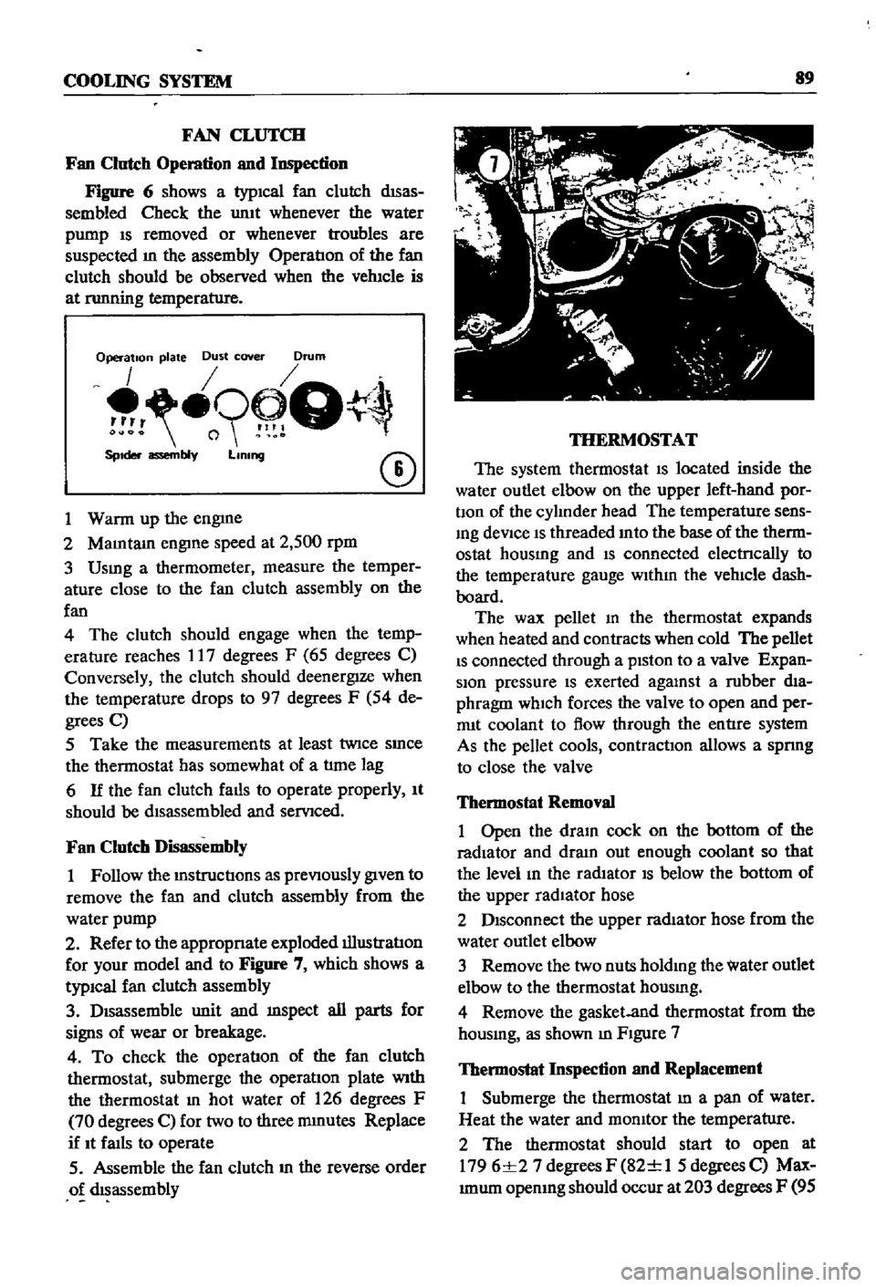
Figure
6
shows
a
typICal
fan
clutch
dISas
sembled
Check
the
umt
whenever
the
water
pump
IS
removed
or
whenever
troubles
are
suspected
m
the
assembly
OperatIon
of
the
fan
clutch
should
be
observed
when
the
vehIcle
is
at
nmning
temperature
Operation
plate
Dust
cover
Drum
o9
Q
SpIder
assembly
LIning
CD
1
Warm
up
the
engme
2
MaIntam
engIne
speed
at
2
500
rpm
3
Usmg
a
thermometer
measure
the
temper
ature
close
to
the
fan
clutch
assembly
on
the
fan
4
The
clutch
should
engage
when
the
temp
erature
reaches
17
degrees
F
65
degrees
C
Conversely
the
clutch
should
deenergIze
when
the
temperature
drops
to
97
degrees
F
54
de
grees
C
5
Take
the
measurements
at
least
twice
SInce
the
thermostat
has
somewhat
of
a
tlme
lag
6
If
the
fan
clutch
falls
to
operate
properly
It
should
be
dIsassembled
and
servIced
Fan
Clutch
Disassembly
1
Follow
the
mstructIons
as
prevIOusly
gIven
to
remove
the
fan
and
clutch
assembly
from
the
water
pump
2
Refer
to
the
appropnate
exploded
illustratIon
for
your
model
and
to
Figure
7
which
shows
a
typiCal
fan
clutch
assembly
3
DIsassemble
unit
and
mspect
all
parts
for
signs
of
wear
or
breakage
4
To
check
the
operatIon
of
the
fan
clutch
thermostat
submerge
the
operatIon
plate
With
the
thermostat
In
hot
water
of
126
degrees
F
70
degrees
C
for
two
to
three
mmutes
Replace
if
It
faIls
to
operate
5
Assemble
the
fan
clutch
m
the
reverse
order
o
dIsassembly
THERMOSTAT
The
system
thermostat
IS
located
inside
the
water
outlet
elbow
on
the
upper
left
hand
por
bon
of
the
cylInder
head
The
temperature
sens
Ing
deVice
IS
threaded
Into
the
base
of
the
therm
ostat
housmg
and
IS
connected
electrlcally
to
the
temperature
gauge
WIthIn
the
vehIcle
dash
board
The
wax
pellet
m
the
thermostat
expands
when
heated
and
contracts
when
cold
The
pellet
IS
connected
through
a
pIston
to
a
valve
Expan
sion
pressure
IS
exerted
agalUst
a
rubber
dIa
phragm
which
forces
the
valve
to
open
and
per
rrut
coolant
to
flow
through
the
entIre
system
As
the
pellet
cools
contractIOn
allows
a
spnng
to
close
the
valve
Thermostat
Removal
1
Open
the
draIn
cock
on
the
bottom
of
the
radiator
and
dram
out
enough
coolant
so
that
the
level
In
the
radIator
IS
below
the
bottom
of
the
upper
radIator
hose
2
DIsconnect
the
upper
radIator
hose
from
the
water
outlet
elbow
3
Remove
the
two
nuts
holdIng
the
water
outlet
elbow
to
the
thermostat
housmg
4
Remove
the
gasket
and
thermostat
from
the
housmg
as
shown
m
FIgure
7
Thermostat
Inspection
and
Replacement
Submerge
the
thermostat
In
a
pan
of
water
Heat
the
water
and
momtor
the
temperature
2
The
thermostat
should
start
to
open
at
1796
1
27
degrees
F
82
1
1
5
degrees
C
Max
Imum
opemng
should
occur
at
203
degrees
F
95
Page 95 of 252
90
CHAPTER
EIGHT
degrees
C
The
maXImum
WIdth
of
the
thermo
stat
openIng
should
be
0315
In
8mm
3
If
the
thermostat
IS
defectIve
or
If
you
have
an
doubts
about
It
mstall
a
new
one
4
When
Installmg
the
thermostat
m
the
hous
Ing
be
certaIn
to
place
the
spnng
end
down
Coat
both
SIdes
of
the
gasket
WIth
sealer
to
pre
vent
leaks
and
tIghten
the
mountlng
nuts
securely
RADIATOR
The
radIator
IS
of
conventional
desIgn
A
draIn
cock
IS
proVIded
at
the
bottom
back
to
perrmt
drainIng
The
system
IS
pressurized
and
the
rehef
valve
incorporated
In
the
filler
cap
mamtains
the
pressure
at
approximately
12
8
Ib
in
0
9
kg
cm
Coolant
capacity
is
1
691
gallons
6
4
lIters
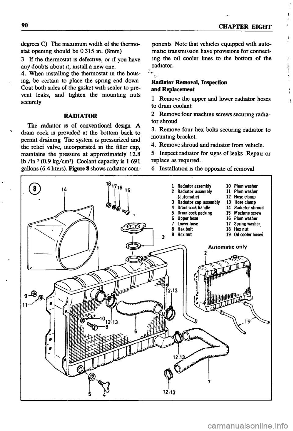
Figure
8
shows
radIator
com
ponents
Note
that
vehicles
equIpped
WIth
auto
matIc
transmISSIon
have
provlSlons
for
connect
Ing
the
011
cooler
lInes
to
the
bottom
of
the
radiator
Radiator
Removal
Inspection
and
Replacement
1
Remove
the
upper
and
lower
radIator
hoses
to
draIn
coolant
2
Remove
four
machme
screws
securmg
radIa
tor
shroud
3
Remove
four
hex
bolts
secunng
rad1ator
to
mountlng
bracket
4
Remove
shroud
and
radIator
from
vehIcle
5
Inspect
radIator
for
SignS
of
leaks
RepaIr
or
replace
as
required
6
InstallatIon
IS
the
OppOSIte
of
removal
CD
14
1
Radiator
assembly
10
Plain
washer
2
Radiator
assembly
11
Plain
washer
automal1c
12
Hose
clamp
3
RadIator
cap
assembly
13
Hose
clamp
4
Drain
cock
handle
14
Radiator
shroud
5
Drain
cock
packing
15
Machine
screw
6
Upper
hose
16
Plain
washer
7
Lower
hose
17
Spring
washer
8
Hex
bolt
18
Hex
nut
9
Hex
nut
19
011
cooler
hoses
Automatic
only
2
i
7
1213
Page 96 of 252
CHAPTER
NINE
ENGINE
ELECTRICAL
SYSTEM
The
electrIcal
system
has
undergone
slIght
yearly
changes
the
most
SignIficant
being
ill
the
distrIbutor
Some
models
have
a
smgle
contact
pomt
whIle
others
have
a
dual
pomt
system
De
talls
are
covered
m
the
dIstrIbutor
sectlon
The
electrIcal
system
IS
a
12
volt
negatIve
type
OPERATION
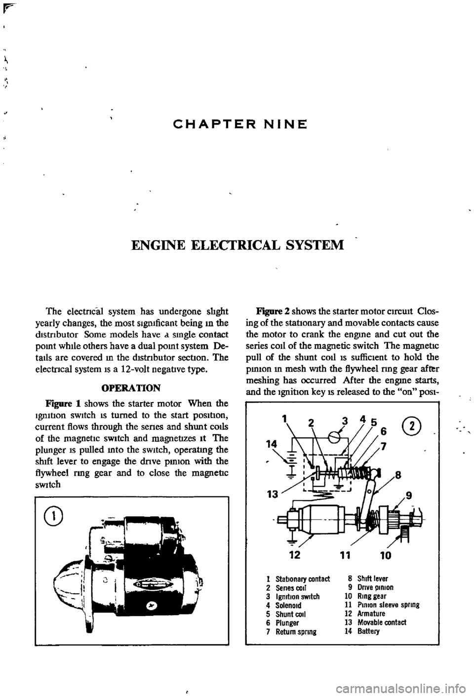
Figure
1
shows
the
starter
motor
When
the
Ignltlon
sWItch
IS
turned
to
the
start
pOSItIon
current
flows
through
the
senes
and
shunt
colis
of
the
magnetIc
SWitch
and
magnetizes
It
The
plunger
IS
pulled
mto
the
sWItch
operatlng
the
shIft
lever
to
engage
the
dnve
pmlon
with
the
flywheel
rmg
gear
and
to
close
the
magnetIc
SWitch
CD
Figure
2
shows
the
starter
motor
CIrcUIt
Clos
ing
of
the
statlonary
and
movable
contacts
cause
the
motor
to
crank
the
engme
and
cut
out
the
series
coIl
of
the
magnetic
switch
The
magnetic
pull
of
the
shunt
coll
IS
suffiCIent
to
hold
the
pmIOn
m
mesh
With
the
flywheel
nng
gear
after
meshing
has
occurred
After
the
engme
starts
and
the
Ignition
key
IS
released
to
the
on
POSI
1
CD
12
11
10
1
Stationary
contact
8
ShIlt
le
er
2
Sene
coli
9
Orne
pinion
3
IgmtlOn
SWitch
10
Ring
gear
4
Solenoid
11
Plmon
slee
e
spllng
5
Shunt
COil
12
Armature
6
Plunger
13
Movable
contact
7
Return
spllng
14
Battery
Page 97 of 252

91
CHAPTER
NINE
bon
the
serIes
coll
demagnetizes
agatnst
the
shunt
cOIl
The
return
spnng
causes
the
plunger
to
return
to
the
origmal
posItIon
stoppmg
the
starter
The
overrunnmg
clutch
provIdes
for
positIve
meshmg
and
unmeshmg
of
the
pmlOn
gear
and
flywheerrmg
gear
and
perinitStlie
pmlon
to
overrun
the
armature
after
the
engme
has
started
CONSTRUCIlON
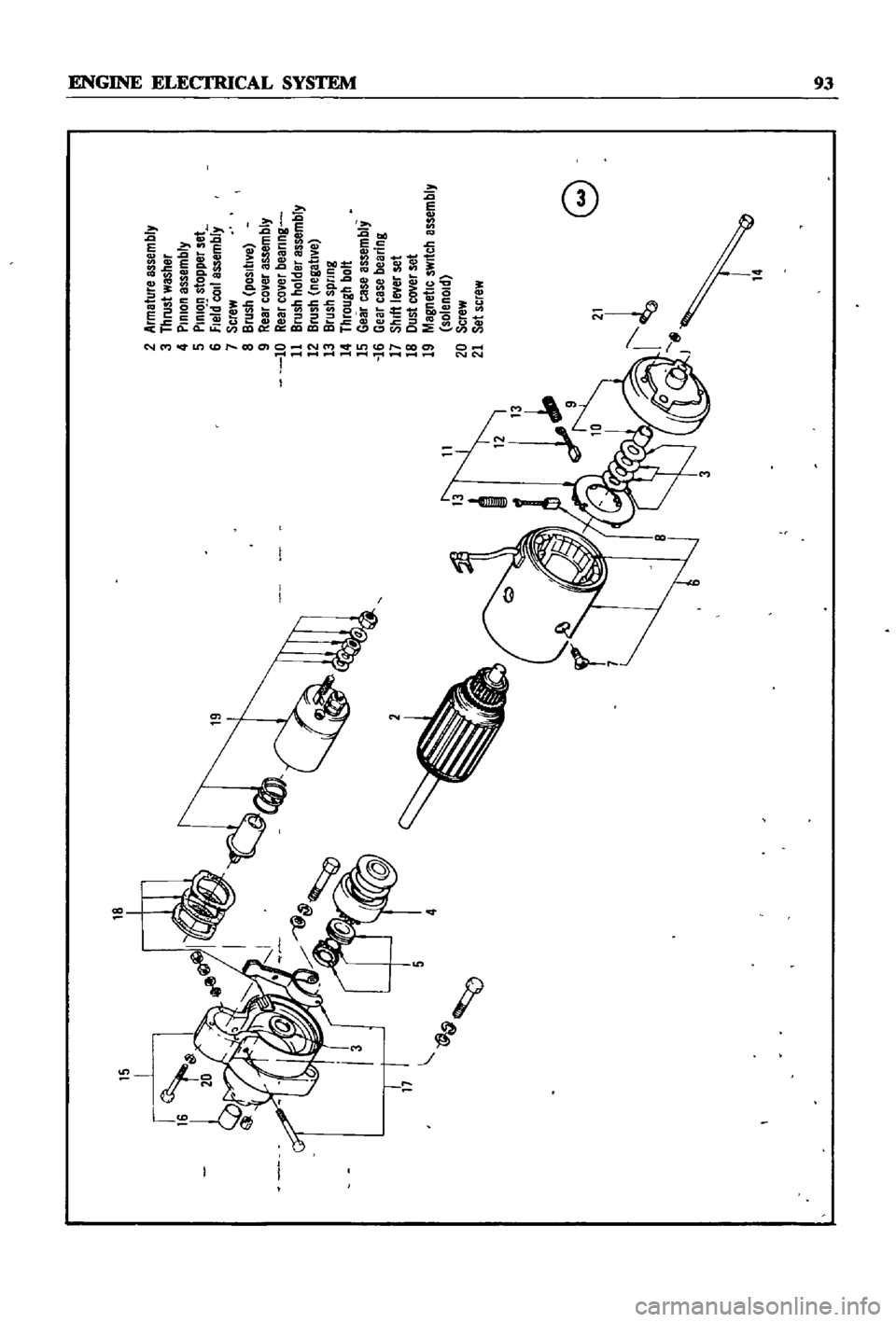
A
typical
Datsun
starter
motor
is
shown
m
Figure
3
The
example
is
for
1971
models
but
about
the
only
dIfferences
existing
between
It
and
other
models
are
the
number
of
elements
used
in
the
dust
cover
and
the
number
of
thrust
washers
Removal
1
DIsconnect
the
battery
ground
cable
2
Disconnect
the
black
yellow
wire
from
the
magnetIc
sWitch
tennmal
on
the
solenoid
3
Disconnect
the
black
battery
cable
and
red
wire
from
the
battery
tennmal
on
the
solenOId
4
Remove
two
bolts
holdmg
the
startmg
motor
to
flywheel
hOUSIng
The
battery
ground
cable
is
attached
to
the
flywheel
hOUSIng
bottom
bolt
5
Pull
starter
motor
toward
front
of
engme
and
remove
Disassembly
1
Remove
the
nut
holdIng
the
electrIc
WIre
to
the
magnetIc
sWItch
M
tennmal
DIsconnect
the
WIre
2
Remove
three
screws
securmg
magnetic
switch
assembly
to
yoke
Remove
magnetic
sWItch
assembly
and
dust
cover
s
Figure
4
3
Remove
two
through
bolts
and
brush
cover
assembly
as
shown
m
Figure
5
4
Remove
the
yoke
assembly
by
tappmg
lIghtly
as
In
Figure
6
5
Remove
bolt
nut
and
washers
at
base
of
yoke
to
free
shut
lever
WIthdraw
the
armatlIre
and
shut
lever
as
shown
m
Figure
7
6
Remove
the
pInIOn
stop
nng
located
at
the
end
of
the
armature
shaft
To
remove
the
stop
nng
push
the
stop
nng
to
the
clutch
SIde
remove
the
snap
nng
and
Withdraw
the
stop
nng
and
CD
c
0
I
CD
Ml
ml
CD
a
I
II
0
l
g
I
o
Page 98 of 252
5
2
Armeture
assembly
3
thrust
washer
4
PinIon
assembly
5
PInion
stopper
set
6
fle
rCOJ1
assembly
7
Screw
8
Brush
positIVe
9
Reer
co
er
assembly
10
Rear
co
er
beerlng
11
Brush
holder
essembly
12
Brush
negatl
e
13
Brush
spnng
14
through
bolt
15
Gear
case
essembly
16
Gear
case
bearing
17
Shift
Iwer
set
18
Oust
cover
set
19
Magnetic
sWitch
assembly
solenoid
20
Screw
21
Set
screw
4
@
e
rl
14
i
i
j
Page 99 of 252
94
CHAPTER
NINE
clutch
WIthdraw
the
overrunnmg
clutch
assem
bly
from
the
armature
shaft
as
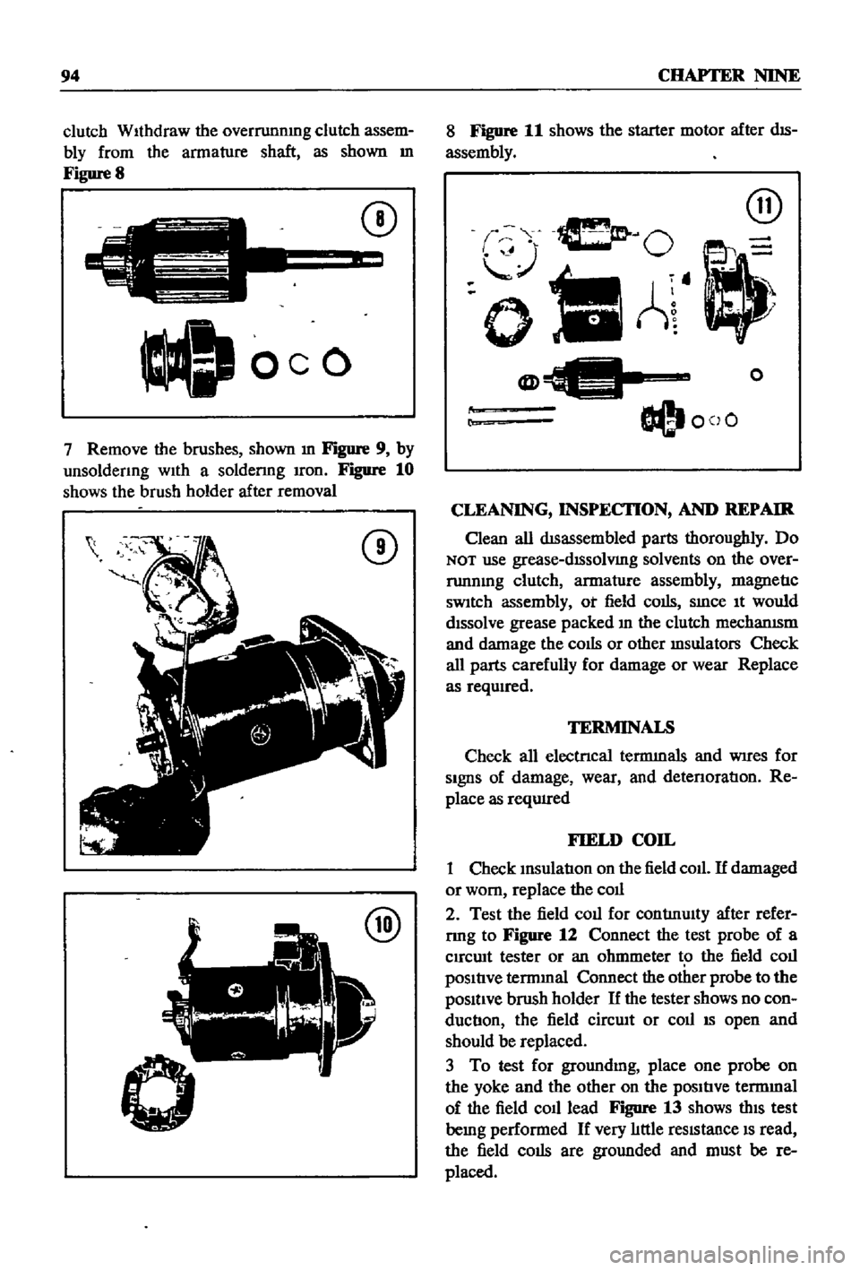
shown
m
Figure
8
C
J
oeo
CD
7
Remove
the
brushes
shown
m
Figure
9
by
unsoldenng
wIth
a
soldenng
Iron
Figure
10
shows
the
brush
holder
after
removal
CD
@
8
Figure
11
shows
the
starter
motor
after
dIS
assembly
@
O
oIlA
@
O@I
coO
o
r
CLEANING
INSPECI10N
AND
REPAIR
Clean
all
dISassembled
parts
thoroughly
Do
NOT
use
grease
dISsolVIng
solvents
on
the
over
runnmg
clutch
armature
assembly
magnetIc
sWItch
assembly
ot
field
colis
SInce
It
would
dIssolve
grease
packed
In
the
clutch
mechanISm
and
damage
the
cOIls
or
other
msulators
Check
all
parts
carefully
for
damage
or
wear
Replace
as
reqwred
TERMINALS
Check
all
electrIcal
termInals
and
WIres
for
SIgnS
of
damage
wear
and
detenoratIon
Re
place
as
reqUIred
FIELD
COIL
1
Check
InsulatIon
on
the
field
coll
If
damaged
or
worn
replace
the
coll
2
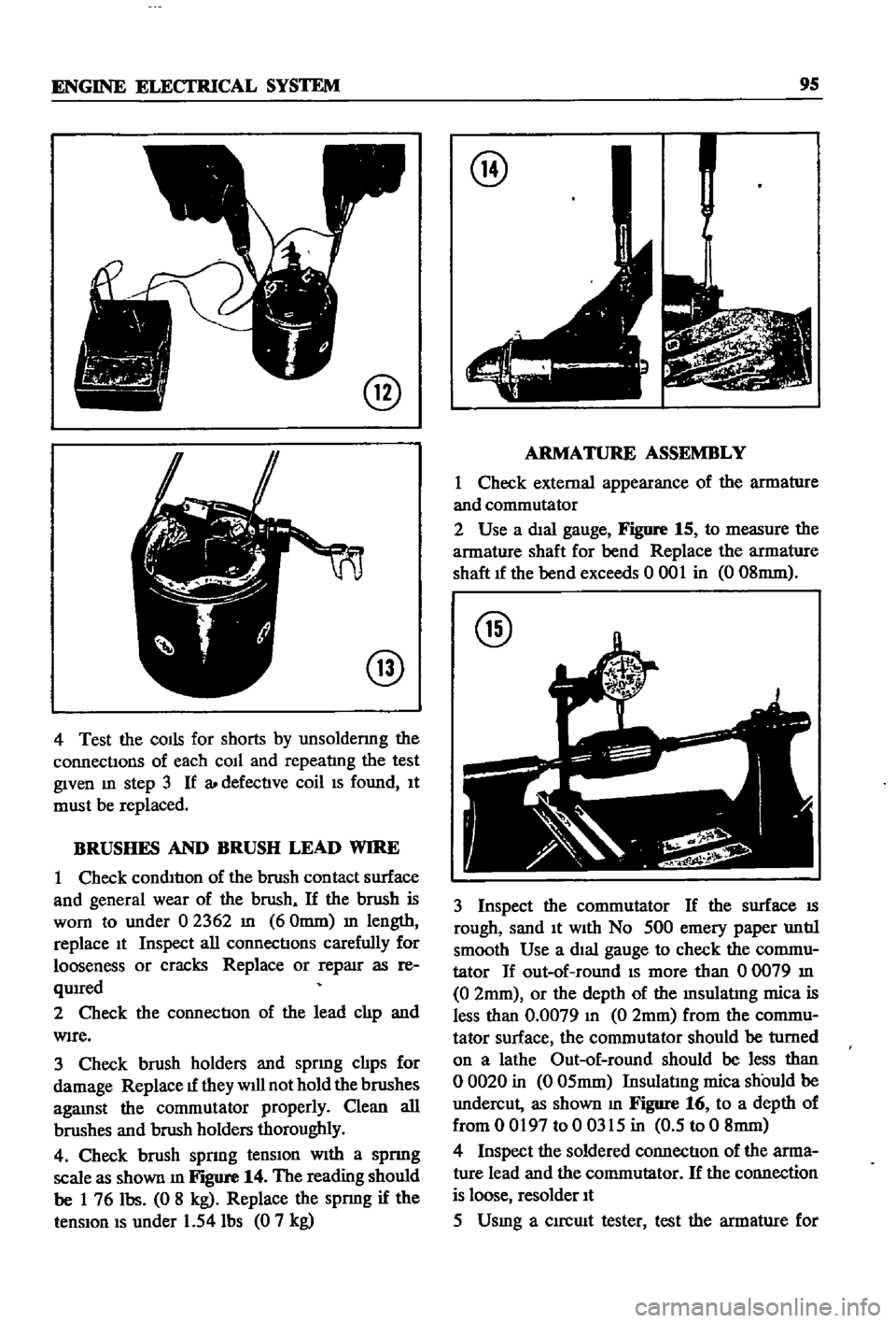
Test
the
field
coll
for
contlnulty
after
refer
rmg
to
Figure
12
Connect
the
test
probe
of
a
Clrcwt
tester
or
an
ohmmeter
t
the
field
coll
pOSItIve
termInal
Connect
the
other
probe
to
the
pOSItIve
brush
holder
If
the
tester
shows
no
con
ductIon
the
field
cirCUIt
or
coll
IS
open
and
should
be
replaced
3
To
test
for
groundmg
place
one
probe
on
the
yoke
and
the
other
on
the
pOSItIve
termmal
of
the
field
co1l1ead
Figure
13
shows
thIS
test
bemg
performed
If
very
lIttle
reSIstance
IS
read
the
field
colis
are
grounded
and
must
be
re
placed
Page 100 of 252
ENGINE
ELECI
RlCAL
SYSTEM
9S
@
@
4
Test
the
COIls
for
shorts
by
unsoldermg
the
connectIons
of
each
coIl
and
repeatlng
the
test
given
m
step
3
If
a
defectIve
coil
IS
found
It
must
be
replaced
BRUSHES
AND
BRUSH
LEAD
WIRE
1
Check
condItIon
of
the
brush
contact
surface
and
general
wear
of
the
brush
If
the
brush
is
worn
to
under
02362
In
60mm
m
length
replace
It
Inspect
all
connectIons
carefully
for
looseness
or
cracks
Replace
or
reparr
as
re
qUIred
2
Check
the
connectIon
of
the
lead
clIp
and
WIre
3
Check
brush
holders
and
sprmg
clIps
for
damage
Replace
1f
they
will
not
hold
the
brushes
agaInst
the
commutator
properly
Clean
all
brushes
aIld
brush
holders
thoroughly
4
Check
brush
sprmg
tenSIon
WIth
a
spnng
scale
as
shown
m
Figure
14
The
reading
should
be
1
76
Ibs
0
8
kg
Replace
the
spnng
if
the
tenSIon
IS
under
1
54
Ibs
0
7
kg
@
ARMATURE
ASSEMBLY
1
Check
external
appearance
of
the
armature
and
commutator
2
Use
a
dIal
gauge
Figure
15
to
measure
the
armature
shaft
for
bend
Replace
the
armature
shaft
1f
the
bend
exceeds
0
001
in
0
08mm
@
3
Inspect
the
commutator
If
the
surface
IS
rough
sand
It
With
No
500
emery
paper
untIl
smooth
Use
a
dIal
gauge
to
check
the
commu
tator
If
out
of
round
IS
more
than
00079
In
0
2mm
or
the
depth
of
the
Insulatlng
mica
is
less
than
0
0079
In
0
2mm
from
the
commu
tator
surface
the
commutator
should
be
turned
on
a
lathe
Out
of
round
should
be
less
than
o
0020
in
0
05mm
Insulatmg
mica
should
be
undercut
as
shown
m
Figure
16
to
a
depth
of
from
0
0197
to
0
0315
in
0
5
to
0
8mm
4
Inspect
the
soldered
connectIon
of
the
arma
ture
lead
and
the
commutator
If
the
connection
is
loose
resolder
It
5
Usmg
a
clrcmt
tester
test
the
armature
for