engine DATSUN B110 1973 Service Repair Manual
[x] Cancel search | Manufacturer: DATSUN, Model Year: 1973, Model line: B110, Model: DATSUN B110 1973Pages: 513, PDF Size: 28.74 MB
Page 468 of 513
ENGINE
REMOVAL
INSTAllATION
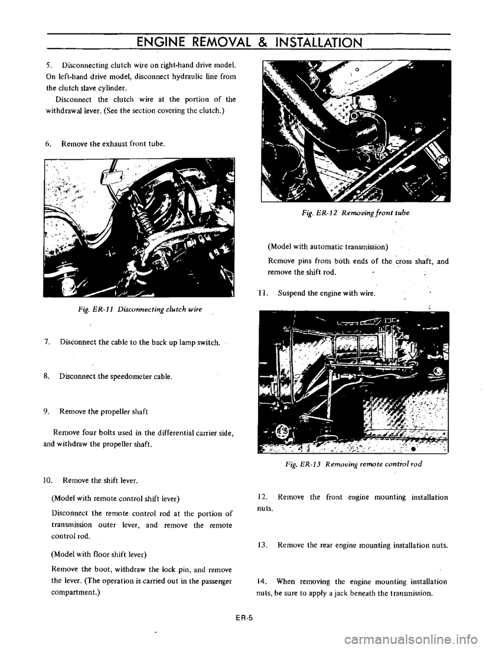
5
Disconnecting
clutch
wire
on
right
hand
drive
model
On
left
hand
drive
model
disconnect
hydraulic
line
from
the
clutch
slave
cylinder
Disconnect
the
clutch
wire
at
the
portion
of
the
withdrawal
lever
See
the
section
covering
the
clutch
6
Remove
the
exhaust
front
tube
ij
f
I
Fig
ER
11
Disconnecting
dutch
wire
7
Disconnect
the
cable
to
the
back
up
lamp
switch
8
Disconnect
the
speedometer
cable
9
Remove
the
propeller
shaft
Remove
four
bolts
used
in
the
differential
carrier
side
and
withdraw
the
propeller
shaft
10
Remove
the
shift
lever
Model
with
remote
control
shift
lever
Disconnect
the
remote
control
rod
at
the
portion
of
transmission
outer
lever
and
remove
the
remote
control
rod
Model
with
floor
shift
lever
Remove
the
boot
withdraw
the
lock
pin
and
remove
the
lever
The
operation
is
carried
out
in
the
passenger
compartment
Fig
ER
12
Removing
fTont
tube
Model
with
automatic
transmission
Remove
pins
from
both
ends
of
the
cross
shaft
and
remove
the
shift
rod
II
Suspend
the
engine
with
wire
Fig
ER
13
Removing
remote
control
rod
12
Remove
the
front
engine
mounting
installation
nuts
13
Remove
the
rear
engine
mounting
installation
nuts
14
When
removing
the
engine
mounting
installation
nuts
be
sure
to
apply
a
jack
beneath
the
transmission
ER
5
Page 469 of 513
15
Lift
up
the
engine
toward
the
front
INSTALLATION
Install
the
engine
in
reverse
sequence
of
removal
CHASSIS
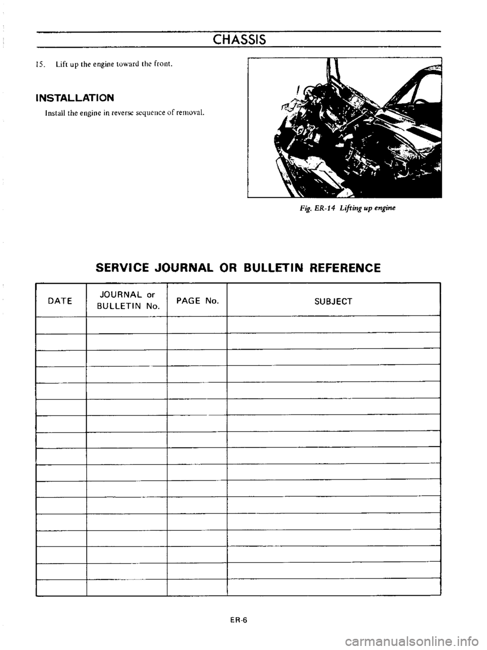
Fig
ER
14
Lifting
up
engine
SERVICE
JOURNAL
OR
BULLETIN
REFERENCE
DATE
JOURNAL
or
BULLETIN
No
PAGE
No
ER
6
SUBJECT
Page 472 of 513
CHASSIS
REMOVAL
The
clutch
assembly
is
dismounted
primarily
in
the
same
manner
as
the
engine
assembly
Thus
when
dis
mounting
the
clutch
assembly
refer
to
the
Section
TM
Transmission
Removal
and
other
relative
sections
W
II
11
I
Clutch
assembly
I
2
I
Clutch
disc
assembly
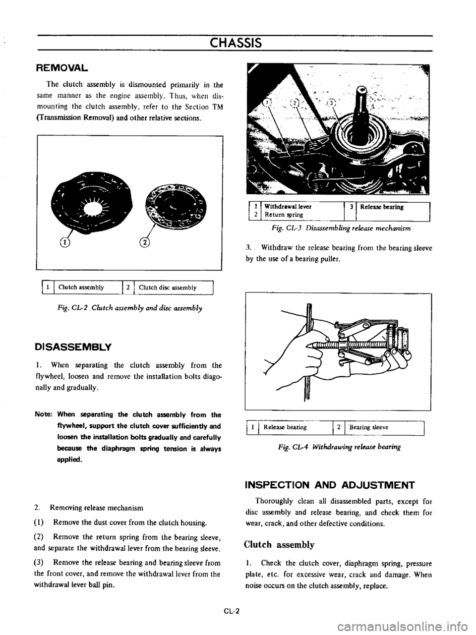
Fig
CIr2
Clutch
assembly
and
disc
assembly
DISASSEMBLY
When
separating
the
clutch
assembly
from
the
flywheel
loosen
and
remove
the
installation
bolts
diago
nally
and
gradually
Note
When
separating
the
clutch
assembly
from
the
flywheel
support
the
clutch
cover
sufficiently
and
loosen
the
installation
bolts
gradually
and
carefully
because
the
diaphragm
spring
tension
is
always
applied
2
Removing
release
mechanism
I
Remove
the
dust
cover
from
the
clutch
housing
2
Remove
the
return
spring
from
the
bearing
sleeve
and
separate
the
withdrawal
lever
from
the
bearing
sleeve
3
Remove
the
release
bearing
and
bearing
sleeve
from
the
front
cover
and
remove
the
withdrawal
lever
from
the
withdrawal
lever
ball
pin
1
I
Withdrawal
lever
3
Release
bearing
2
Return
spring
Fig
CL
3
Disassembling
release
mechanism
3
Withdraw
the
release
bearing
from
the
bearing
sleeve
by
the
use
of
a
bearing
puller
I
t
I
Release
bearing
I
2
I
Bearing
sleeve
Fig
CIr4
Withdrawing
rekas
b04ring
INSPECTION
AND
ADJUSTMENT
Thoroughly
clean
all
disassembled
parts
except
for
disc
assembly
and
release
bearing
and
check
them
for
wear
crack
and
other
defective
conditions
Clutch
assembly
I
Check
the
clutch
cover
diaphragm
spring
pressure
plate
etc
for
excessive
wear
crack
and
damage
When
noise
occurs
on
the
clutch
assembly
replace
CL
2
Page 483 of 513
CLUTCH
Operating
cylinder
clutch
Operating
cylinder
diameter
T
Ilhtening
torque
19
05
mm
0
750
in
Clutch
assembly
securing
bolt
1
5
to
2
2
kg
m
10
8
to
15
9
ft
Ib
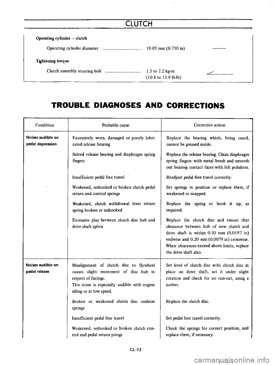
TROUBLE
DIAGNOSES
AND
CORRECTIONS
Condition
Noises
audible
on
pedal
depression
Noises
audible
on
pedal
release
Probable
cause
Excessively
worn
damaged
or
poorly
lubri
cated
release
bearing
Seized
release
bearing
and
diaphragm
spring
fingers
Insufficient
pedal
free
travel
Weakened
unhooked
or
broken
clutch
pedal
return
and
control
springs
Weakened
clutch
withdrawal
lever
return
spring
broken
or
unhooked
Excessive
play
between
clutch
disc
hub
and
drive
shaft
spline
Misalignment
of
clutch
disc
to
flywheel
causes
slight
movement
of
disc
hub
in
respect
of
facings
This
noise
is
especially
audible
with
engine
idling
or
at
low
speed
Broken
or
weakened
clutch
disc
cushion
springs
Insufficient
pedal
free
travel
Weakened
unhooked
or
broken
clutch
con
trol
and
pedal
return
prings
CL
13
Corrective
action
Replace
the
bearing
which
being
cased
cannot
be
greased
inside
Replace
the
release
bearing
Clean
diaphragm
spring
fingers
with
metal
brush
and
smooth
out
bearing
contact
faces
with
felt
polishers
Readjust
pedal
free
travel
correctly
Set
springs
in
position
or
replace
them
if
weakened
or
snapped
Replace
the
spring
or
hook
it
up
as
required
Replace
the
clutch
disc
and
ensure
that
clearance
between
hub
of
new
clutch
and
drive
shaft
is
within
0
50
mm
0
0197
in
endwise
and
0
20
mm
0
0079
in
crosswise
When
clearances
exceed
above
limits
replace
the
drive
shaft
also
Set
level
of
clutch
disc
with
clutch
disc
in
place
on
drive
shaft
set
it
under
slight
rotation
and
check
for
no
run
out
using
a
scriber
Replace
the
clutch
disc
Set
pedal
free
travel
correctly
Check
the
springs
for
correct
position
and
replace
them
if
necessary
Page 488 of 513
TRANSMISSION
TRANSMISSION
CONTENTS
DESCRIPTION
Specifications
REMOVAL
DISASSEMBLY
INSPECTION
Transmission
case
and
rear
extension
Bearing
Gear
and
shaft
TM
l
TM
l
TM
2
TM
4
TM
7
TM
7
TM
8
TM
8
DESCRIPTION
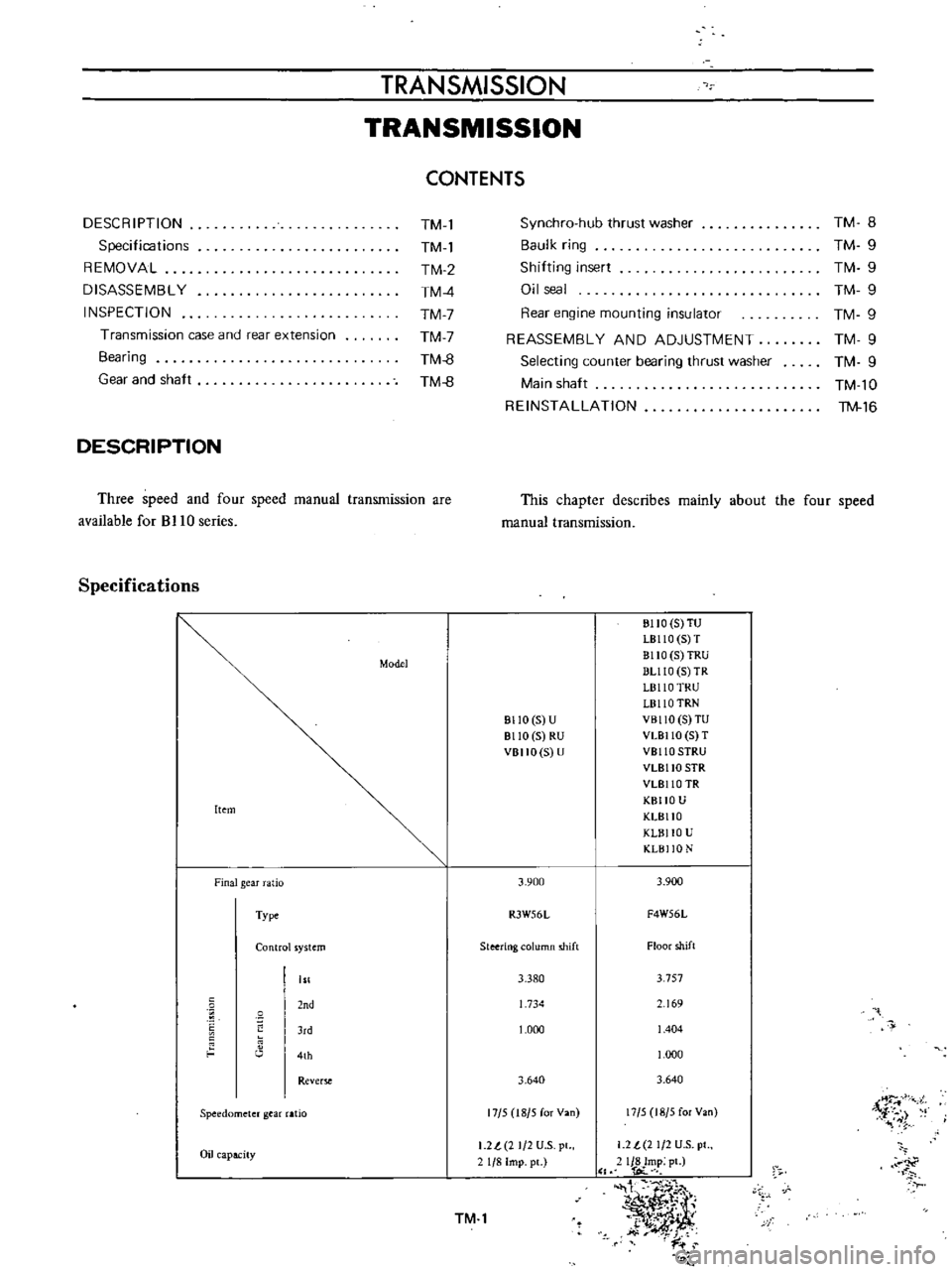
Three
speed
and
four
speed
manual
transmission
are
available
for
BJ
10
series
Specifications
Model
Item
Finalgear
atio
Type
Control
ystem
nd
J
d
4th
Rever
Speedometer
gear
aHo
Oil
apacity
TM
8
TM
9
TM
9
TM
9
TM
9
TM
9
TM
9
TM
l0
TM
16
Synchro
hub
thrust
washer
Baulk
ring
Shilting
insert
Oil
seal
Rear
engine
mounting
insulator
REASSEMBLY
AND
ADJUSTMENT
Selecting
counter
bearing
thrust
washer
Main
shaft
REINSTALLATION
This
chapter
describes
mainly
about
the
four
speed
manual
transmission
811O
5
U
8110
5
RU
VBIIO
S
U
3
900
R3W56L
Steering
olumn
shift
3
380
1
734
1
000
3
640
17
5
18
5
for
Van
I
2l
2
1
2
U
S
pl
1
8
Imp
pc
TM
l
BIIO
S
TU
LB110
S
T
BllO
5
TRU
DUlO
5
TR
L8110
TRU
L8110
TRN
VBllO
S
TU
VLBllO
5
T
VBllO
SIRU
VLBllO
SIR
VLBllO
TR
KBIIO
U
KLBllO
KLBllO
U
KLBI
O
N
3
900
F4W56L
Floor
shift
3
757
69
1
404
1
000
3
640
17
5
18
5
for
Van
i
r
i
1
2
t
2
1
2
U
S
pt
IJ8Imp
pt
l
OC
t
1
I
t
y
y
dt
k
J
t
i
r
Page 489 of 513
CHASSIS
25T31T
31T
19Ti
r
n
1
I
l111
0
ILJULj
I
J
ll
J
j
Ll
Jd
c
C
J
13TF
t4T
iST
22T
p
3
t7T
J
3T27T
31T
1
T
l
Jpflh
I
I
I
r
1
II
AE
j
t
I
r
t
L
8
I
U
b
J
251
9T
29T
I
I
T
13T
l
Fig
TM
l
RJW56
gear
train
Fig
TM
2
F4W56
gear
train
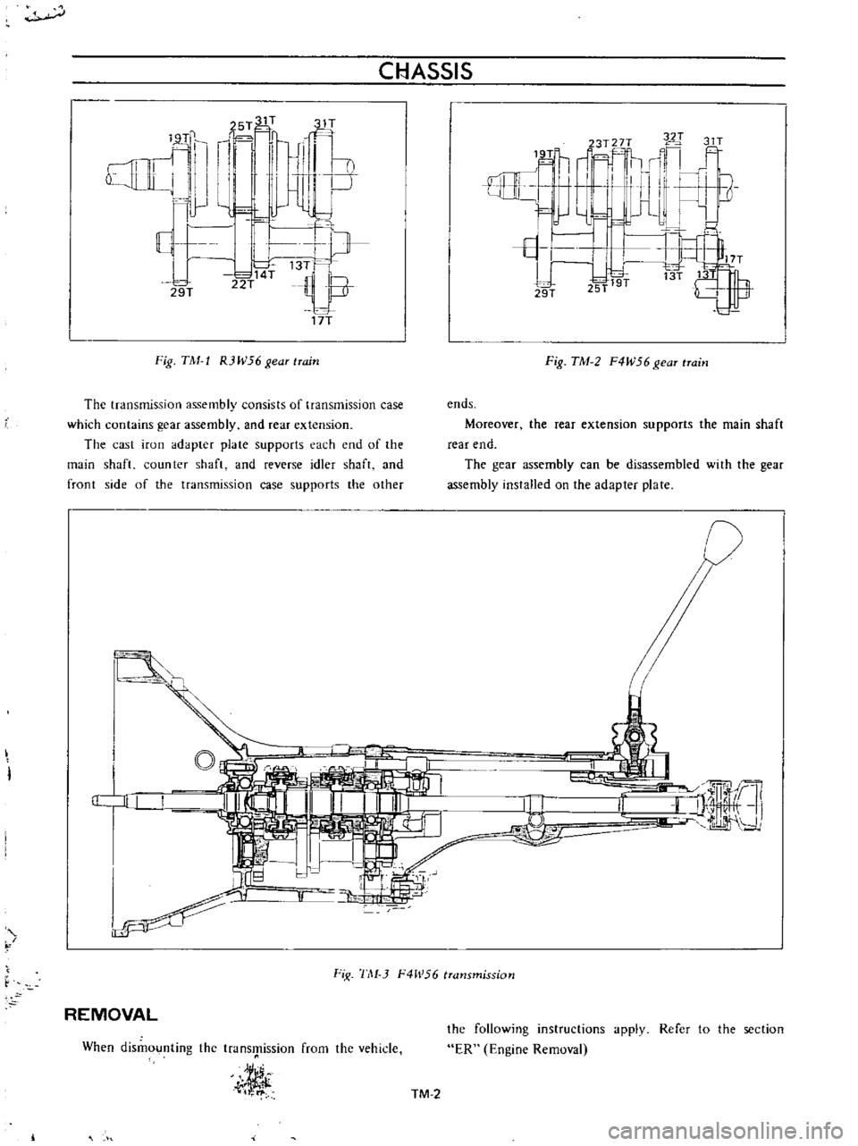
The
transmission
assembly
consists
of
transmission
case
which
contains
gear
assembly
and
rear
extension
The
cast
iron
adapter
plate
supports
each
end
of
the
main
shaft
counter
shaft
and
reverse
idler
shaft
and
front
side
of
the
transmission
case
supports
the
other
ends
Moreover
the
rear
extension
supports
the
main
shaft
rear
end
The
gear
assembly
can
be
disassembled
with
the
gear
assembly
installed
on
the
adapter
plate
j
I
a
JI
I
Ir
I
i
iiffq
J
1
f
Fi
1
1
1
J
F4h
56
transmission
REMOVAL
When
dismounting
the
transmission
from
the
vehicle
j
the
following
instructions
ER
Engine
Removal
apply
Refer
to
the
section
TM
2
Page 490 of 513
TRANSMISSION
I
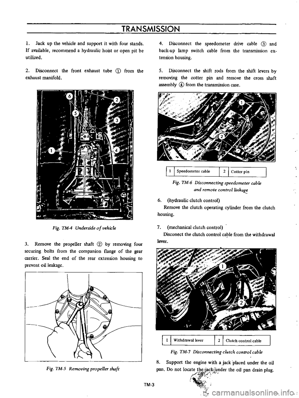
Jack
up
the
vehicle
and
support
it
with
four
stands
If
available
recommend
a
hydraulic
hoist
or
open
pit
be
utilized
2
Disconnect
the
front
exhaust
tube
D
from
the
exhaust
manifold
Fig
TM
4
Underside
of
vehiJ
1e
3
Remove
the
propeller
shaft
@
by
removing
four
securing
bolts
from
the
companion
flange
of
the
gear
carrier
Seal
the
end
of
the
rear
extension
housing
to
prevent
oil
leakage
Fig
TM
5
Removing
propeller
haft
4
Disconnect
the
speedometer
drive
cable
ID
and
back
up
lamp
switch
cable
from
the
transmission
ex
tension
housing
s
Disconnect
the
shift
rods
from
the
shift
levers
by
removing
the
cotter
pin
and
remove
the
cross
shaft
assembly
@
from
the
transmission
case
r
J
f
f
1
I
Speedometer
cable
I
2
I
Cotter
pin
Fig
TM
6
Disconnecting
speedometer
cable
and
remote
controllinkag
6
hydraulic
clutch
control
Remove
the
clutch
operating
cylinder
from
the
clutch
housing
7
mechanical
clutch
control
Disconect
the
clutch
control
cable
from
the
withdrawal
lever
1
1
Withdrawal
lever
2
I
Clutch
control
cable
Fig
TM
7
Disconnecting
clutch
control
cable
8
Support
the
engine
with
ajack
placed
under
the
oil
pan
Do
not
loca
1
f
nder
the
oil
pan
drain
plug
I
i
l
TM
3
Page 491 of 513
CHASSIS
To
prevent
the
oil
pan
from
damaging
insert
a
wooden
block
between
the
pan
and
jack
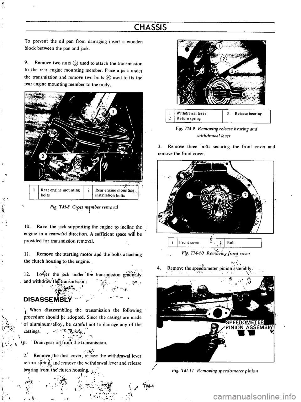
9
Remove
two
nuts
@
used
to
attach
the
transmission
to
the
rear
engine
mounting
member
Place
a
jack
under
the
transmission
and
remove
two
bolts
@
used
to
fix
the
rear
engine
mounting
member
to
the
body
It
I
Rear
engine
mou
ting
installation
bolts
I
Rear
engine
mounting
bolts
I
2
Fig
TM
8
C
oss
Fberremoval
10
Raise
the
jack
supporting
the
engine
to
incline
the
engine
in
a
rearward
direction
A
sufficient
space
will
be
provided
for
transmission
removal
I
Remove
the
starting
motor
a
d
the
bolts
attaching
the
clutch
housing
to
the
engine
12
Lower
the
jack
under
tlie
and
withdraw
thS
transmission
iJ
DISASSEMBI
Y
trans
fljssion
gradu3Ily
1
j
I
When
disassembling
the
transmission
the
following
procedure
sh
ould
pe
adopted
Since
the
casings
are
made
of
aluminum
alloy
be
careful
not
to
damage
any
of
the
castings
C
t
l
t1
Drain
gear
o
frqrP
the
transmission
I
2
Rc
ove
the
dust
cover
release
the
withdrawal
lever
n
turn
sprin
and
remove
the
withdrawal
lever
and
release
bC
lring
from
the
clutch
housing
h
IF
i
Iii
h
l
11
I
W
ithdrawallever
I
Return
spring
1
31
Release
bearing
Fig
TM
9
Removing
release
bearing
and
withdrawal
lever
3
Remove
three
bolts
securing
the
front
cover
and
remove
the
front
cover
II
I
Front
coveT
L
I
Bolt
Fig
TM
10
Remd
ving
fron
cover
4
Remove
the
spced
omcter
pinion
assembly
1f
SPEEDOMETER
PINION
ASSEMB
Y
w
Fig
TM
11
Removing
speedometer
pinion
TM
4
Page 496 of 513
TR
ANSMISSION
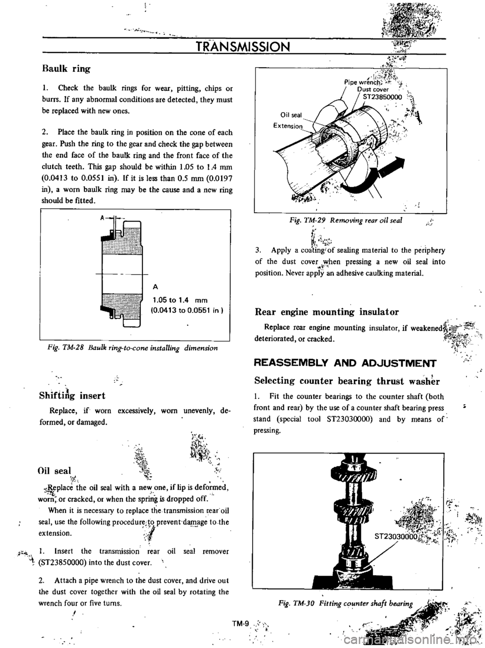
Baulk
ring
I
Check
the
baulk
rings
for
wear
pitting
chips
or
burrs
If
any
abnormal
conditions
are
detected
they
must
be
replaced
with
new
ones
2
Place
the
baulk
ring
in
position
on
the
cone
of
each
gear
Push
the
ring
to
the
gear
and
check
the
gap
between
the
end
face
of
the
bauIk
ring
and
the
front
face
of
the
clutch
teeth
This
gap
should
be
within
1
05
to
I
4
mm
0
0413
to
0
0551
in
If
it
is
less
than
0
5
mm
0
0197
in
a
worn
bauIk
ring
may
be
the
cause
and
a
new
ring
should
be
fitted
ii
V
ilillltII
l
A
1
05
to
1
4
mm
0
0413
to
0
0551
in
Fig
TM
28
ulk
ring
to
cone
installing
dimension
ShiftiAg
insert
Replace
if
worn
excessively
worn
unevenly
de
formed
or
damaged
Oil
seal
i
T
l
l
11
tT
Replace
the
oil
seal
with
a
new
one
if
lip
is
deformed
f
worn
or
cracked
or
when
the
spring
is
dropped
off
When
it
is
necessary
to
replace
the
transmission
rear
oil
seal
use
the
following
procedurecto
prevent
d
age
to
the
extension
l
1
Insert
the
transmission
rear
oil
seal
remover
ST23850000
into
the
dust
cover
2
Attach
a
pipe
wrench
to
the
dust
cover
and
drive
out
the
dust
cover
together
with
the
oil
seal
by
rotating
the
wrench
four
or
five
turns
I
Oil
seal
Extension
IJ
y
Fig
TM
29
Removing
rear
oil
seal
r
VI
1
3
Apply
a
coating
of
sealing
material
to
the
periphery
of
the
dust
cover
when
pressing
a
new
oil
seal
into
position
Never
apply
an
adhesive
caulking
material
Rear
engine
mounting
insulator
Replace
rear
engine
mounting
insulator
if
weakened
a
deteriorated
or
cracked
7i
1
rt
REASSEMBLY
AND
AD
JUSTMENT
Selecting
counter
bearing
thrust
washer
l
Fit
the
counter
bearings
to
the
counter
shaft
both
front
and
rear
by
the
use
of
a
counter
shaft
bearing
press
stand
special
tool
ST23030000
and
by
means
of
pressing
r
j
Itf
Fig
TM
JO
Fitting
counter
shaft
bearing
r
JJff
i
it
l
t
i
j
IlK
Ji
t
l
k
TM
9
Page 507 of 513
CHASSIS
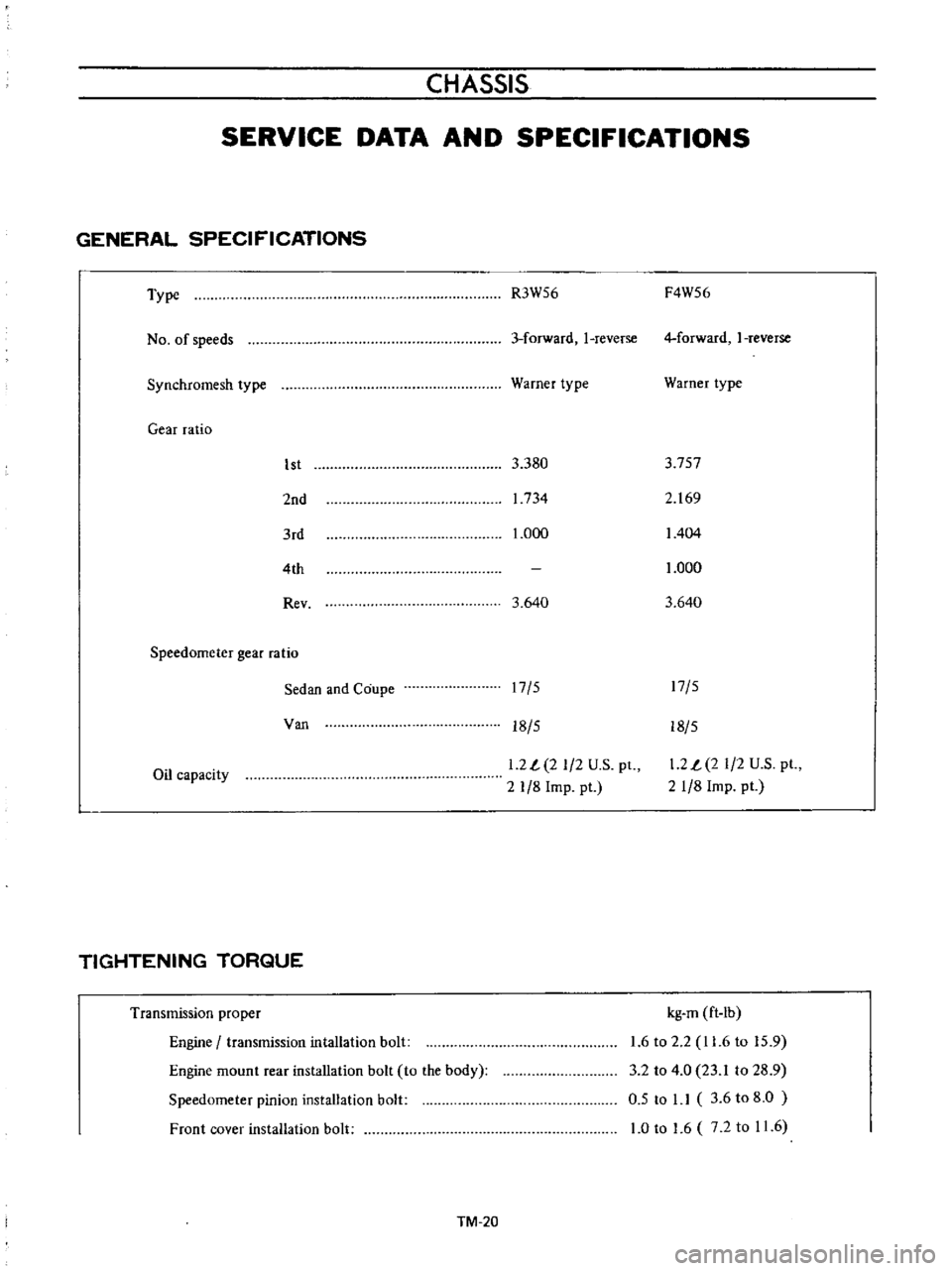
SERVICE
DATA
AND
SPECIFICATIONS
GENERAL
SPECIFICATIONS
Type
No
of
speeds
Synchromesh
type
Gear
ratio
1st
2nd
3rd
4th
Rev
Speedometer
gear
ratio
Sedan
and
Coupe
Van
Oil
capacity
TIGHTENING
TORQUE
Transmission
proper
Engine
transmission
intallation
bolt
Engine
mount
rear
installation
bolt
to
the
body
Speedometer
pinion
installation
bolt
Front
cover
installation
bolt
TM
20
R3W56
F4W56
3
forward
I
reverse
4
forward
I
reverse
Warner
type
Warner
type
3
380
3
757
1734
2
169
1
000
1404
1
000
3
640
3
640
17
5
17
5
18
5
18
5
1
2
L
2
1
2
U
S
pt
2
1
8
Imp
pt
1
2
L
2
1
2
U
S
pt
21
8
Imp
pt
kg
m
ft
Ib
1
6
to
2
2
11
6
to
15
9
3
2
to
4
0
23
1
to
28
9
0
5
to
1
1
3
6
to
8
0
1
0
to
1
6
7
2
to
11
6