check engine DATSUN PICK-UP 1977 Service Manual
[x] Cancel search | Manufacturer: DATSUN, Model Year: 1977, Model line: PICK-UP, Model: DATSUN PICK-UP 1977Pages: 537, PDF Size: 35.48 MB
Page 207 of 537
5
2
Checking
operation
of
duty
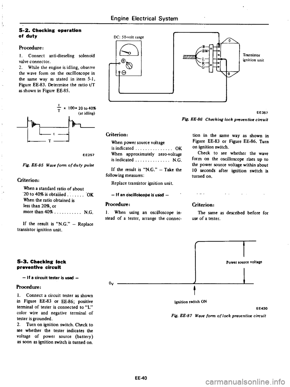
Procedure
Connect
anti
dieseling
solenoid
valve
connector
2
While
the
engine
is
idling
observe
the
wave
ronn
on
the
oscilloscope
in
the
same
way
as
stated
in
item
5
Figure
EE
83
Determine
the
ratio
tiT
as
shown
in
Figure
EE
85
I
T
x
100
20
to
401
1
at
idling
h
Lt
1
T
EE257
Fig
EE
85
Wove
form
ofduty
pulse
Criterion
When
a
standard
ratio
of
about
20
to
40
is
obtaiiied
OK
When
the
ratio
obtained
is
less
than
20
or
more
than
40
N
G
If
the
result
is
N
G
transistor
ignition
unit
Replace
5
3
Checking
lock
preventive
circuit
If
a
circuit
tester
is
used
Procedure
1
Connect
a
circuit
tester
as
shown
in
Figure
EE
83
or
EE
86
positive
terminal
of
tester
is
connected
to
L
color
wire
and
negative
terminal
of
tester
is
grounded
2
Turn
on
ignition
switch
Check
to
see
whether
the
tester
indicates
the
vol
age
of
power
source
ba
t1ery
as
soon
as
ignition
switch
is
turned
on
Engine
Electrical
System
DC
50
volt
range
rC
o
8
Criterion
When
power
source
voltage
is
indicated
When
approximately
is
indicated
OK
zero
voltage
N
G
If
the
result
is
N
G
Take
the
following
measures
Replace
transistor
ignition
unit
If
an
oscilloScope
is
uSetl
Procedure
I
When
using
an
oscilloscope
in
stead
of
a
tester
arrange
the
connec
Oy
EE
40
B
fJ
BW
O
L
t
1
V
Transi
tor
ignition
unit
EE357
Fig
EE
86
Checking
lock
p
uentive
circuit
tion
in
the
same
way
as
shown
in
Figure
EE
83
or
Figure
EE
86
Turn
on
ignition
switch
Check
to
see
whether
the
wave
form
on
the
oscilloscope
rises
up
to
the
power
source
voltage
within
about
10
seconds
after
ignition
switch
is
turned
on
Criterion
The
same
as
described
before
for
use
of
a
tester
Power
source
voltage
t
Ignition
switch
ON
EE430
Fig
EE
87
Wave
form
of
lock
preventive
circuit
Page 214 of 537
DESCRIPTION
INSPECTION
CLEANING
AND
REGAP
DESCRIPTION
The
spark
plugs
are
of
the
conven
tional
type
having
14
mm
0
551
in
threads
The
spark
plug
gaps
are
1
0
to
1
1
mm
0
039
to
0
043
in
on
Cali
fomia
models
and
0
8
to
0
9
mm
0
031
to
0
035
in
on
non
California
models
The
inspection
and
cleaning
should
be
made
every
suitable
mainte
nance
period
If
necessary
replace
Note
All
spark
plugs
installed
on
an
engine
must
be
of
the
same
brand
and
the
same
number
of
heat
range
INSPECTION
L
Remove
spark
plug
wire
by
pulling
on
boot
not
on
wire
itself
2
Remove
spark
plugs
3
Check
electrodes
and
inner
and
outer
porcelains
of
plugs
noting
the
type
of
deposits
and
the
degree
of
electrode
erosion
Refer
to
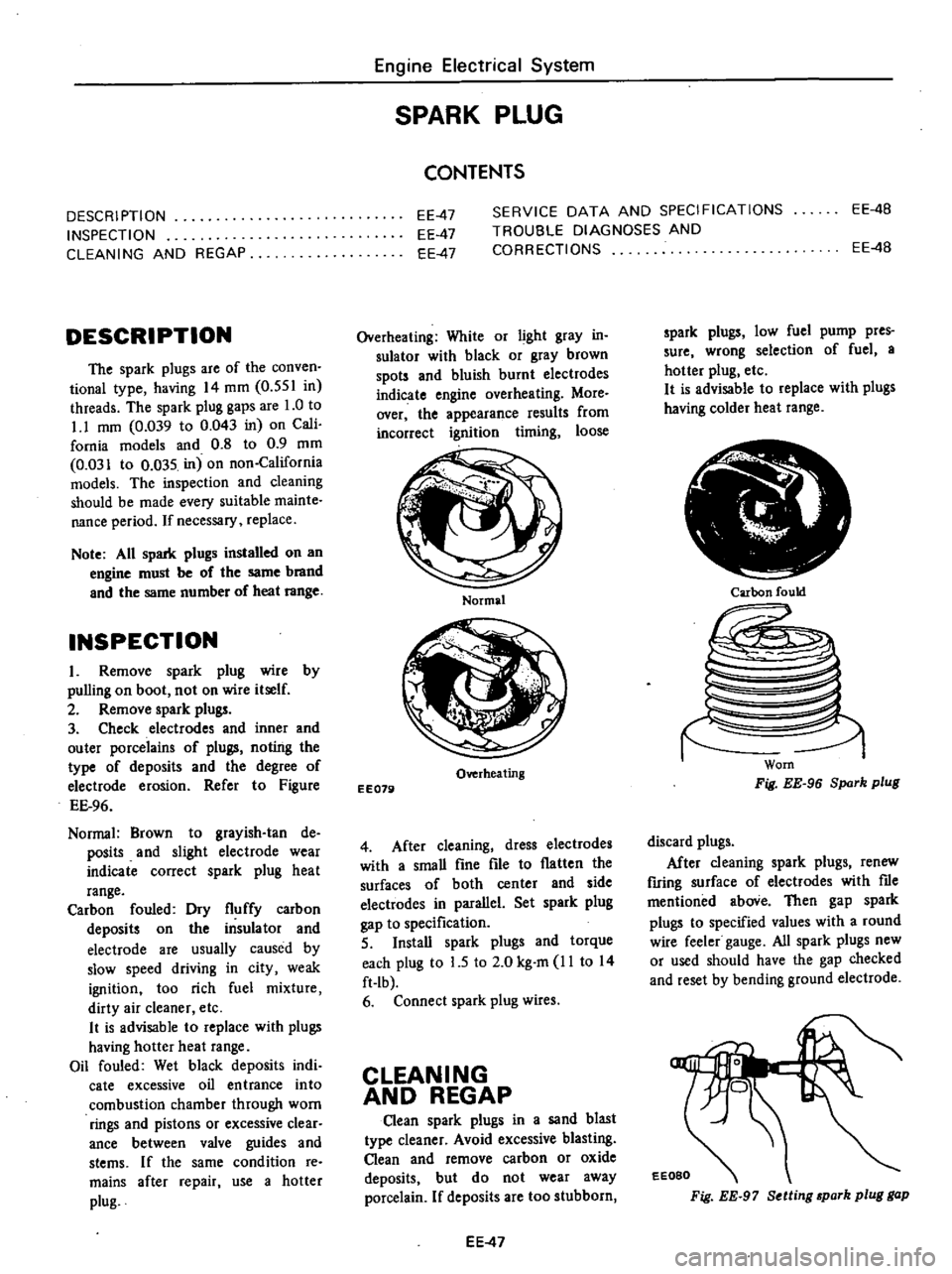
Figure
EE
96
Normal
Brown
to
grayish
tan
de
posits
and
slight
electrode
wear
indicate
correct
spark
plug
heat
range
Carbon
fouled
Dry
fluffy
carbon
deposits
on
the
insulator
and
electrode
are
usually
caused
by
slow
speed
driving
in
city
weak
ignition
too
rich
fuel
mixture
dirty
air
cleaner
etc
It
is
advisable
to
replace
with
plugs
having
hotter
heat
range
Oil
fouled
Wet
black
deposits
indi
cate
excessive
oil
entrance
into
combustion
chamber
through
worn
rings
and
pistons
or
excessive
clear
ance
between
valve
guides
and
stems
If
the
same
condition
re
mains
after
repair
use
a
hotter
plug
Engine
Electrical
System
SPARK
PLUG
CONTENTS
EE
4B
EE
47
EE
47
EE
47
SERVICE
DATA
AND
SPECIFICATIONS
TROUBLE
DIAGNOSES
AND
CORRECTIONS
EE
4B
Overheating
White
or
light
gray
in
sulator
with
black
or
gray
brown
spots
and
bluish
burnt
electrodes
indicate
engine
overheating
More
over
the
appearance
results
from
incorrect
ignition
timing
loose
Normal
Overheating
EE079
4
After
cleaning
dress
electrodes
with
a
smaU
fine
file
to
flatten
the
surfaces
of
both
center
and
side
electwdes
in
parallel
Set
spark
plug
gap
to
specification
5
InstaU
spark
plugs
and
torque
each
plug
to
L5
to
2
0
kg
m
11
to
14
ft
Ib
6
Connect
spark
plug
wires
CLEANING
AND
REGAP
Clean
spark
plugs
in
a
sand
blast
type
cleaner
Avoid
excessive
blasting
Clean
and
remove
carbon
or
oxide
deposits
but
do
not
wear
away
porcelain
If
deposits
are
too
stubborn
EE
47
spark
plugs
low
fuel
pump
pres
sure
wrong
selection
of
fuel
a
hotter
plug
etc
It
is
advisable
to
replace
with
plugs
having
colder
heat
range
Ir
i
Carbon
fould
Worn
Fig
EE
96
Spark
plug
discard
plugs
After
cleaning
spark
plugs
renew
firing
surface
of
electrodes
with
me
mentioned
aboVe
Then
gap
spark
plugs
to
specified
values
with
a
round
wire
feeler
gauge
All
spark
plugs
new
or
used
should
have
the
gap
checked
and
reset
by
bending
ground
electrode
EEOBO
Fig
EE
97
Setting
park
plug
gap
Page 215 of 537
Engine
Electrical
System
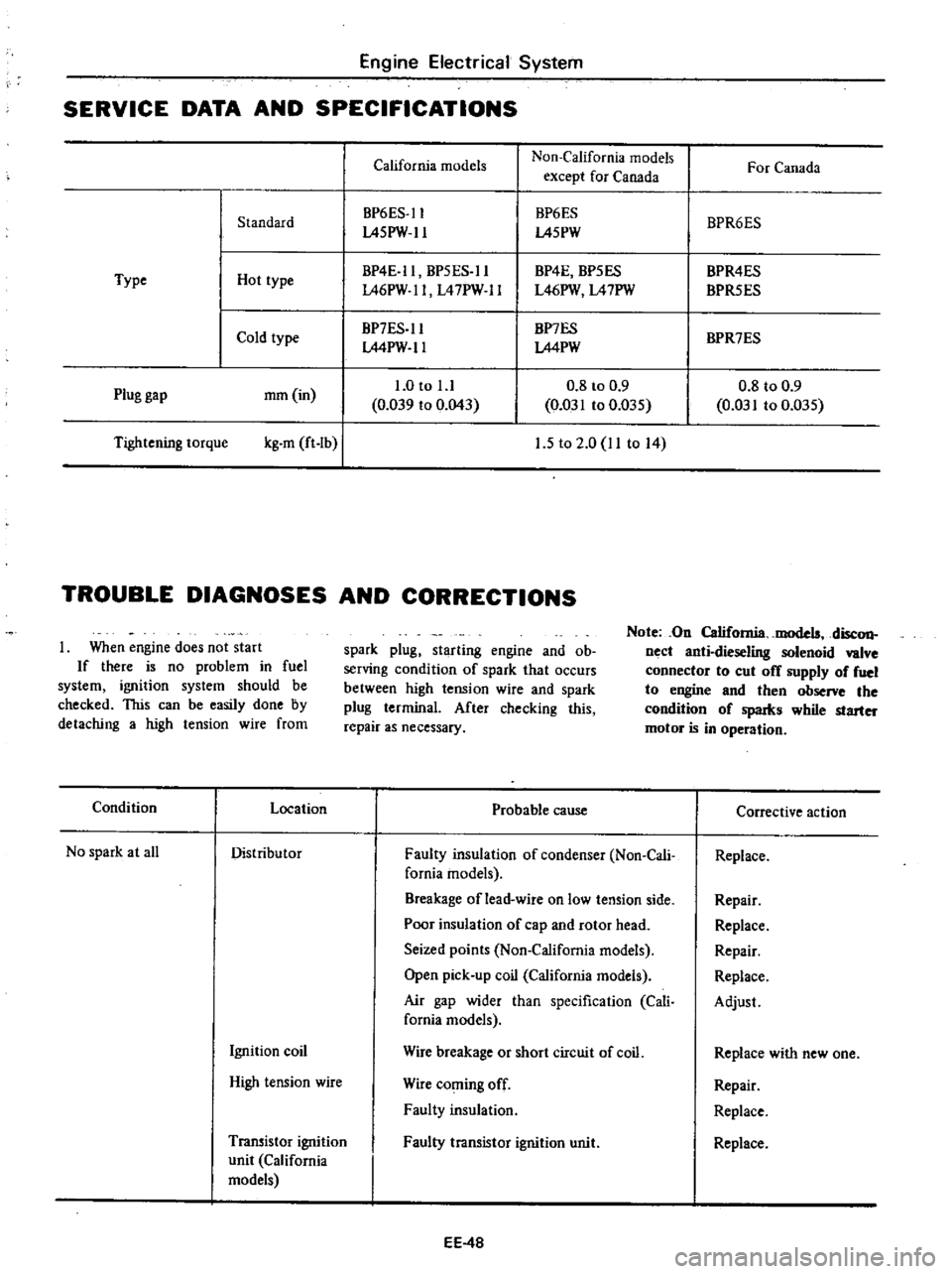
SERVICE
DATA
AND
SPECIFICATIONS
California
models
Non
California
models
For
Canada
except
for
Canada
BP6ES
ll
BP6ES
BPR6ES
Standard
L45PW
ll
L45PW
BP4E
ll
BP5ES
ll
BP4E
BP5ES
BPR4ES
Type
Hot
type
L46PW
ll
L47PW
ll
L46PW
L47PW
BPR5ES
Cold
type
BP7ES
ll
BP7ES
BPR7ES
LMPW
ll
LMPW
1
0
to
l
l
0
8
to
0
9
0
8
to
0
9
Plug
gap
mm
in
0
039
to
0
043
0
031
to
0
D35
0
031
to
0
035
Tightening
torque
kg
m
ft
Ib
I
1
5
to
2
0
11
to
14
TROUBLE
DIAGNOSES
AND
CORRECTIONS
When
engine
does
not
start
If
there
is
no
problem
in
fuel
system
ignition
system
should
be
checked
This
can
be
easily
done
by
detaching
a
high
tension
wire
from
spark
plug
starting
engine
and
ob
serving
condition
of
spark
that
occurs
between
high
tension
wire
and
spark
plug
terminal
After
checking
this
repair
as
necessary
Note
On
California
models
disc
on
nect
anti
dieseling
solenoid
valve
connector
to
cut
off
supply
of
fuel
to
engine
and
then
observe
the
condition
of
spaIks
while
starter
motor
is
in
operation
Condition
Location
Probable
cause
Corrective
action
No
spark
at
all
Distributor
Faulty
insulation
of
condenser
Non
Cali
Replace
fomia
models
Breakage
of
lead
wire
on
low
tension
side
Repair
Poor
insulation
of
cap
and
rotor
head
Replace
Seized
points
Non
California
models
Repair
Open
pick
up
coil
California
models
Replace
Air
gap
wider
than
specification
Cali
Adjust
fornia
models
Ignition
coil
Wire
breakage
or
short
circuit
of
coil
Replace
with
new
one
High
tension
wire
Wire
coming
off
Repair
Faulty
insulation
Replace
Transistor
ignition
Faulty
transistor
ignition
unit
Replace
unit
California
models
EE
4B
Page 225 of 537
l
t
tJ
I
P
o
CUll
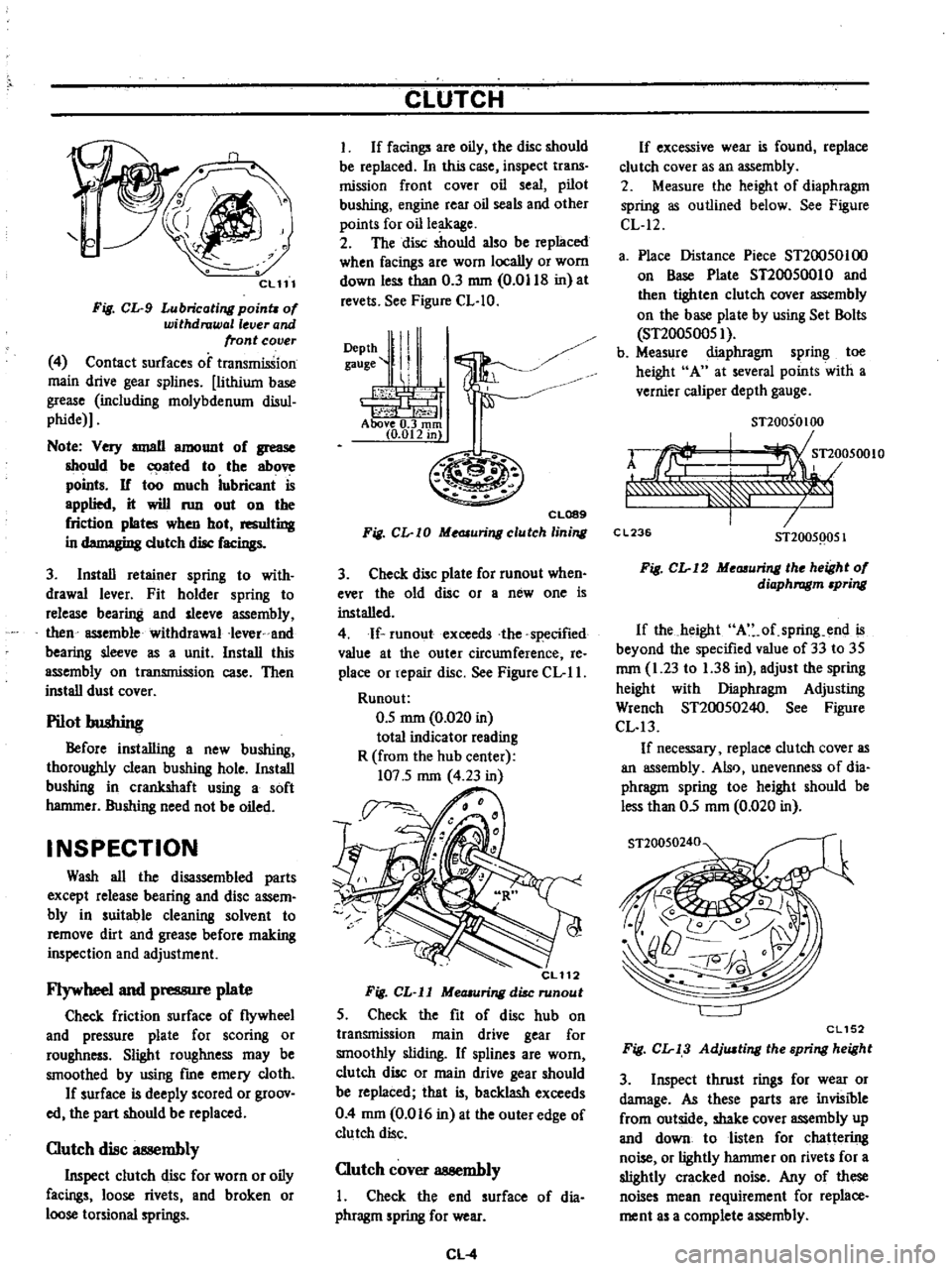
Fig
CL
9
Lubricating
poinu
of
withdrawal
lever
and
front
cover
4
Contact
surfaces
of
transmission
main
drive
gear
splines
lithium
base
grease
including
molybdenum
disul
phide
Note
Very
IIIIJllII
amount
of
grease
should
be
ated
to
the
above
points
If
too
much
iubricant
is
applied
it
will
run
out
on
the
friction
plates
when
hot
resulting
in
d
gi
dutch
disc
facings
3
Install
retainer
spring
to
with
drawal
lever
Fit
holder
spring
to
release
bearing
and
sleeve
assembly
then
assemble
withdrawal
Iever
and
bearing
sleeve
as
a
unit
Install
this
assembly
on
transmission
case
Then
install
dust
cover
Pilot
bushing
Before
installing
a
new
bushing
thoroughly
clean
bushing
hole
Install
bushing
in
crankshaft
using
a
soft
hammer
Bushing
need
not
be
oiled
INSPECTION
Wash
all
the
disassembled
parts
except
release
bearing
and
disc
assem
bly
in
suitable
cleaning
solvent
to
remove
dirt
and
grease
before
making
inspection
and
adjustment
Flywheel
and
pressure
plate
Check
friction
surface
of
flywheel
and
pressure
plate
for
scoring
or
roughness
Slight
roughness
may
be
smoothed
by
using
fme
emery
cloth
If
surface
is
deeply
scored
or
groov
ed
the
part
should
be
replaced
Clutch
disc
at
llembly
Inspect
clutch
disc
for
worn
or
oily
facings
loose
rivets
and
broken
or
loose
torsional
springs
CLUTCH
I
If
facings
are
oily
the
disc
should
be
replaced
In
this
case
inspect
trans
mission
front
cover
oil
seal
pilot
bushing
engine
rear
oil
seals
and
other
points
for
oil
leakage
2
The
disc
should
also
be
replaced
when
facings
are
worn
locally
or
worn
down
less
than
0
3
mm
0
0118
in
at
revels
See
Figure
CL
IO
DePth
ll
I
gauge
II
1
i
h
1
j1
t
f
Above
0
3
rom
10
012
in
CL089
Fig
CL
I0
Me
JIuringclutch
lining
3
Check
disc
plate
for
runout
when
ever
the
old
disc
or
a
new
one
is
installed
4
If
runoutexceeds
the
specified
value
at
the
outer
circumference
Ie
place
or
repair
disc
See
Figure
CL
II
Runou
t
0
5
mm
0
020
in
total
indicator
reading
R
from
the
hub
center
107
5
mm
4
23
in
CL112
Fig
CL
ll
MeOlUring
disc
runout
5
Check
the
fit
of
disc
hub
on
transmission
main
drive
gear
for
smoothly
sliding
If
splines
are
worn
clutch
disc
or
main
drive
gear
should
be
replaced
that
is
backlash
exceeds
0
4
mm
0
016
in
at
the
outer
edge
of
clutch
disc
Clutch
cover
assembly
I
Check
the
end
surface
of
dia
phragm
spring
for
wear
CL
4
If
excessive
wear
is
found
replace
clu
tch
cover
as
an
assembly
2
Measure
the
height
of
diaphragm
spring
as
outlined
below
See
Figure
CL
12
a
Place
Distance
Piece
ST20050100
on
Base
Plate
ST20050010
and
then
tighten
clutch
cover
assembly
on
the
base
plate
by
using
Set
Bolls
ST20050051
b
Measure
diaphragm
spring
toe
height
A
at
several
points
with
a
vernier
caliper
depth
gauge
STl0050100
rJrf
I
Tl
05001O
f
7
C
L23
STl005Q051
Fig
CL
12
Me
uring
the
height
of
diaphragm
pring
If
the
height
A
of
spring
end
is
beyond
the
specified
value
of
33
to
35
mm
1
23
to
1
38
in
adjust
the
spring
height
with
Diaphragm
Adjusting
Wrench
ST20050240
See
Figure
CL
13
If
necessary
replace
clutch
cover
as
an
assembly
Also
unevenness
of
dia
phragm
spring
toe
height
should
be
less
than
05
mm
0
020
in
ST20050240
CL152
Fig
CL
13
AdjlUting
the
spring
height
3
Inspect
thrust
rings
for
wear
or
damage
As
these
parts
are
invisible
from
outside
shake
cover
assembly
up
and
down
to
listen
for
chattering
noise
or
lightly
hammer
on
rivets
for
a
slightly
cracked
noise
Any
of
these
noises
mean
requirement
for
replace
ment
as
a
complete
assembly
Page 231 of 537
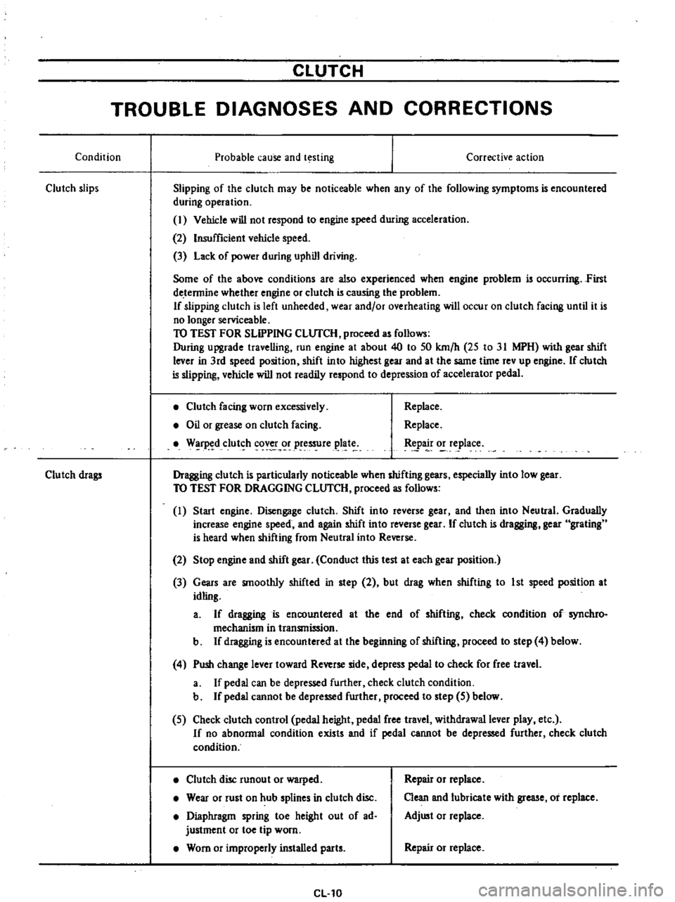
CLUTCH
TROUBLE
DIAGNOSES
AND
CORRECTIONS
Condition
Probable
cause
and
testing
Clutch
slips
Corrective
action
Slipping
of
the
clutch
may
be
noticeable
when
any
of
the
following
symptoms
is
encountered
during
operation
I
Vehicle
will
not
respond
to
engine
speed
during
acceleration
2
Insufficient
vehicle
speed
3
Lack
of
power
during
uphill
driving
Some
of
the
above
conditions
are
also
experienced
when
engine
problem
is
oc
urring
First
de
tennine
whether
engine
or
clutch
is
causing
the
problem
If
slipping
clutch
is
left
unheeded
wear
and
or
overheating
will
occur
on
clutch
facing
until
it
is
no
longer
serviceable
TO
TEST
FOR
SLIPPING
CLlJfCH
proceed
as
follows
During
upgrade
travelling
run
engine
at
about
40
to
50
km
h
25
to
31
MPH
with
gear
shift
lever
in
3rd
speed
position
shift
into
highest
gear
and
at
the
same
time
rev
up
engine
If
clutch
is
slipping
vehicle
will
not
readily
respond
to
depression
of
accelerator
pedal
Clutch
facing
worn
excessively
Oil
or
grease
on
clutch
facing
W
r
d
clut
h
cov
r
pressure
plat
Replace
Replace
tpa
o
e
lace
Dragging
clutch
is
particularly
noticeable
when
shifting
gears
especially
into
low
gear
TO
TEST
FOR
DRAGGING
CLlJfCH
proceed
as
follows
I
Start
engine
Disengage
clutch
Shift
into
reverse
gear
and
then
into
Neutral
Gradually
increase
engine
speed
and
again
shift
into
reverse
gear
If
clutch
is
dragging
gear
grating
is
heard
when
shifting
from
Neutral
into
Reverse
Clutch
drags
2
Stop
engine
and
shift
gear
Conduct
this
test
at
each
gear
position
3
Gears
are
smoothly
shifted
in
step
2
but
drag
when
shifting
to
1st
speed
position
at
idling
a
If
dragging
is
encountered
at
the
end
of
shifting
check
condition
of
synchro
mechanism
in
transmission
b
If
dragging
is
encountered
at
the
beginning
of
shifting
proceed
to
step
4
below
4
Push
change
lever
toward
Reverse
side
depress
pedal
to
check
for
free
travel
a
If
pedal
can
be
depressed
further
check
clutch
condition
b
If
pedal
cannot
be
depressed
further
proceed
to
step
5
below
5
Check
clutch
control
pedal
height
pedal
free
travel
withdrawal
lever
play
etc
If
no
abnonnal
condition
exists
and
if
pedal
cannot
be
depressed
further
check
clutch
condition
Clutch
disc
runout
or
warped
Wear
or
rust
on
hub
splines
in
clutch
disc
Diaphragm
spring
toe
height
out
of
ad
justment
or
toe
tip
worn
Worn
or
improperly
installed
parts
CL10
Repair
or
replace
Clean
and
lubricate
with
grease
or
replace
Adjust
or
replace
Repair
or
replace
Page 242 of 537
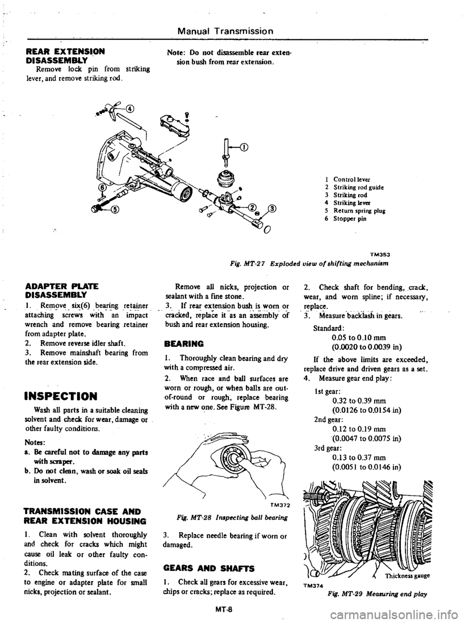
REAR
EXTENSION
DISASSEMBLY
Remove
lock
pin
from
striking
lever
and
remove
striking
rod
Manual
Transmission
Note
00
not
diSlssemble
rear
exten
sion
bush
from
rear
extension
ADAPTER
PLATE
DISASSEMBLY
I
Remove
six
6
bearing
retainer
attaching
screws
with
an
impact
wrench
and
remove
bearing
retainer
from
adapter
plate
2
Remove
reverse
idler
shaft
3
Remove
mainshaft
bearing
from
the
rear
extension
side
INSPECTION
Wash
all
parts
in
a
suitable
cleaning
solvent
and
check
for
wear
damage
or
other
faulty
conditions
Notes
a
Be
careful
not
to
damage
any
parts
with
scraper
b
00
not
clean
wash
or
soak
oil
seals
in
solvent
TRANSMISSION
CASE
AND
REAR
EXTENSION
HOUSING
I
Clean
with
solvent
thoroughly
and
check
for
cracks
which
might
cause
oil
leak
or
other
faulty
con
ditions
2
Check
mating
surface
of
the
case
to
engine
or
adapter
plate
for
small
nicks
projection
or
sealant
e
1
Control
lever
2
Striking
rod
guide
3
Striking
rod
4
Striking
lever
5
Return
spring
plug
6
Stopper
pin
TM353
Fig
MT
27
Exploded
view
of
shifting
mechani6m
Remove
all
nicks
projection
or
sealant
with
a
frne
stone
3
If
rear
extension
bush
is
worn
or
cracked
replace
it
as
an
assembly
of
bush
and
rear
extension
housing
BEARING
I
Thoroughly
clean
bearing
and
dry
with
a
compressed
air
2
When
race
and
ball
surfaces
are
worn
or
rough
or
when
balls
are
out
of
round
or
rough
replacebearihg
with
a
new
one
See
Figure
MT
28
I
TM372
Fig
MT
28
l
pecting
ball
bearing
3
Replace
needle
bearing
if
worn
or
damaged
GEARS
AND
SHAFTS
I
Check
all
gears
for
excessive
wear
chips
or
cracks
replace
as
required
MT
8
2
Check
shaft
for
bending
crack
wear
and
worn
spline
if
necessary
replace
3
Measure
backiasii
in
gears
Standard
0
05
to0
10mm
0
0020
to
0
0039
in
If
the
above
limits
are
exceeded
replace
drive
and
driven
gears
as
a
set
4
Measure
gear
end
play
1st
gear
0
32
to
0
39
mm
0
0126
to
0
0154
in
2nd
gear
0
12
to
0
19
mm
0
0047
to
0
0075
in
3rd
gear
0
13
to
0
37
mm
0
0051
to
0
0146
in
TM374
Fig
MT
29
Measuring
end
play
Page 256 of 537
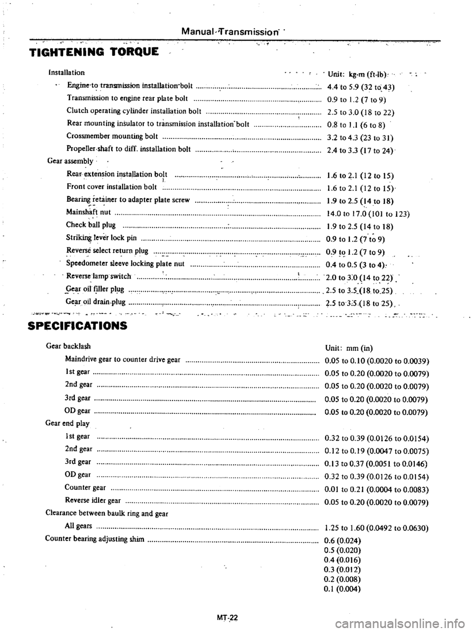
Manual
iTransmission
TIGHTENING
TORQUE
Installa
tion
Engine
to
transmission
installation
bolt
Transmission
to
engine
rear
plate
bolt
Clutch
operating
cylinder
installation
bolt
Rear
mounting
insulator
to
transmission
installation
bolt
Crossmember
mounting
bolt
Propeller
shaft
to
diff
installation
bolt
Gear
assembly
Rear
extension
installation
bolt
Front
cover
installation
bolt
Bearing
retainer
to
adapter
plate
screw
Main
haft
nut
Check
ball
plug
Stri
lever
lock
pin
Reverse
select
return
plug
Speedometer
sleeve
locking
plate
nut
Reverse
lamp
switch
year
oil
Ier
pl
g
Ge
r
oil
drain
plug
Unit
kg
m
ft
lb
4
4
to
5
9
32
to
43
0
9
to
1
2
7
to
9
2
5
to
3
0
18
to
22
0
8
to
1
1
6
to
8
3
2
to
43
23
to
31
2
4
to
33
17
to
24
1
6
to
2
1
12
to
IS
1
6
to
2
1
12to
IS
1
9
to
2
S
14
to
18
14
0
to
17
0
101
to
123
1
9
to
2
S
14
to
18
0
9
to
1
2
7
to
9
0
9
1
2
7
to
9
0
4
to
O
S
3
to
4
2
0
to
3
0
14
to
22
2
S
to
3
5
18
t02S
2
S
toTS
l8
to
2S
or
SPECIFICATIONS
Gear
backlash
Maindrive
gear
to
counter
drive
gear
1st
gear
2nd
gear
3rd
gear
OD
gear
Gear
end
play
1st
gear
2nd
gear
3rd
gear
OD
gear
Counter
gear
Reverse
idler
gear
Clearance
between
baulk
ring
and
gear
All
gears
Counter
bearing
adjusting
shim
Unit
mm
in
0
05
to
0
10
0
0020
to
0
0039
0
05
to
0
20
0
0020
to
0
0079
O
OS
to
0
20
0
0020
to
0
0079
0
05
to
0
20
0
0020
to
0
0079
0
05
to
0
20
0
0020
to
0
0079
0
32
to
0
39
0
0126
to
0
0154
0
12
to
0
19
0
0047
to
0
0075
0
13
to
0
37
0
0051
to
0
0146
0
32
to
0
39
0
0126
to
0
0154
0
01
to
0
21
0
0004
to
0
0083
0
05
to
0
20
0
0020
to
0
0079
1
25
to
1
60
0
0492
to
0
0630
0
6
0
024
0
5
0
020
0
4
0
016
0
3
0
012
0
2
0
008
0
1
0
004
MT
22
Page 257 of 537
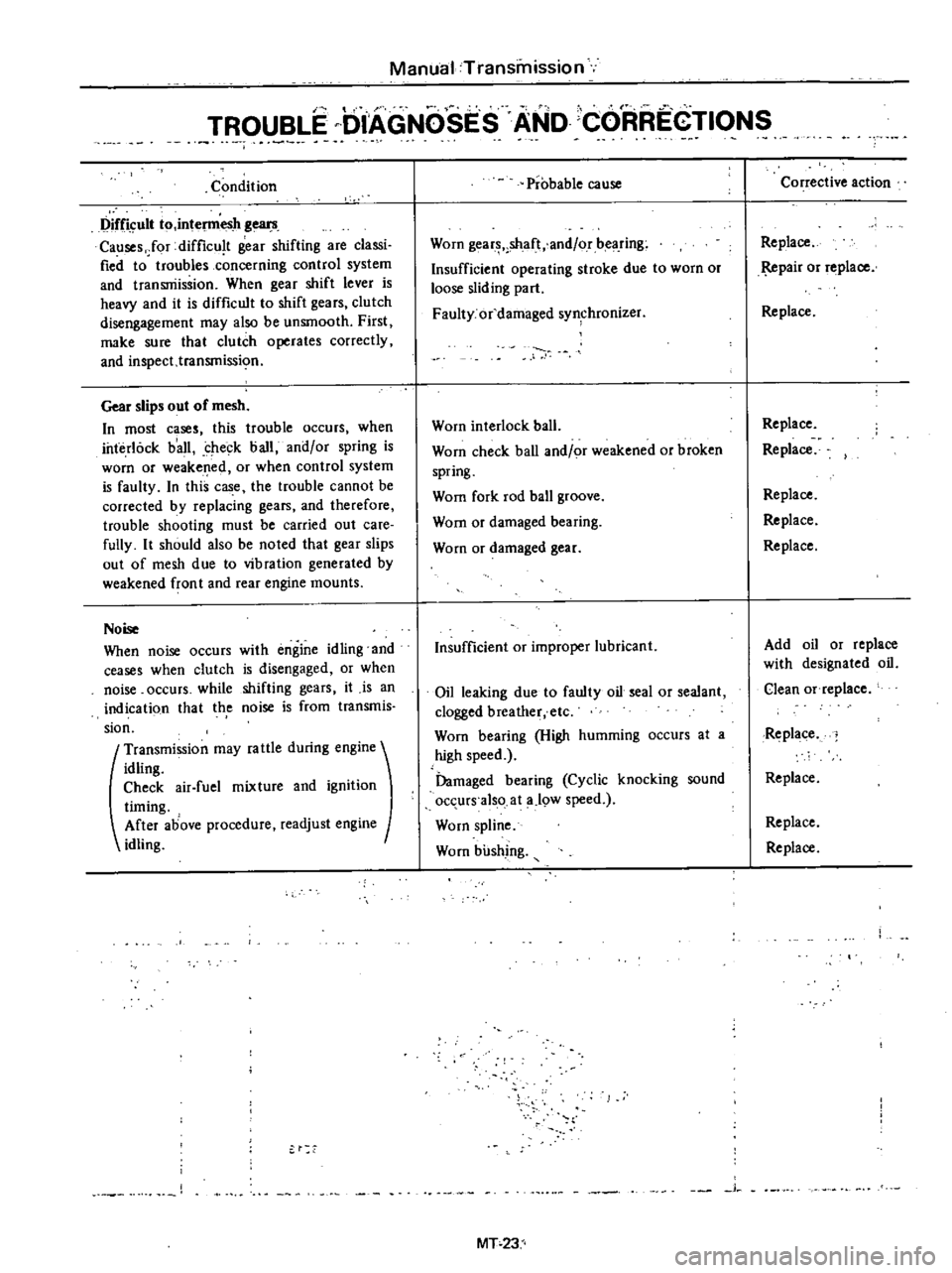
Manual
Transmission
I
TROUBLE
DIAGNOSES
AND
CORREGTIONS
Condition
Difficult
to
intel11lesh
gears
Causes
Jor
difficu
t
gear
shifting
are
classi
fied
to
troubles
concerning
control
system
and
transniissioo
When
gear
shift
lever
is
heavy
and
it
is
difficult
to
shift
gears
clutch
disengagement
may
also
be
unsmooth
First
make
sure
that
clutch
operates
correctly
and
inspect
transmissi
o
Gear
slips
out
of
mesh
In
most
cases
this
trouble
occurs
when
interlock
b
all
check
ball
and
or
spring
is
worn
or
weakened
or
when
control
system
is
faulty
In
this
case
the
trouble
cannot
be
corrected
by
replacing
gears
and
therefore
trouble
shooting
must
be
carried
out
care
fully
It
should
also
be
noted
that
gear
slips
out
of
mesh
due
to
vibration
generated
by
weakened
fron
t
and
rear
engine
mounts
Noise
When
noise
occurs
with
engine
idling
and
ceases
when
clutch
is
disengaged
or
when
noise
occurs
while
shifting
gears
it
is
an
indicati90
that
th
e
noise
is
from
transmis
sion
t
Transmission
may
fa
ule
during
engine
idling
Check
air
fuel
mixture
and
ignition
timing
After
above
procedure
readjust
engine
idling
Probable
cause
Worn
gear
shaft
and
or
bearing
Insufficient
operating
stroke
due
to
worn
or
loose
sliding
part
Faulty
or
damaged
synchronizer
Worn
interlock
ball
Worn
check
ball
and
or
weakened
or
broken
spring
Wom
fork
rod
ball
groove
Wom
or
damaged
bearing
Worn
or
damaged
gear
Insufficient
or
improper
lubricant
Oil
leaking
due
to
faulty
oil
seal
or
sealant
clogged
breather
etc
Worn
bearing
High
humming
occurs
at
a
high
speed
Damaged
bearing
Cyclic
knocking
sound
occurs
also
at
a
19W
speed
Worn
spline
Worn
bushing
j
MT
23
Corrective
action
Replace
pair
or
replace
Replace
Replace
Replace
Replace
Replace
Replace
Add
oil
or
replace
with
designated
oil
Clean
Of
replace
Replace
Replace
Replace
Replace
Page 298 of 537
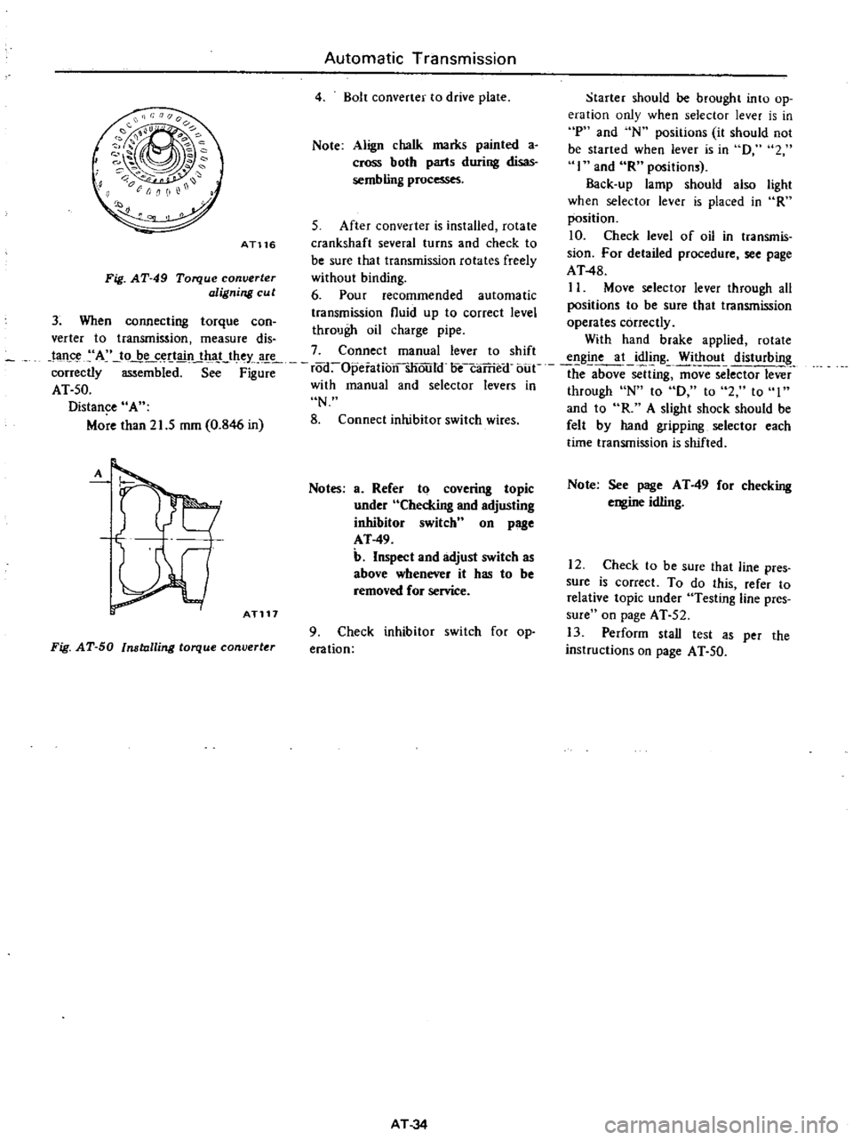
Starter
should
be
brought
into
op
eration
only
when
selector
lever
is
in
P
and
N
positions
it
should
not
be
started
when
lever
is
in
D
2
I
and
R
positions
Back
up
lamp
should
also
light
when
selector
lever
is
placed
in
R
position
S
After
converter
is
installed
rotate
10
Check
level
of
oil
in
transmis
crankshaft
several
turns
and
check
to
be
sure
that
transmission
rotates
freely
sion
For
detailed
procedure
see
page
AT48
without
binding
6
Pour
recommended
automatic
II
Move
selector
lever
through
aU
positions
to
be
sure
that
transmission
transmission
fluid
up
to
correct
level
operates
correctly
through
oil
charge
pipe
verter
to
transmission
measure
dis
With
hand
brake
applied
rotate
tan
A
to
be
certain
that
they
are
7
Connect
manual
lever
to
shift
engine
at
idling
Without
disturbing
correctly
mbi
d
S
F
rod
Opeiationsliould
oecaTrie
f
bue
the
above
sclUng
ffiovTSelector
lever
AT
50
with
manual
and
selector
levers
in
through
N
to
D
to
2
to
I
Distance
A
N
and
to
R
A
slight
shock
should
be
More
than
21
5
mm
0
846
in
8
Connect
inhibitor
switch
wires
felt
by
hand
gripping
selector
each
time
transmission
is
shifted
Automatic
Transmission
4
Bolt
converter
to
drive
plate
Note
Align
chalk
marks
painted
a
cross
both
parts
during
disas
sembling
processes
AT116
Fig
AT
49
Torque
converter
aligning
cu
t
3
When
connecting
torque
can
A
ATl17
Notes
a
Refer
to
covering
topic
under
Checking
and
adjusting
inhibitor
switch
n
on
page
AT
49
b
Inspect
and
adjust
switch
as
above
whenever
it
has
to
be
removed
for
service
Fig
AT
50
Installing
torque
converter
9
Check
inhibitor
switch
for
op
eration
AT
34
Note
See
page
AT
49
for
checking
engine
idling
12
Check
to
be
sure
that
line
pres
sure
is
correct
To
do
this
refer
to
relative
topic
under
Testing
line
pres
sure
on
page
AT
52
13
Perform
stall
test
as
per
the
instructions
on
page
AT
50
Page 300 of 537
Automatic
Transmission
MAJOR
REPAIR
OPERATION
SERVICE
NOTICE
FOR
DISASSEMBLY
AND
ASSEMBLY
TORQUE
CONVERTER
INSPECTION
TRANSMISSION
DISASSEMBL
Y
INSPECTION
ASSEMBL
Y
SERVICE
NOTICE
FOR
DISASSEMBLY
AND
ASSEMBLY
I
It
is
advisable
that
repair
opera
tions
be
carried
out
in
a
dust
proof
room
2
Due
to
the
differences
of
the
engine
capacities
the
specifications
of
component
parts
for
each
model
s
transmission
may
be
different
They
do
however
have
common
adjust
ment
and
repair
procedures
as
well
as
cleaning
and
inspection
procedures
outlined
hereinafter
3
During
repair
operations
refer
to
Service
Data
and
Specifications
see
tion
for
the
correct
parts
for
each
model
4
Before
removing
any
of
subas
semblies
thoroughly
clean
the
outside
of
the
transmission
to
prevent
dirt
from
entering
the
mechanical
parts
5
Do
not
use
a
waste
rag
Use
a
nylon
or
paper
cloth
6
After
disassembling
wash
all
dis
assembled
parts
and
examine
them
to
see
if
there
are
any
worn
damaged
or
defective
parts
and
how
they
are
affected
Refer
to
Service
Data
for
the
extent
of
damage
that
justifies
replacement
7
As
a
rule
packings
seals
and
similar
parts
once
disassembled
should
be
replaced
with
new
ones
TORQUE
CONVERTER
The
torque
converter
is
a
welded
construction
and
can
not
be
disas
sembled
CONTENTS
AT
36
AT
36
AT
36
AT
36
AT
36
AT
38
AT
38
COMPONENT
PARTS
FRONT
CLUTCH
REAR
CLUTCH
LOW
REVERSE
BRAKE
SERVO
PISTON
GOVERNOR
OIL
PUMP
PLANETARY
CARRIER
CONTROL
VALVE
AT
40
AT
40
AT
41
AT
42
AT
42
AT
43
AT
43
AT
44
AT
44
INSPECTION
2
Remove
bolts
securing
converter
1
Check
torque
convertf
for
any
housing
to
transmission
case
Remove
sign
of
damage
bending
oil
leak
or
torque
converter
deformation
If
necessary
replace
3
Remove
speedometer
pinion
2
Remove
rust
from
pilots
and
sleeve
bolt
Withdraw
pinion
bosses
completely
4
Remove
downshift
solenoid
and
If
torque
converter
oil
is
fouled
or
vacuum
diaphragm
Do
not
leave
dia
contaminated
due
to
burnt
clutch
phragm
rod
at
this
stage
of
disas
flush
the
torque
converter
as
follows
sembly
Rod
is
assembled
in
top
of
vacuum
diaphragm
See
Figure
I
Drain
oil
in
torque
converter
AT
53
2
Pour
non
lead
gasoline
or
kero
sene
into
torque
converter
approxi
mately
0
5
liter
I
U
S
pt
U
Imp
pt
3
Blow
air
into
torque
converter
and
flush
and
drain
out
gasoline
4
Fill
torque
converter
with
torque
converter
oil
approximately
0
5
liter
I
V
S
pt
U
Imp
pt
5
Again
blow
air
into
torque
con
verter
and
drain
torque
converter
oil
TRANSMISSION
DISASSEMBLY
I
Drain
oil
from
the
end
of
rear
extension
Mount
transmission
on
Transmission
Case
Stand
ST07870000
or
ST07860000
Remove
oil
pan
See
Figure
AT
52
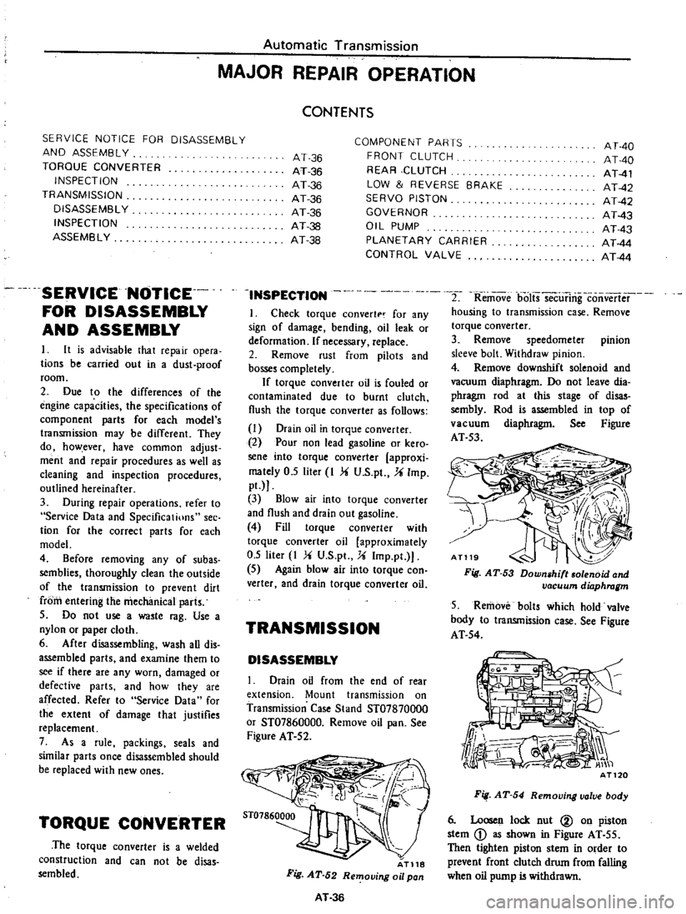
AT118
Fig
AT
52
Removing
oil
pan
AT
36
Fig
AT
53
Down
hilt
olenoid
and
vacuum
dilJphragm
5
Remove
bolts
which
hold
valve
body
to
transmission
case
See
Figure
AT
54
Fig
AT
54
Removing
valve
body
6
Loosen
lock
nut
@
on
piston
stem
D
as
shown
in
Figure
AT
55
Then
tighten
piston
stem
in
order
to
prevent
front
clutch
drum
from
falling
when
oil
pump
is
withdrawn