check engine DATSUN PICK-UP 1977 Manual PDF
[x] Cancel search | Manufacturer: DATSUN, Model Year: 1977, Model line: PICK-UP, Model: DATSUN PICK-UP 1977Pages: 537, PDF Size: 35.48 MB
Page 130 of 537
CLEANING
AND
INSPECTION
Dirt
gum
wuler
or
l
arbon
con
taminatiun
in
or
on
exterior
moving
parts
of
a
arburctor
arc
often
respon
sihk
for
unsatisfactory
performance
For
this
reason
efficient
carbutetioll
dcpends
upon
careful
cleaning
and
inspection
while
servicing
I
Blow
all
passages
and
castings
with
compressed
air
and
blow
off
all
parts
until
dry
Note
Do
not
pass
drills
or
wires
through
calibrated
jet
or
passaaa
as
this
may
enlarge
orirlce
and
seriously
affect
carburetor
calibrs
lion
2
Check
all
parts
for
wear
If
wear
is
noted
damaged
parts
must
be
re
placed
Note
especially
the
following
Engine
Fuel
I
Check
float
needle
and
seat
for
wear
If
wear
is
noted
assembly
must
be
replaced
2
Check
throule
and
choke
shaft
bores
in
throtlle
chamber
and
choice
chamber
for
wear
or
out
of
roundness
3
Inspect
idle
adjusting
needle
for
burrs
or
ridges
Such
a
condition
re
quires
replacemen
1
3
Inspect
gaskets
0
see
if
they
appear
hard
or
briUle
or
if
edges
are
torn
or
distorted
If
any
such
condi
tion
i
noted
they
must
be
replaced
4
Check
filter
screen
for
dirt
or
lint
Clean
and
if
screen
is
distorted
or
remain
plugged
replace
5
Check
linkage
for
operating
condition
6
Inspect
operation
of
accelerating
pump
Pour
f
el
into
jloat
chamber
and
make
throtlle
lever
operate
Check
condition
of
fuel
injection
from
the
EF
34
accelerating
nowe
7
Push
connecting
rod
of
dia
phragm
chamber
and
block
passage
of
vacuum
with
finger
When
connecting
rod
becomes
free
check
for
leakage
of
air
or
damage
to
diaphragm
Jets
Carburetor
performance
depends
on
jet
and
air
bleed
That
is
why
these
components
must
be
fabricated
with
utmost
care
To
clean
them
use
cleaning
solvent
and
blow
air
on
them
Larger
inner
numbers
tamped
on
the
jet
indicate
larger
diameters
Ac
cordingly
main
and
slow
jets
with
lalger
nUmbers
provide
richer
mixture
the
smaller
the
numbers
the
leaner
the
mixture
Conversely
the
main
and
slow
air
bleeds
through
which
air
to
passes
through
make
the
fueLleaner
if
they
bear
larger
numbers
the
smaller
the
numbers
the
richer
the
fuel
Page 132 of 537
Engine
Fuel
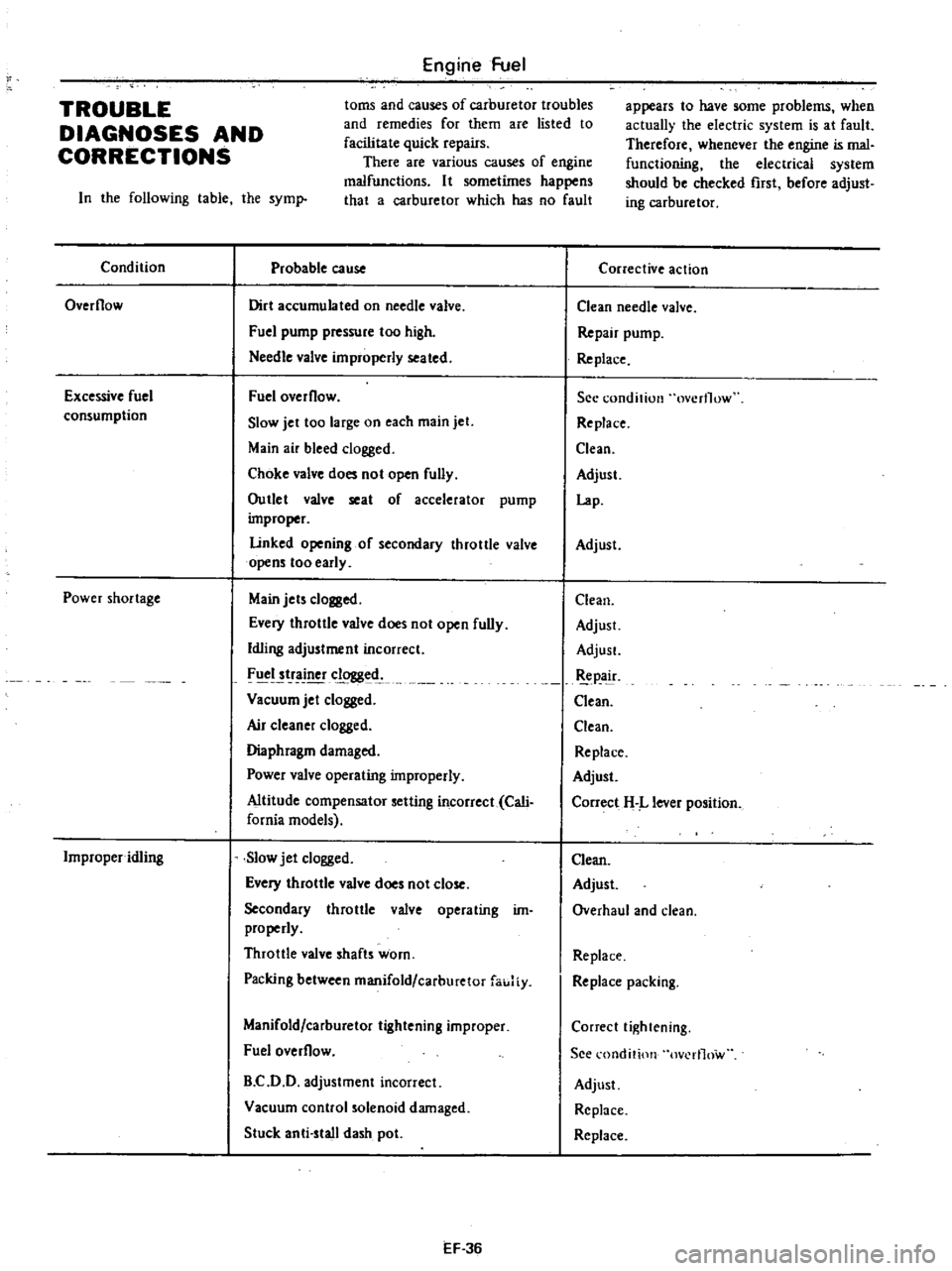
toms
and
causes
of
carburetor
troubles
and
remedies
for
them
are
listed
to
facilitate
quick
repairs
There
are
various
causes
of
engine
malfunctions
It
sometimes
happens
that
a
carburetor
which
has
no
fault
TROUBLE
DIAGNOSES
AND
CORRECTIONS
In
the
following
table
the
syml
Condition
Probable
cause
Overflow
Dirt
accumulated
on
needle
valve
Fuel
pump
pressure
too
high
Needle
valve
improperly
seated
Excessive
fuel
consumption
Fuel
overflow
Slow
jet
too
large
on
each
main
jet
Main
air
bleed
clogged
Choke
valve
does
not
open
fully
Outlet
valve
seat
of
accelerator
pump
improper
Linked
opening
of
secondary
throttle
valve
opens
too
early
Power
shortage
Main
jets
clogged
Every
throttle
valve
does
not
open
fully
Idling
adjustment
incorrect
FIICI
tr
clogged
Vacuum
jet
clogged
Air
c1eane
clogged
Diaphragm
damaged
Power
valve
operating
improperly
Altitude
compensator
setting
incorrect
Cali
fornia
models
Improper
idling
Slow
jet
clogged
Every
throttle
valve
does
not
close
Secondary
throttle
valve
operating
im
properly
Throttle
valve
shafts
worn
Packing
between
manifold
carburetor
fauJiy
Manifold
carburetor
tightening
improper
Fuel
overflow
B
C
D
D
adjustment
incorrect
Vacuum
control
solenoid
damaged
Stuck
anti
stall
dash
pot
EF
36
appears
to
have
some
problems
when
actually
the
electric
system
is
at
fault
Therefore
whenever
the
engine
is
mal
functioning
the
electrical
system
should
be
checked
rust
before
adjust
ing
carburetor
Corrective
action
Clean
needle
valve
Repair
pump
Re
place
See
condition
overflow
Replace
Clean
Adjust
Lap
Adjust
Clean
Adjust
AdjusL
pa
ir
Clean
Clean
Replace
Adjust
Correct
H
L
lever
position
Clean
Adjust
Overhaul
and
clean
Replace
Replace
packing
Correct
tightening
See
l
ondition
ov
rl1ow
Adjust
Replace
Replace
Page 133 of 537
Condition
Engine
hesitation
Engine
does
not
start
Engine
Fuel
Probable
cause
Main
jet
or
slow
jet
clogged
By
pass
hole
idle
passage
dogged
Emulsion
tube
dogged
Idling
adjustment
incorrect
Secondary
throttle
valve
operating
im
properly
Altitude
compensator
setting
incorrect
Cali
fornia
models
Fuel
overflows
No
fuel
Idling
adjustment
incorrect
Fast
idle
adjustment
incorrect
Damaged
anti
dieseling
solenoid
EF
37
Corrective
action
Clean
Clean
tube
Clean
Adjust
Overhaul
and
clean
Correct
H
L
lever
position
See
condition
overflow
Check
pump
fuel
pipe
and
needle
valve
Adjust
Adjust
Replace
Page 135 of 537

There
are
three
types
of
control
system
These
are
J
Closed
type
CIllnkcase
emission
control
system
Emission
Control
System
of
GENERAL
DESCRIPTION
2
Exhaust
emission
control
system
3
Evaporative
ell
lhsion
control
sys
tem
Pericxiic
inspection
and
required
seCV1Clng
of
these
systems
should
be
carried
out
to
reduce
harmful
emis
sions
to
a
minimum
CRANKCASE
EMISSION
CONTROL
SYSTEM
c
01
Lkf
If
1
TIL
II
tll
1
j
GUuuu
DESCRIPTION
This
system
returns
blow
by
gas
to
both
the
intake
manifold
and
carbure
tor
air
cleaner
The
positive
crankcase
ventilation
p
C
V
valve
is
provided
to
conduct
crankcase
blow
by
gas
to
the
intake
manifold
During
partial
throttle
operation
of
the
engine
the
intake
manifold
sucks
the
blow
by
gas
through
the
P
C
V
valve
Normally
the
capacity
of
the
valve
is
sufficient
to
handle
any
blow
by
and
a
small
amount
of
ventilating
air
4
c
Fresh
air
Blow
by
gas
The
ventilating
air
is
then
drawn
from
the
dust
side
of
the
cadlUretor
air
cleaner
tluough
the
tube
con
necting
carburetor
air
cleaner
to
rock
er
cover
into
the
crankcase
Under
full
tluottle
condition
the
manifold
vacuwn
is
insufficient
to
draw
the
blow
by
flow
tluough
the
valve
and
its
flow
goes
through
the
tube
connection
in
the
reverse
diree
tion
On
vehicles
with
an
excessively
high
blow
by
some
of
the
flow
will
go
through
the
tube
connection
to
carbu
retor
air
cleaner
under
all
conditions
1
Sealtypc
oil
level
gauge
2
Bame
plate
3
Flame
arrester
4
Filler
5
P
C
Y
valve
6
Steel
net
7
Bame
plate
EC716
Fig
EC
l
Crankcase
miaion
control
ay
tem
EC
2
INSPECTION
P
c
V
VALVE
AND
FILTER
Checking
P
C
V
valve
in
accord
ance
with
the
following
method
With
engine
running
at
idle
remove
the
ventilator
hose
from
P
C
V
valve
if
the
valve
is
working
a
hissing
noise
will
be
heard
as
air
passes
through
the
valve
and
a
strong
vacuwn
should
be
felt
immediately
when
a
fmger
is
placed
over
valve
inlet
Replace
P
C
V
valve
and
filter
in
accordance
with
the
maintenance
schedule
VENTILATION
HOSE
1
Check
hoses
and
hose
connec
tions
for
leaks
2
Disconnect
all
hoses
and
clean
with
compressed
air
If
any
hose
cannot
be
free
of
obstructions
replace
Ensure
that
flame
arrester
is
surely
inserted
in
hose
between
air
cleaner
and
rocker
cover
Page 140 of 537
REMOVAL
AND
INSTAUATION
Emission
Control
System
EC533
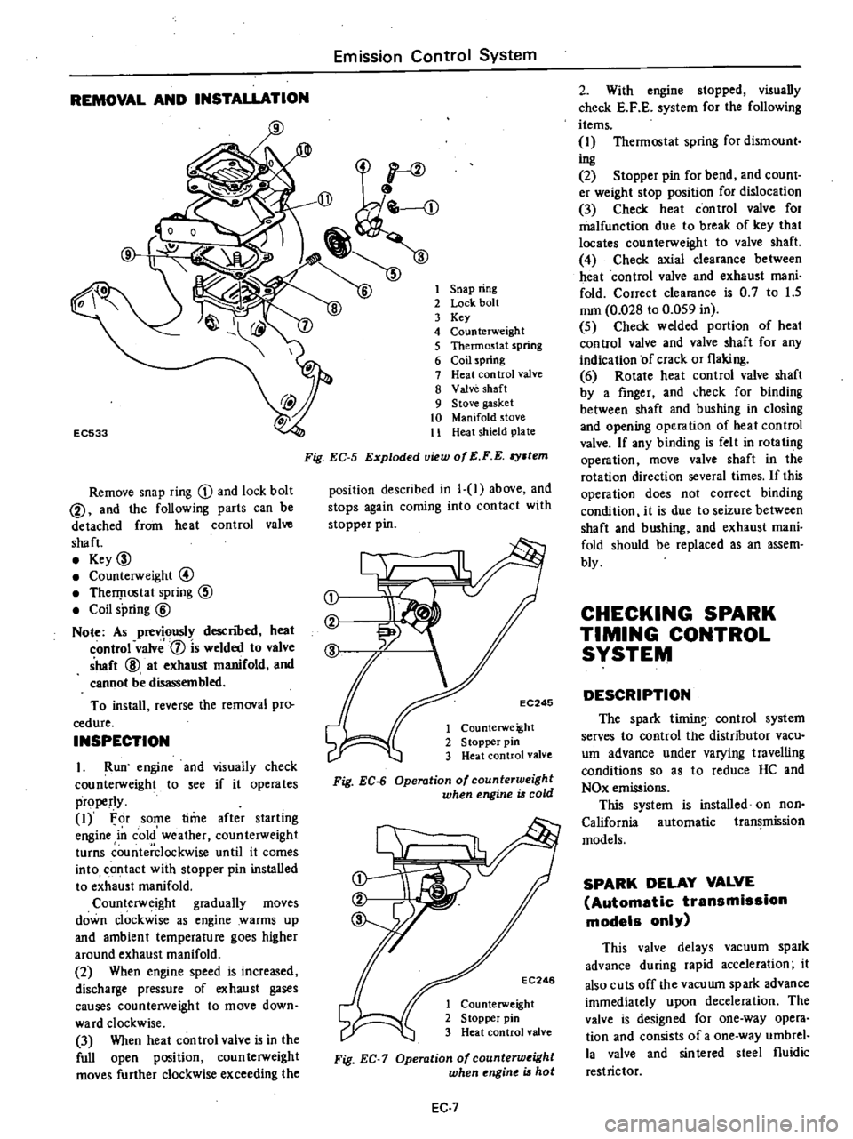
Remove
snap
ring
D
and
lock
bolt
@
and
the
following
parts
can
be
detached
from
heat
control
valve
shaft
Key
00
Counterweight
@
TherI
lostat
spring
CID
Coil
spring
@
Note
As
previously
descnoed
heat
control
valv
1
is
welded
to
valve
shaft
@
at
exhaust
manifold
and
cannot
be
disassembled
To
install
reverse
the
removal
pro
cedure
INSPECTION
I
Run
engine
and
visually
check
counterweight
to
see
if
it
operates
properly
1
For
some
time
after
starling
engine
in
cold
weather
counterweight
turns
counterclockwise
until
it
comes
into
contact
with
stopper
pin
installed
to
exhaust
manifold
Counterweight
gradually
moves
down
clockwise
as
engine
warms
up
and
ambient
temperature
goes
higher
around
exhaust
manifold
2
When
engine
speed
is
increased
discharge
pressure
of
exhaust
gases
causes
counterweight
to
move
down
ward
clockwise
3
When
heat
con
trol
valve
is
in
the
full
open
position
coun
terweight
moves
further
clockwise
exceeding
the
1
Snap
ring
2
Lock
bolt
3
Key
4
Counterweight
5
Thermostat
spring
6
Coil
spring
7
Heat
control
valve
8
Valve
shaft
9
Stove
gasket
10
Manifold
stove
11
Heat
shield
plate
Fig
EC
5
Exploded
view
of
E
F
E
stem
position
described
in
1
1
above
and
stops
again
coming
into
con
tact
with
stopper
pin
j
EC246
1
Counterweight
2
S
topper
pin
3
Heat
control
valve
Fig
EC
6
Operation
of
counterweight
when
engine
is
cold
EC246
1
Counterweight
2
Stopper
pin
3
Heat
control
valve
Fig
EC
7
Operation
of
counterw
ight
when
ngine
is
hot
EC
7
2
With
engine
stopped
visually
check
E
F
E
system
for
the
following
items
1
Thermostat
spring
for
dismount
ing
2
Stopper
pin
for
bend
and
count
er
weight
stop
position
for
dislocation
3
Check
heat
control
valve
for
malfunction
due
to
break
of
key
that
locates
counterweight
to
valve
shaft
4
Check
axial
clearance
between
heat
control
valve
and
exhaust
mani
fold
Correct
clearance
is
0
7
to
1
5
mm
0
028
to
0
059
in
5
Check
welded
portion
of
heat
control
valve
and
valve
shaft
for
any
indication
of
crack
or
flaking
6
Rotate
heat
control
valve
shaft
by
a
finger
and
check
for
binding
between
shaft
and
bushing
in
closing
and
opening
operation
of
heat
control
valve
If
any
binding
is
felt
in
rotating
operation
move
valve
shaft
in
the
rotation
direction
several
times
If
this
operation
does
not
correct
binding
condition
it
is
due
to
seizure
between
shaft
and
bushing
and
exhaust
mani
fold
should
be
replaced
as
an
assem
bly
CHECKING
SPARK
TIMING
CONTROL
SYSTEM
DESCRIPTION
The
spark
tirnin
control
system
serves
to
control
the
distributor
vacu
um
advance
under
varying
travelling
conditions
so
as
to
reduce
HC
and
NOx
emissions
This
system
is
installed
on
non
California
automatic
transmission
models
SPARK
DELAY
VALVE
Automatic
transmission
models
only
This
valve
delays
vacuum
spark
advance
during
rapid
acceleration
it
also
cuts
off
the
vacuwn
spark
advance
immediately
upon
deceleration
The
valve
is
designed
for
one
way
opera
tion
and
consists
of
a
one
way
umbrel
la
valve
and
sinlered
steel
fluidic
restrictor
Page 144 of 537
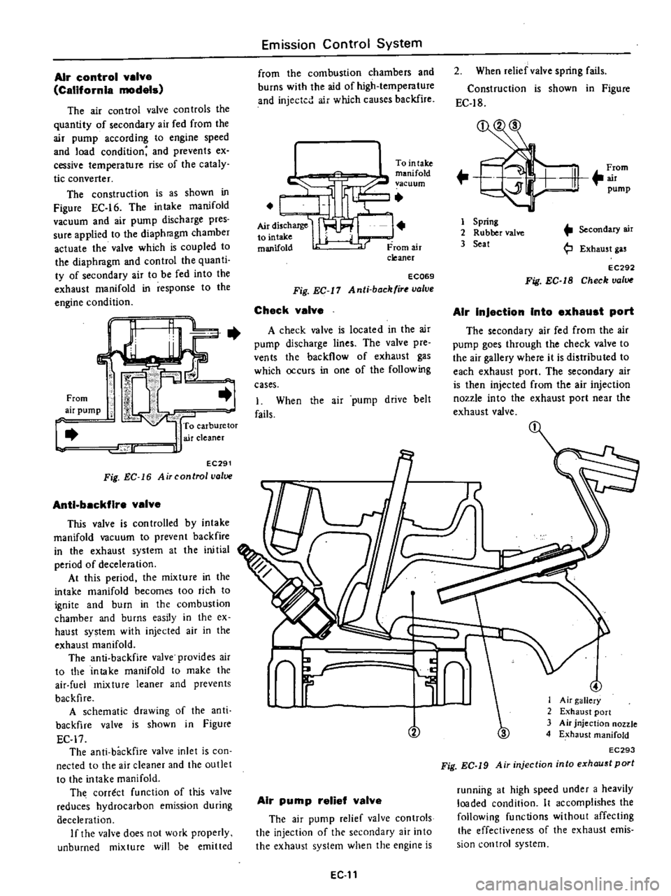
Air
control
valve
CalifornIa
models
The
air
control
valve
con
troIs
the
quantity
of
secondary
air
fed
from
the
air
pump
according
to
engine
speed
and
load
condition
and
prevents
ex
cessive
temperature
rise
of
the
cataly
tic
converter
The
construction
is
as
shown
in
Figure
EC
16
The
intake
manifold
vacuum
and
air
pump
discharge
pres
sure
applied
to
the
diaphragm
chamber
actuate
the
valve
which
is
coupled
to
the
diaphragm
and
control
the
quanti
ty
of
secondary
air
to
be
fed
into
the
exhaust
manifold
in
response
to
the
engine
condition
c
From
air
pump
To
carburetor
air
cleaner
lr
J
EC291
Fig
EC
16
Air
control
valve
Anti
backfire
valve
This
valve
is
con
trolled
by
intake
manifold
vacuum
to
prevent
backfire
in
the
exhaust
system
at
the
ini
tial
period
of
deceleration
At
this
period
the
mixture
in
the
intake
manifold
becomes
too
rich
to
ignite
and
burn
in
the
combustion
chamber
and
burns
easily
in
the
ex
haust
system
with
injected
air
in
the
exhaust
manifold
The
anti
backfire
valve
provides
air
to
the
intake
manifold
to
make
the
air
fuel
mixture
leaner
and
prevents
backfire
A
schematic
drawing
of
the
anti
backfire
valve
is
shown
in
Figure
EC
17
The
anti
backfire
valve
inlet
is
con
nected
to
the
air
cleaner
and
the
outlet
to
the
intake
manifold
Th
correct
function
of
It
jS
valve
reduces
hydrocarbon
emission
during
aeceleration
If
the
valve
does
not
work
properly
unburned
mixture
will
be
emitted
Emission
Control
System
from
the
combustion
chambers
and
burns
with
the
aid
of
high
temperature
and
injected
air
which
causes
backfire
I
Tointake
c
manifold
vacuum
I
L
AirdisChaJ1le
I
to
mtake
manifold
From
air
cleaner
ECQ69
Fig
EC
11
Anti
back
ir
valve
Check
valve
A
check
valve
is
located
in
the
air
pump
discharge
lines
The
valve
pre
ven
ts
the
backflow
of
exhaust
gas
which
occurs
in
one
of
the
following
cases
1
When
the
air
pump
drive
belt
fails
2
When
relief
valve
spring
fails
Construction
is
shown
in
Figure
EC
18
F
rom
m
pump
1
Spring
2
Rubber
valve
3
Seat
Secondary
air
Exhaust
gas
EC292
Fig
EC
1B
Check
valve
AIr
InJaction
Into
axhaust
port
The
secondary
air
fed
from
the
air
pump
goes
through
the
check
valve
to
the
air
gallery
where
it
is
distributed
to
each
exhaust
port
The
secondary
air
is
then
injected
from
the
air
injection
nozzle
into
the
exhaust
port
near
the
exhaust
valve
n
L
y
r
V
Air
pump
relief
valve
The
air
pump
relief
valve
controls
the
injection
of
the
secondary
air
into
the
exhaust
system
when
the
engine
is
EG
11
3
I
Air
gallery
2
Exhaust
port
3
Air
jnjection
nozzle
4
Exhaust
manifold
EC293
Fig
EC
19
Air
injection
into
exhaust
port
running
at
high
speed
under
a
heavily
loaded
condition
It
accomplishes
the
following
functions
without
affecting
the
effectiveness
of
the
exhaust
emis
sion
control
system
Page 145 of 537
Minimizes
exhaust
gas
tempera
lure
rise
2
Minimizes
horsepower
losses
re
suiting
from
air
injection
into
the
exhaust
system
3
Protects
pump
from
excessive
back
pressure
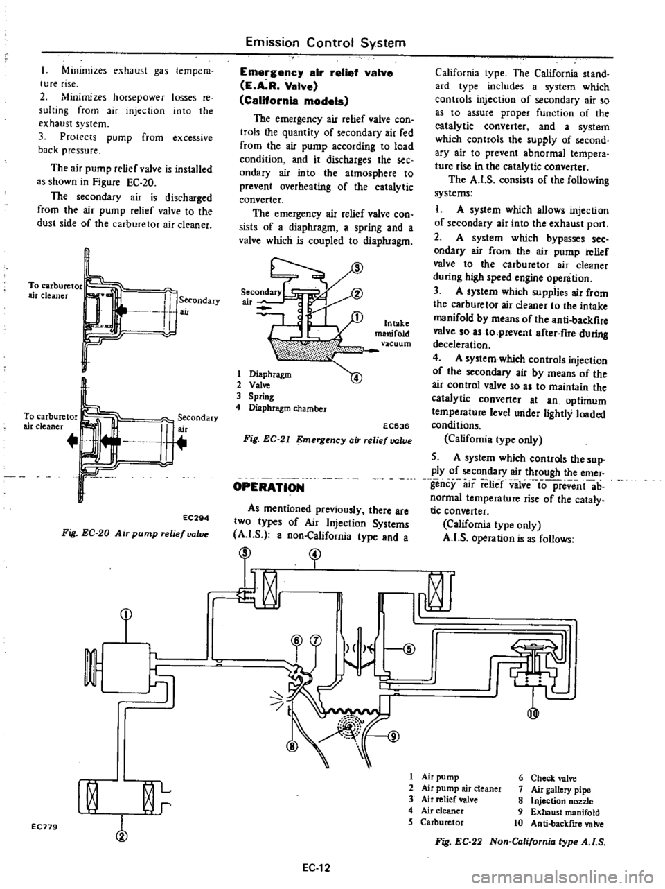
The
air
pump
relief
valve
is
installed
as
shown
in
Figure
EC
20
The
secondary
air
is
discharged
from
the
air
pump
relief
valve
to
the
dust
side
of
the
carburetor
air
cleaner
To
carburetor
air
cleaner
Secondary
air
To
carburetor
air
cleaner
J
erCOndary
r
r
EC294
Fig
EC
20
Air
pump
relief
valve
Emission
Control
System
Emargency
air
retial
valve
E
A
R
Valve
California
models
The
emergency
air
relief
valve
con
trols
the
quantity
of
secondary
air
fed
from
the
air
pump
according
to
load
condition
and
it
discharges
the
see
ondary
air
into
the
atmosphere
to
prevent
overheating
of
the
catalytic
converter
The
emergency
air
relief
valve
con
sists
of
a
diaphragm
a
spring
and
a
valve
which
is
coupled
to
diaphragm
1
Diaphragm
2
Val
3
Spring
4
Diaphragm
chamber
EC536
Fig
EC
21
mergency
air
relief
valve
OPERATION
As
mentioned
previously
there
are
two
types
of
Air
Injection
Systems
A
I
S
a
non
California
type
and
a
California
type
The
California
stand
ard
type
includes
a
system
which
controls
injection
of
secondary
air
so
as
to
assure
proper
function
of
the
catalytic
converter
and
a
system
which
controls
the
supply
of
second
ary
air
to
prevent
abnormal
tempera
tUfe
rise
in
the
catalytic
converter
The
A
I
S
consists
of
the
following
systems
L
A
system
which
allows
injection
of
secondary
air
into
the
exhaust
port
2
A
system
which
bypasses
sec
ondary
air
from
the
air
pump
relief
valve
to
the
carburetor
air
cleaner
during
high
speed
engine
operation
3
A
system
which
supplies
air
from
the
carburetor
air
cleaner
to
the
intake
manifold
by
means
of
the
anti
backfire
valve
so
as
to
prevent
after
fire
during
deceleration
4
A
system
which
controls
injection
of
the
secondary
air
by
means
of
the
air
control
valve
so
as
to
maintain
the
catalytic
converter
at
an
optimum
temperature
level
under
lightly
loaded
condi
tions
Califomia
type
only
5
A
system
which
controls
the
sup
ply
of
secondary
air
through
the
emer
gency
air
relief
vilve
io
pfevent
ab
normal
temperature
rise
of
the
cataly
tic
converter
California
type
only
A
I
S
operation
is
as
follows
I
I
t
1
r
9
I
Air
pump
6
Check
valve
I
0
L
2
Air
pump
air
deaner
7
Air
gallery
pipe
3
Air
relief
valve
8
Injection
non
e
r
4
Air
cleaner
9
Exhaust
manifold
5
Carburetor
10
Anti
backflIe
valve
EC179
Fig
EC
22
Non
California
type
A
I
S
EC
12
Page 147 of 537

9
From
air
pump
l
h
1
Not
actuated
REMOVAL
AND
INSTALLATION
Air
p
mp
sir
cleaner
Remove
air
hose
then
detach
air
cleaner
from
hoodledge
Air
cleaner
element
and
Ii
r
deancr
lower
body
are
built
into
a
unit
construction
Replace
air
cleaner
clcl
nen
and
lower
body
as
an
assembly
J
J
tt
c
t
o
J
EC
323
Fig
EC
26
Replacing
oir
cleaner
element
Air
pum
Remove
air
hoses
from
air
pump
2
Loosen
air
pump
adjusting
bar
mounting
bolts
and
air
pump
mount
ing
bolts
then
remove
air
pump
drive
bell
3
Remove
air
pump
pulley
4
Remove
air
pump
from
bracket
Air
control
valve
California
models
l
Disconnect
air
hoses
and
a
vacu
um
hose
from
air
control
valve
2
Remove
air
con
trol
valve
from
bracket
E
A
R
valve
California
modela
Remove
vacuum
pipe
and
air
hose
and
dismount
E
A
R
valve
Emission
Control
System
o
jJ
To
Intake
mamfold
rF
vacuum
r
To
air
cleaner
From
air
pump
EC781
Fig
EC
27
Locotion
of
E
A
R
wive
Antl
backflravalve
Disconnect
air
hose
and
vacuum
hose
from
anti
backfire
valve
Check
valve
Disconnect
hose
and
remove
check
valve
from
air
gallery
pipe
Air
ganery
pIpe
andinJactlon
nozzles
It
is
very
difficult
to
remove
the
air
gallery
from
the
exhaust
manifold
without
bending
the
pipe
which
could
result
in
fractures
or
leakage
There
fore
removal
of
the
air
gallery
pipe
and
injection
nozzles
should
be
under
taken
only
when
they
are
damaged
I
Lubricate
around
the
connecting
portion
of
air
injection
nozzle
and
air
gallery
with
engine
oil
2
Hold
air
injection
nozzle
hexagon
head
with
a
wrench
and
unfasten
flare
screw
connecting
ait
gallery
to
injec
tion
nozzle
Remove
air
gallery
EC
14
To
intake
manifold
vaCUl
lm
r
Y
4
9
Gf
T
I
To
air
cleaner
I
Actuated
EC299
Fig
EC
25
Operation
of
air
control
value
Notes
a
Apply
engine
011
to
rews
several
times
during
above
work
b
Be
atreful
not
to
damage
other
parts
3
Unfasten
air
injection
nozzle
from
cylinder
head
applying
engine
oil
to
screwed
portion
several
times
4
Check
air
gallery
and
nozzle
for
fractures
or
leakage
Clean
air
injection
nozzle
with
a
wire
brush
5
At
time
of
installation
hold
air
injection
nozzle
hexagon
head
with
a
wrench
and
tighten
air
gallery
flange
screw
to
a
torque
of
5
0
to
5
9
kg
m
36
to
43
ft
lb
6
Check
cylinder
head
air
injection
nozzle
and
air
gallery
for
leaks
with
engine
running
Air
pump
relief
vslve
Loosen
carburetor
air
cleaner
mounting
sc
ews
and
remove
air
pump
relief
valve
InstallatIon
Install
in
the
reverse
order
of
reo
moval
DISASSEMBLY
AND
ASSEMBLY
Disassembly
of
air
pump
1
Remove
four
pulley
drive
bolts
and
remove
pulley
from
hub
2
Secure
air
pump
drive
hub
in
a
vise
as
shewn
in
Figure
EC
28
and
remove
four
end
cover
bolts
Page 151 of 537

Air
pump
I
Operate
engine
until
it
reaches
normal
operating
temperature
2
Inspect
all
hose
hose
connec
tions
and
air
gallery
for
leaks
and
correct
if
necessary
before
checking
air
injection
pump
3
Check
air
injection
pump
belt
tension
and
adjust
to
specifications
if
necessary
4
Disconnect
air
supply
hose
at
check
valve
5
Disconnect
vacuum
hose
from
the
air
control
valve
California
type
only
6
Insert
open
pipe
end
of
Air
Pump
Test
Gauge
Adapter
STl9870000
in
air
supply
hose
Clamp
hose
securely
to
adapter
to
prevent
it
from
blowing
out
Position
adapter
and
test
lli
uge
so
that
air
blast
emitted
through
drilled
pipe
plug
will
be
harmlessly
dissipated
7
Install
a
tachometer
on
engine
With
engine
speed
at
2
600
rpm
ob
serve
pressure
produced
at
test
gauge
Air
pressure
should
be
100
mmHg
3
94
inHg
or
more
8
If
air
pressure
does
not
meet
above
specifications
proceed
as
fol
lows
I
Repeat
2
and
3
above
2
Disconnect
air
supply
hose
at
anti
backfire
valve
Plug
air
hose
open
ing
and
screw
with
a
clamp
Repeat
pressure
test
3
With
engine
speed
at
1
500
rpm
close
hole
of
test
gauge
with
finger
If
a
leaking
sound
is
heard
or
leaking
air
is
felt
by
ftnger
at
relief
valve
relief
valve
is
malfunctioning
Relief
valve
should
be
replaced
or
repaired
4
If
air
injection
pump
does
not
meet
minimum
requirement
of
pres
sure
test
it
should
be
replaced
Control
valve
The
following
procedures
are
reo
commended
for
checking
and
or
as
certaining
that
the
various
components
of
the
exhaust
emission
con
Irol
system
are
operating
properly
The
engine
and
all
components
must
be
at
normal
operating
tempera
tures
when
the
tests
are
performed
Prior
to
performing
any
extensive
diag
nosis
of
the
exhaust
control
system
it
Emission
Control
System
must
be
determined
that
the
engine
as
a
unit
is
functioning
properly
Check
valva
Warm
up
engine
thoroughly
2
Disconnect
hose
leading
to
check
valve
from
air
hose
COJUlector
3
Check
hose
opening
for
any
indi
cation
of
exhaust
gas
leaks
Ifleaks
are
detected
replace
check
valve
4
Race
the
engine
lightly
at
about
2
000
cpm
and
then
return
it
to
idling
VisuaDy
check
the
hose
for
any
indication
of
exhaust
gas
leaks
before
the
engine
returns
to
idling
speed
If
leaks
are
detected
replace
check
valve
EC310
Fig
EC
43
Checking
check
valve
Air
pump
raIle
valve
After
completing
inspection
of
air
pump
check
air
pump
relief
valve
in
the
following
steps
J
Disconnect
hoses
leading
to
check
valve
and
air
control
valve
from
air
hose
connector
and
install
blind
cap
to
the
connector
2
With
engine
running
at
about
3
000
rpm
under
no
load
place
your
hand
on
the
air
outlet
of
air
pump
relief
valve
to
check
for
discharged
air
If
no
air
is
felt
replace
the
air
pump
relief
valve
EC311
Fig
EC
44
Checking
air
pump
relief
valve
EC
18
Air
control
valve
C
U
ornla
models
I
Warm
up
engine
thoroughly
2
Before
checking
air
control
valve
check
all
hoses
for
loose
connection
leaks
etc
and
repair
or
correct
if
necessary
3
With
engine
idling
disconnect
the
outlet
side
hose
of
the
air
control
valve
and
place
your
hand
on
the
air
hose
outlet
to
check
for
air
If
no
air
is
felt
replace
the
air
control
valve
4
Pull
vacuum
hose
off
from
air
con
trol
valve
If
discharge
of
air
from
air
hose
stops
the
air
con
trol
valve
is
normaL
If
discharge
is
still
felt
replace
the
valve
Plug
up
the
removed
vacuum
hose
to
stabilize
engine
running
EC312
Fig
EC
45
Checking
air
control
valve
Emarsancy
air
rella
valve
E
A
R
Valve
lCalHornla
models
L
Warm
up
engine
thoroughly
2
Before
checking
air
control
valve
check
all
hoses
for
loose
connection
leaks
etc
and
repair
or
correct
if
necessary
3
Race
engine
approximately
2
000
rpm
under
no
load
Place
your
hand
on
air
outlet
of
E
A
R
valve
to
check
for
presence
of
discharged
air
If
no
air
is
felt
E
A
R
valve
is
normal
4
Disconnect
vacuum
hose
from
B
A
R
valve
as
shown
in
Figure
EC
46
Page 152 of 537

Race
engine
approximately
2
000
rpm
under
no
load
Place
your
hand
on
air
outlet
of
E
A
R
valve
to
check
for
presence
of
discharged
air
If
air
is
felt
E
A
R
valve
is
normaL
5
If
E
A
R
valve
does
not
function
properly
at
above
steps
replace
E
A
R
valve
To
air
pump
I
ET267
Fig
EC
46
Cheeking
E
A
R
volve
Anti
backfire
valve
A
valve
Warm
up
engine
thoroughly
2
Disconnect
hose
from
air
cleaner
and
place
a
finger
near
the
outlet
3
Run
engine
at
about
3
000
rpin
under
no
load
then
quickly
cetum
it
to
idling
If
you
feel
a
pull
or
suction
force
on
your
finger
the
anti
backfire
valve
is
functioning
normally
If
no
suction
is
felt
replace
the
anti
backflre
valve
Fig
EC
47
Checking
anti
backfire
valve
1
t
D
I
Y1
VI
I
ID
4
JO
0
2
E
C
R
control
valve
3
E
C
R
passage
4
Intake
manifold
5
Thermal
vacuum
valve
6
E
C
R
tube
7
Exhaust
manifold
Emission
Control
System
tXHAUST
GAS
RECIRCULATION
CONTROL
SYSTEM
E
G
R
DESCRIPTION
In
the
exhaust
gas
recirculation
system
a
part
of
the
exhaust
gas
is
returned
to
the
combustion
chamber
to
lower
the
spark
flame
temperature
during
combustion
This
results
in
a
reduction
of
the
nitrogen
oxide
con
ten
t
in
the
exhaust
gas
The
exhaust
gas
recirculation
sys
tem
consists
of
an
E
G
R
passage
E
G
R
con
trol
valve
thermal
vacuum
volve
E
G
R
tube
and
hose
A
warn
@
I
ing
system
which
indicates
when
the
E
G
R
control
system
must
be
in
spected
is
also
installed
in
all
620
models
except
those
bound
for
Coli
fornia
and
Canada
When
the
E
G
R
con
trol
valve
is
open
some
of
the
exhaust
gas
is
led
from
the
exhaust
manifold
to
the
E
G
R
chamber
through
the
E
G
R
passage
The
exhaust
gas
is
then
con
trolled
in
quantity
by
the
E
G
R
valve
and
is
introduced
into
the
intake
manifold
Open
c1ose
operation
of
the
E
G
R
control
valve
is
controlled
by
the
thermal
vacuum
valve
which
opera
tes
on
carburetor
vacuum
and
engine
cool
ant
temperature
EC349
Fig
EC
4
Exhaust
Gas
Recirculation
system
E
G
R
E
G
R
system
operating
Thermal
Intake
manifold
E
G
R
Remarks
E
G
R
water
temperature
oC
OF
vacuum
valve
vacuum
control
valve
Below
570C
135OF
Close
Close
Non
california
Above
MfT
models
only
Idling
Not
Above
57
to
630C
Open
70
mmHg
Close
actuated
135
to
145OF
76
inHg
California
models
Below
and
N
on
Fullthrollle
f
alifomia
AfT
Above
57
to
6
oC
models
Actua
ted
Open
Above
50
mmHg
Open
135
to
145OF
1
97
inHg
EC
19
OPERATION
Operation
of
E
G
R
system
is
as
shown
below