automatic transmission DATSUN PICK-UP 1977 User Guide
[x] Cancel search | Manufacturer: DATSUN, Model Year: 1977, Model line: PICK-UP, Model: DATSUN PICK-UP 1977Pages: 537, PDF Size: 35.48 MB
Page 29 of 537
OPERATI
NG
PRESSURE
OF
BOOST
CONTROLLED
DECELERATION
DEVICE
B
C
D
D
ADJUSTMENT
CHECKING
a
C
D
D
CIRCUIT
WITH
FUNCTION
TEST
CONNECTOR
Manual
transmission
models
I
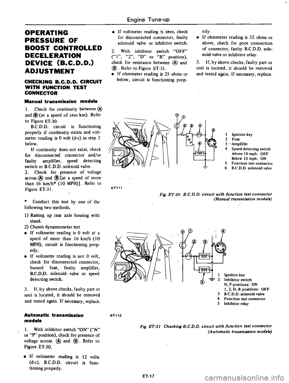
Check
for
continuity
between
@
and@
at
a
speed
of
zero
km
Refer
to
Figure
ET
30
B
C
D
D
circuit
is
functioning
properly
if
continuity
exists
and
volt
meter
reading
is
0
volt
d
c
in
step
2
below
If
continuity
does
not
exist
check
for
disconnected
connector
and
or
faulty
amplifier
speed
detecting
switch
or
B
C
D
D
solenoid
valve
2
Check
for
presence
of
voltage
across
@
and
@
at
a
speed
of
more
than
16
km
h
10
MPH
Refer
to
Figure
ET
31
Conduct
this
test
by
one
of
the
following
two
methods
i
Raising
up
rear
axle
housing
with
stand
2
Chassis
dynamometer
test
If
voltmeter
reading
is
0
volt
at
a
speed
of
more
than
16
km
h
10
MPH
circuit
is
functioning
prop
erly
If
voltmeter
reading
is
not
0
volt
check
for
disconnected
connector
burned
fuse
faulty
amplifier
B
C
D
D
solenoid
valve
or
speed
detecting
switch
3
If
by
above
checks
faulty
part
or
unit
is
located
it
should
be
removed
and
tested
again
If
necessary
replace
Automatic
transmission
models
I
With
inhibitor
switch
ON
UN
or
P
position
check
for
presence
of
voltage
across
@
and
@
Refer
to
Figure
ET
30
If
voltmeter
reading
is
12
volts
d
c
B
C
D
D
circuit
is
func
tioning
properly
Engine
Tune
up
If
voltmeter
reading
is
zero
check
for
disconnected
connector
faulty
solenoid
valve
or
inhibitor
switch
erly
If
ohmmeter
reading
is
32
ohms
or
above
check
for
poor
connection
of
connector
faulty
B
C
D
D
sole
noid
valve
or
inhibitor
relay
3
If
by
above
checks
faulty
part
or
unit
is
located
it
should
be
removed
and
tested
again
If
necessary
replace
2
With
inhibitor
switch
OFF
41
2
D
or
R
position
check
for
resistance
between
@
and
@
Refer
to
Figure
ET
31
If
ohmmeter
reading
is
25
ohms
or
below
circuit
is
functioning
prop
l
E
r
1
Ignition
key
2
Fuse
3
Amplifier
4
Speed
detecting
switch
Above
10
mph
OFF
Below
10
mph
ON
5
Function
test
connector
6
B
C
D
D
solenoid
valve
EF711
Fig
ET
30
B
C
D
D
circuit
with
function
tedconnectoT
Manual
transmission
modela
@
1
Ignition
key
2
Inhibitor
switch
N
P
positions
ON
I
2
D
R
positions
OFF
3
D
C
D
D
solenoid
valve
4
Function
test
connector
5
Inhibitor
relay
EF712
Fig
ET
31
Checking
B
C
D
D
circuit
with
function
tf
st
connf
ctor
Automatic
transmiMion
modtla
ET
17
Page 30 of 537
r
ADJUSTMENT
OF
SET
PRESSURE
OF
BOOST
CONTROLLED
DECELERATION
DEVICE
B
C
D
D
Generally
it
is
unnecessary
to
ad
just
the
B
C
D
D
however
if
it
should
become
necessary
to
adjust
it
the
procedure
is
as
follows
Prepare
the
foUowlnB
tools
I
Tachometer
to
measure
the
en
gine
speed
while
idling
and
a
screw
driver
2
A
vacuum
gauge
connecting
pipe
Note
A
qui
k
response
type
boost
gauge
such
as
Bourdon
s
type
is
recommended
a
mercury
type
manometer
should
not
be
used
To
properly
set
the
B
C
D
D
set
pressure
proceed
as
follows
I
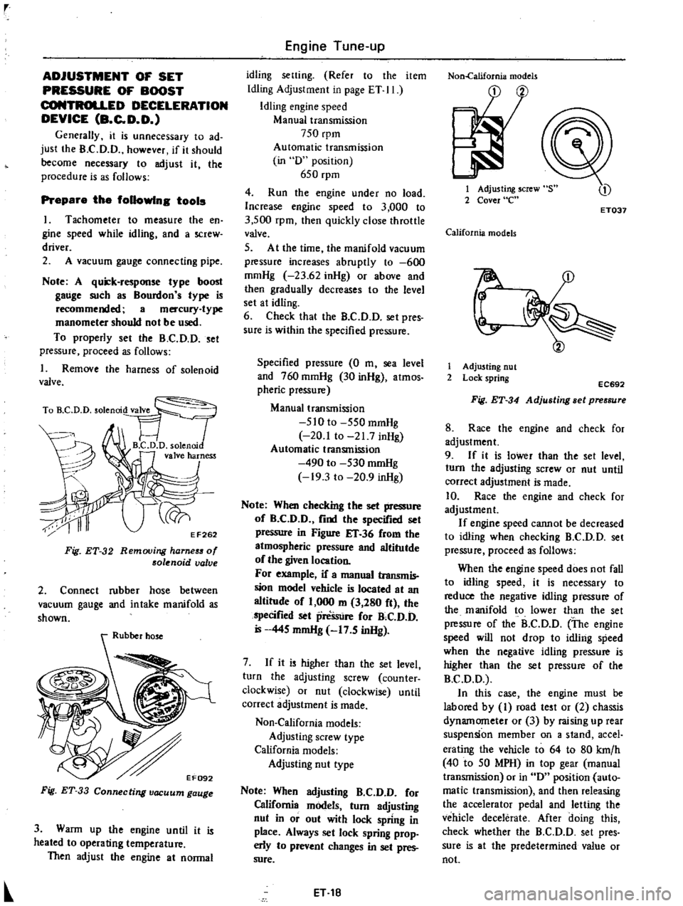
Remove
the
harness
of
solenoid
valve
TO
D
D
solenrod
VT
FJ
1
B
C
D
D
solenni
valve
harness
J
ri
y
EF262
F
g
ET
32
Removing
harneS5
of
solenoid
valve
2
Connect
rubber
hose
between
vacuum
gauge
and
intake
manifold
as
shown
Fig
ET
33
Connecting
vacuum
gauge
3
Warm
up
the
engine
until
it
is
heated
to
operating
temperature
Then
adjust
the
engine
at
normal
Engine
Tune
up
idling
setting
Refer
to
the
item
Idling
Adjustment
in
page
ET
II
Idling
engine
speed
Manual
transmission
750
rpm
Automatic
transmission
in
D
position
650
rpm
4
Run
the
engine
under
no
load
Increase
engine
speed
to
3
000
to
3
500
rpm
then
quickly
close
throttle
valve
5
At
the
time
the
manifold
vacuum
pressure
increases
abruptly
to
600
mmHg
23
62
inHg
or
above
and
then
gradually
decreases
to
the
level
set
at
idling
6
Check
that
the
B
C
D
D
set
pres
sure
is
within
the
specified
pressure
Specified
pressure
0
m
sea
level
and
760
mmHg
30
inHg
atmos
pheric
pressure
Manual
transmission
510
to
550
mmHg
20
1
to
21
7
inHg
Automatic
transmission
490
to
530
mmHg
19
3
to
20
9
inHg
Note
When
checking
the
set
pressure
of
B
C
D
D
find
the
specified
set
pressure
in
Figure
IT
36
from
the
atmospheric
pressure
and
altitutde
of
the
given
location
For
example
if
a
manual
transmis
sion
model
vehicle
is
located
at
an
altitude
of
1
000
m
3
280
ft
the
specified
set
preSsure
for
B
C
D
D
445
mmHg
17
5
inHg
7
If
it
is
higher
than
the
set
level
turn
the
adjusting
screw
counter
clockwise
or
nut
clockwise
until
correct
adjustment
is
made
Non
California
models
Adjusting
screw
type
California
models
Adjusting
nut
type
Note
When
adjusting
B
C
D
D
for
California
models
turn
adjusting
nut
in
or
out
with
lock
spring
in
place
Always
set
lock
spring
prop
erly
to
prevent
changes
in
set
pres
sure
ET
18
Non
california
models
1
Adjusting
screw
2
Cover
e
ET037
California
models
r
1
Adjusting
nut
2
Lock
spring
EC692
Fig
ET
34
Adjusting
Bet
pressure
8
Race
the
engine
and
check
for
adjustment
9
If
it
is
lower
than
the
set
level
turn
the
adjusting
screw
or
nut
until
correct
adjustment
is
made
10
Race
the
engine
and
check
for
adjustment
If
engine
speed
cannot
be
decreased
to
idling
when
checking
B
C
D
D
set
pressure
proceed
as
follows
When
the
engine
speed
does
not
fall
to
idling
speed
it
is
necessary
to
reduce
the
negative
idling
pressure
of
the
manifold
to
lower
than
the
set
pressure
of
the
B
C
D
D
The
engine
speed
will
not
drop
to
idling
speed
when
the
negative
idling
pressure
is
higher
than
the
set
pressure
of
the
B
C
D
D
In
this
case
the
engine
must
be
labored
by
I
road
test
or
2
chassis
dynamometer
or
3
by
raising
up
rear
suspension
member
on
a
stand
accel
erating
the
vehicle
to
64
to
80
krn
h
40
to
50
MPH
in
top
gear
manual
transmission
or
in
D
position
auto
matic
transmission
and
then
releasing
the
accelerator
pedal
and
letting
the
vehicle
decelerate
After
doing
this
check
whether
the
B
C
D
D
set
pres
sure
is
at
the
predetermined
value
or
not
Page 35 of 537
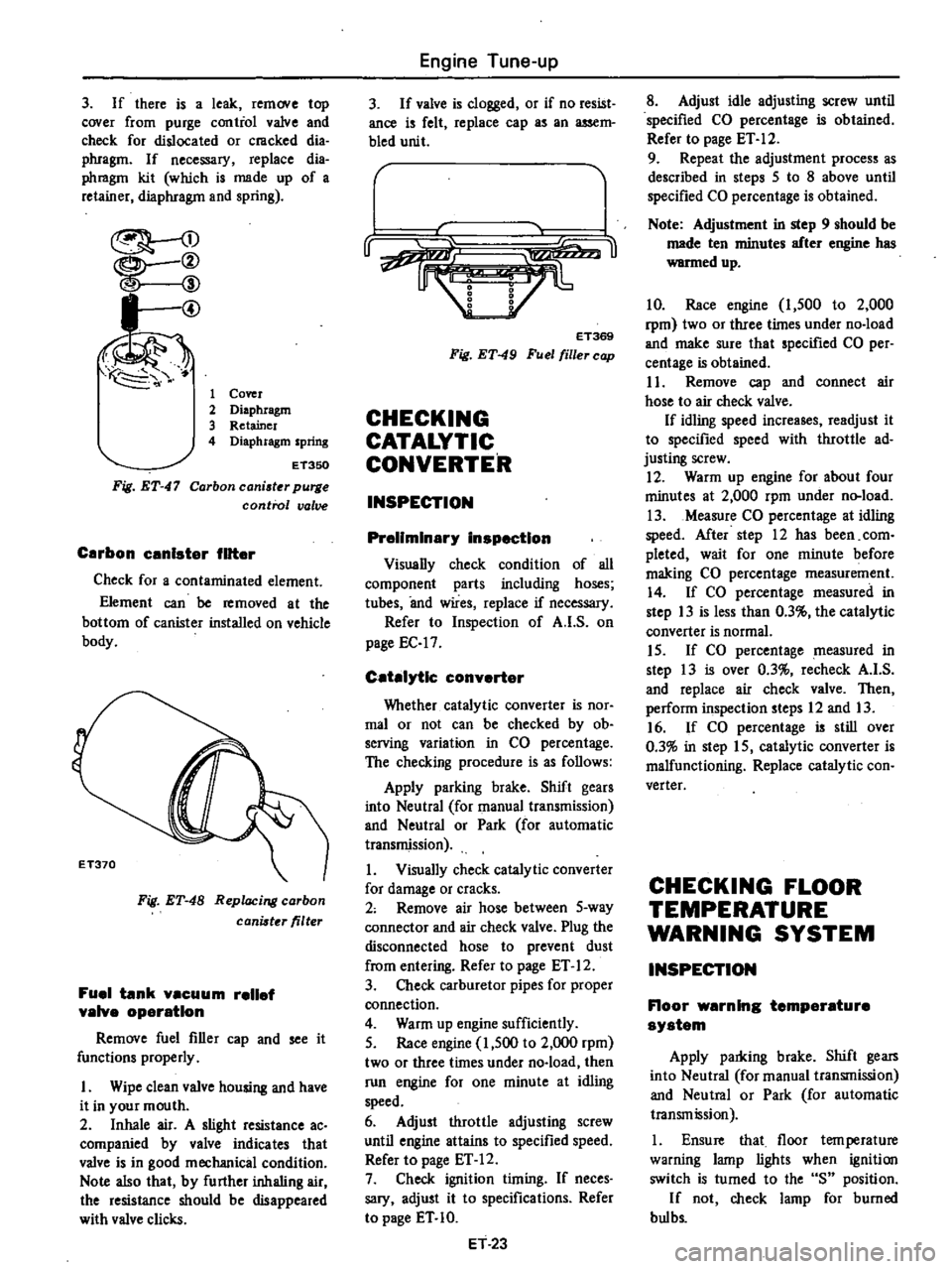
3
If
there
is
a
leak
remove
top
cover
from
purge
contiol
valve
and
check
for
dislocated
or
cmcked
dia
phragm
If
necessary
replace
dia
phmgm
kit
which
is
made
up
of
a
retainer
diaphragm
and
spring
I
@
1
Cover
2
Diaphragm
3
Retainer
4
Diaphragm
spring
Fig
ET
47
ET350
Carbon
caniater
purge
control
valve
Carbon
unlster
filter
Check
for
a
contaminated
element
Element
can
be
removed
at
the
bottom
of
canister
installed
on
vehicle
body
Fig
ET
48
Replacing
carbon
canister
filter
Fuel
tank
vacuum
relief
valve
operation
Remove
fuel
filler
cap
and
see
it
functions
properly
I
Wipe
clean
valve
housing
and
have
it
in
your
mouth
2
Inhale
air
A
slight
resistance
ac
companied
by
valve
indicates
that
valve
is
in
good
mechanical
condition
Note
also
that
by
further
inhaling
air
the
resistance
should
be
disappeared
with
valve
clicks
Engine
Tune
up
3
If
valve
is
clogged
or
if
no
resist
ance
is
felt
replace
cap
as
an
assem
bled
unit
r
u
ET369
Fig
ET
49
Fuel
filler
cap
CHECKING
CATALYTIC
CONVERTER
INSPECTION
Preliminary
inspection
Visually
check
condition
of
all
component
parts
including
hoses
tubes
and
wires
replace
if
necessary
Refer
to
Inspection
of
A
I
S
on
page
EC
17
Catalytic
converter
Whether
catalytic
converter
is
nOf
mal
or
not
can
be
checked
by
ob
serving
variation
in
CO
percentage
The
checking
procedure
is
as
follows
Apply
parking
brake
Shift
gears
into
Neutral
for
manual
transmission
and
Neutral
or
Park
for
automatic
transmission
1
Visually
check
catalytic
converter
for
damage
or
cracks
2
Remove
air
hose
between
5
way
connector
and
air
check
valve
Plug
the
disconnected
hose
to
prevent
dust
from
entering
Refer
to
page
ET
12
3
Check
carburetor
pipes
for
proper
connection
4
Warm
up
engine
sufficiently
5
Race
engine
1
500
to
2
000
rpm
two
or
three
times
under
no
load
then
run
engine
for
one
minute
at
idling
speed
6
Adjust
throttle
adjusting
screw
until
engine
attains
to
specified
speed
Refer
to
page
ET
12
7
Check
ignition
timing
If
neces
sary
adjust
it
to
specifications
Refer
to
page
ET
10
ET
23
8
Adjust
idle
adjusting
screw
until
specified
CO
percentage
is
obtained
Refer
to
page
ET
12
9
Repeat
the
adjustment
process
as
described
in
steps
5
to
8
above
until
specified
CO
percentage
is
obtained
Note
Adjustment
in
step
9
should
be
made
ten
minutes
after
engine
has
warmed
up
10
Race
engine
1
500
to
2
000
rpm
two
or
three
times
under
no
load
and
make
sure
that
specified
CO
per
centage
is
obtained
I
1
Remove
cap
and
connect
air
hose
to
air
check
valve
If
idling
speed
increases
readjust
it
to
specified
speed
with
throttle
ad
justing
screw
12
Warm
up
engine
for
about
four
minutes
at
2
000
rpm
under
n
load
13
Measure
CO
percentage
at
idling
speed
After
step
12
has
been
com
pleted
wait
for
one
minute
before
making
CO
percentage
measurement
14
If
CO
percentage
measured
in
step
13
is
less
than
0
3
the
catalylic
converter
is
normal
15
If
CO
percentage
measured
in
step
13
is
over
0
3
recheck
A
I
S
and
replace
air
check
valve
Then
perform
inspection
steps
12
and
13
16
If
CO
percentage
is
still
over
0
3
in
step
15
catalytic
converter
is
malfunctioning
Replace
catalytic
con
verter
CHECKING
FLOOR
TEMPERATURE
WARNING
SYSTEM
INSPECTION
Floor
warning
temperature
system
Apply
parldng
brake
Shift
gears
into
Neutral
for
manual
transmission
and
Neutral
or
Park
for
automatic
transmission
1
Ensure
that
floor
tern
perature
warning
lamp
lights
when
ignition
switch
is
turned
to
the
S
position
If
not
check
lamp
for
burned
bul
bs
Page 37 of 537
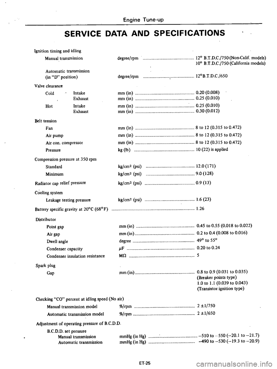
Engine
Tune
up
SERVICE
DATA
AND
SPECIFICATIONS
Ignition
timing
and
idling
Manual
transmission
Automatic
transmission
in
D
position
Valve
clearance
Cold
Intake
Exhaust
Intake
Exhaust
Hot
Belt
tension
Fan
Air
pump
Air
coo
compressor
Pressure
Compression
pressure
at
350
rpm
Standard
Minimum
Radiator
cap
relief
pressure
Cooling
system
Leakage
testing
pressure
Battery
specific
gravity
at
200C
680F
Distribu
tor
Point
gap
Air
gap
Dwell
angle
Condenser
capacity
Condenser
insulation
resistance
Spark
plug
Gap
degree
rpm
120
B
T
D
C
j750
Non
Calif
models
100
B
T
D
C
j750
California
models
degree
rpm
l20B
T
D
C
j650
mm
in
mm
in
mm
in
mm
in
0
20
0
008
0
25
0
010
0
25
0
010
0
30
0
012
mm
in
mm
in
mm
in
kg
lb
8
to
12
0
315
to
0
472
8to
12
0
315
to
0
472
8
to
12
0
315
to
0
472
10
22
is
applied
kg
cm2
psi
kg
em2
psi
kg
em
2
psi
12
0
171
9
0
128
0
9
13
kg
cm2
Psi
1
6
23
1
26
mm
in
mm
in
degree
IF
Mil
0
45
to
0
55
0
018
to
0
022
0
2
to
0
4
0
008
to
0
016
490
to
550
0
20
to
0
24
5
mm
in
0
8
to
0
9
0
031
to
0
035
Breaker
points
type
1
0
to
1
1
0
039
to
0
043
Transistor
ignition
type
Checking
CO
percent
at
idling
speed
No
air
Manual
transmission
model
rpm
Automatic
transmission
model
rpm
Adjustment
of
operating
pressure
of
B
C
D
D
B
C
D
D
set
pressure
Manual
transmission
Automatic
transmission
2
1
1
750
2
1
1
650
mmHg
in
Hg
mmHg
in
Hg
510
to
550
20
1
to
21
7
490
to
530
19
3
to
20
9
ET
25
Page 47 of 537
Engine
Mechanical
GENERAL
DESCRIPTION
MODEL
L20B
ENGINE
CYLINDER
BLOCK
CRANKSHAFT
PISTON
AND
CONNECTING
ROD
CYLINDER
HEAD
CONTENTS
EM
2
EM
3
EM
3
EM
3
EM
3
CAMSHAFT
VALVE
MECHANISM
CAMSHAFT
DRIVE
MANIFOLDS
out
smooth
dependable
power
The
cylinder
block
is
cast
as
a
single
unit
and
featllres
deep
skirting
This
engine
is
equipped
with
a
single
2
barrel
downdraft
carburetor
that
in
corporates
a
special
device
to
control
emissions
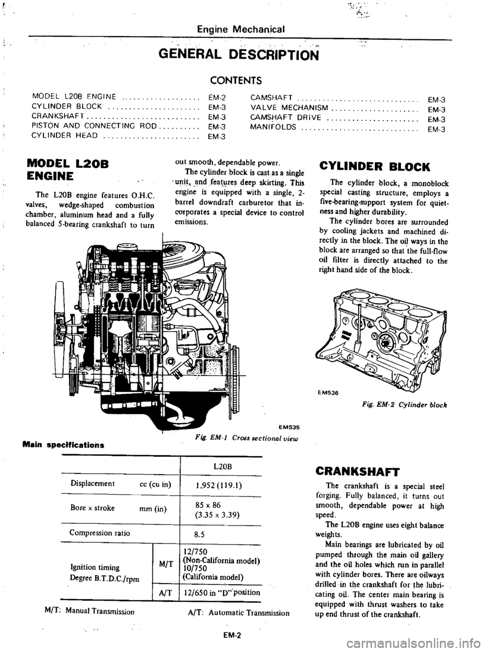
MODEL
L20B
ENGINE
The
L20B
engine
features
O
H
C
valves
wedge
shaped
combustion
chamber
aluminum
head
and
a
fully
balanced
5
bearing
crankshaft
to
turn
Main
specifications
Oisplacemen
t
cc
cu
in
Bore
x
stroke
mm
in
Compression
ratio
Ignition
timing
Degree
B
T
O
C
rpm
MIT
AlT
MIT
Manual
Transmission
EM535
Fig
EM
Cross
sectional
view
L20B
1
952
1191
85
X
86
3
35
x
3
39
8
5
12
750
Non
California
model
10
750
California
model
12
650
in
0
position
AIT
Automatic
Transmission
EM
2
EM
3
EM
3
EM
3
EM
3
CYLINDER
BLOCK
The
cylinder
block
a
mono
block
special
casting
structure
employs
a
five
bearing
support
system
for
quiet
ness
and
higher
durability
The
cylinder
bores
are
surrounded
by
cooling
jackets
and
machined
di
rectly
in
the
block
The
oil
ways
in
the
block
are
arranged
so
that
the
full
flow
oil
filter
is
directly
attached
to
the
right
hand
side
of
the
block
EM536
Fig
EM
2
Cylinder
block
CRANKSHAFT
The
crankshaft
is
a
special
steel
forging
Fully
balanced
it
turns
out
smooth
dependable
power
at
high
speed
The
L20B
engine
uses
eight
balance
weights
Main
bearings
are
lubricated
by
oil
pumped
through
the
main
oil
gallery
and
the
oil
holes
which
run
in
parallel
with
cylinder
bores
There
are
oilways
drilled
in
the
crankshaft
for
the
lubri
cating
oil
The
center
main
bearing
is
equipped
with
thrust
washers
to
take
up
end
thrust
of
the
crankshaft
Page 49 of 537
r
I
I
PRELIMINARY
CLEANING
AND
INSPECTION
DISASSEMBL
Y
PRELIMINARY
CLEANING
AND
INSt
ECTION
Before
disassembling
engine
note
the
following
I
Fuel
oil
or
water
may
leak
past
cylinder
head
and
block
Prior
to
disassembling
check
cylinder
head
1
1ltermal
vacuum
valve
2
Check
valve
3
Altitude
compensator
in
air
cleaner
4
Air
gallery
pipe
S
Auto
choke
6
Automatic
temperature
control
air
cleaner
7
Anti
8ackfire
valve
A
B
valve
8
Boost
Controlled
Deceleration
Device
Bee
D
D
9
P
c
v
valve
to
Air
relief
valve
11
E
G
R
control
valve
12
B
C
D
D
control
valve
and
solenoid
valve
13
Emergency
air
relief
valve
14
Air
pump
air
cleaner
IS
Carbon
canister
16
Air
control
valve
11
Air
pump
Engine
Mechanical
ENGINE
DISASSEMBLY
CONTENTS
EM
4
EM
4
PISTONS
AND
CONNECTING
RODS
CYLINDER
HE
AD
EM
7
EM
7
front
chain
cover
oil
pan
and
oil
filter
gaskets
lInd
crankshaft
and
water
pump
seals
for
signs
of
leakage
past
their
gasketed
surfaces
2
Check
carburetor
and
fuel
pump
for
condition
fuel
hoses
for
deteriora
tion
cracks
or
leakage
of
fuel
past
their
jointed
or
connected
surfaces
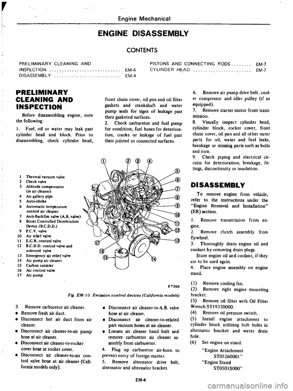
Fig
EM
0
Emiuion
control
devic
s
California
mod
18
E
T366
3
Remove
carburetor
air
cleaner
Remove
fresh
air
duct
Disconnect
hot
air
duct
from
air
cleaner
Disconnect
air
cleaner
to
air
pump
hose
at
air
cleaner
Disconnect
air
cleanef
to
rocker
cover
hose
at
rocker
cover
Disconnect
air
cIeaner
to
air
con
trol
valve
hose
at
air
cleaner
Cali
fornia
models
only
Disconnect
air
cleaner
to
A
B
valve
hose
at
air
cleaner
Disconnect
air
cleaner
to
related
part
vacuum
hoses
at
air
cleaner
Loosen
air
cleaner
band
bolt
and
remove
carburetor
air
cleaner
as
sembly
from
carburetor
4
Plug
up
carburetor
air
horn
to
prevent
entry
of
foreign
matter
5
Remove
alternator
drive
belt
alternator
and
alternator
bracket
EM
4
6
Remove
air
pump
drive
belt
cool
er
compressor
and
idler
pulley
if
so
equipped
7
Remove
starter
motor
from
trans
mission
8
Visually
inspect
cylinder
head
cylinder
block
rocker
C
Ner
front
chain
cover
oil
pan
and
all
other
outer
parts
for
oil
water
and
fuel
leaks
breakage
or
missing
parts
such
as
bolts
and
nuts
9
Check
piping
and
electrical
cir
cuits
for
deterioration
breakage
fit
tings
discontinuity
or
insulation
DISASSEMBLY
To
remove
engine
from
vehicle
refer
to
the
instructions
under
the
Engine
Removal
and
Installation
ER
section
I
Remove
transmission
from
en
gine
2
Remove
clutch
assembly
from
flywheeL
3
Thoroughly
drain
engine
oil
and
coolan
t
by
removing
drain
plugs
Store
engine
oil
and
coolant
if
they
are
to
be
used
again
4
Place
engine
assembly
on
engine
stand
I
Remove
cooling
fan
2
Remove
right
engine
mounting
bracket
3
Remove
oil
filter
with
Oil
Filter
Wrench
STI9320000
4
Remove
oil
pressure
swi
tch
5
Install
engine
attachment
to
cylinder
block
utilizing
bolt
holes
in
alternator
bracket
and
water
drain
hole
6
Set
engine
on
stand
Engine
Attachment
ST05260001
Engine
Stand
ST050I
SOOO
Page 72 of 537
Engine
Mechanical
SERVICE
DATA
AND
SPECIFICATIONS
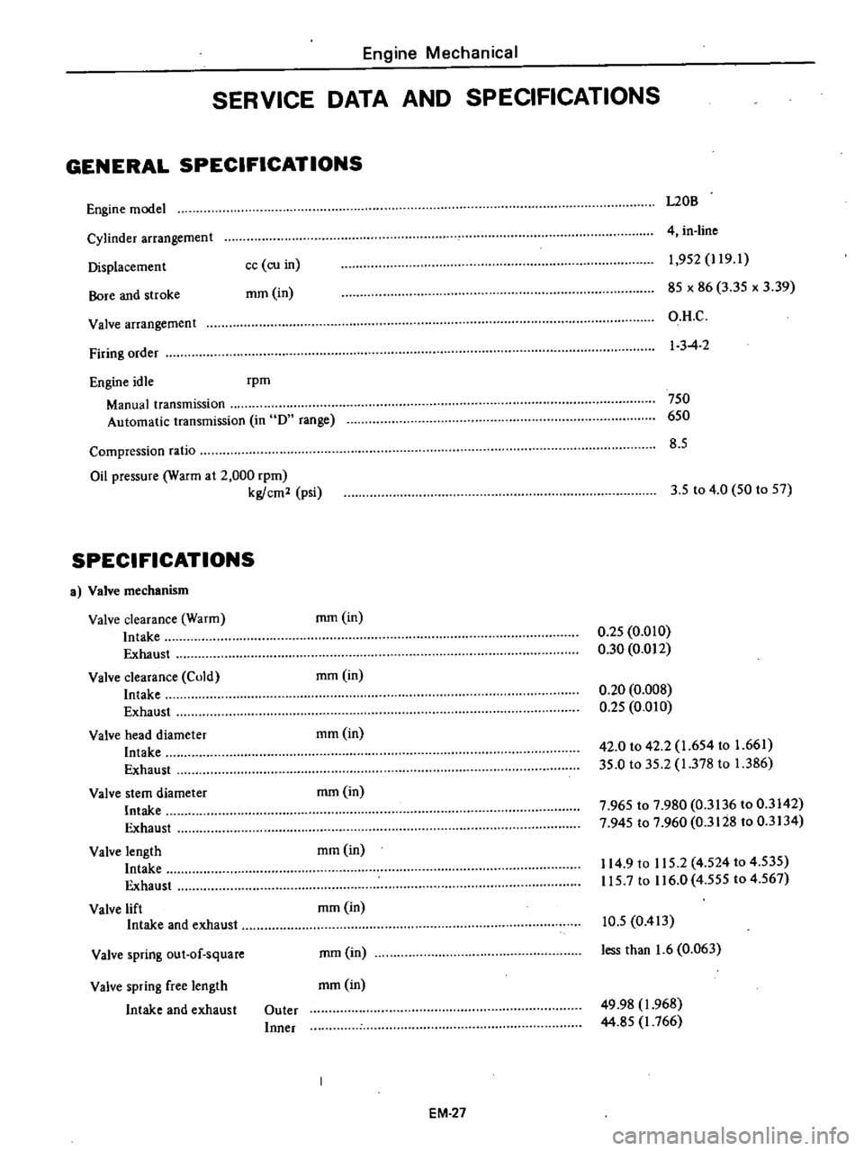
GENERAL
SPECIFICATIONS
Engine
model
L20B
Cylinder
arrangement
Displacemen
t
Bore
and
stroke
4
in
line
cc
co
in
mm
in
1
952
J
19
1
85
x
86
3
35
x
3
39
O
H
C
I
3
4
2
Valve
arrangement
Firing
order
Engine
idle
rpm
Manual
transmission
Automatic
transmission
in
D
range
750
650
8
5
Compression
ratio
Oil
pressure
Warm
at
2
000
rpm
kg
cm2
psi
3
5
to
4
0
50
to
57
SPECIFICATIONS
a
Valve
mechanism
Valve
clearance
Warm
Intake
Exhaust
Valve
clearance
Cold
Intake
Exhaust
Valve
head
diameter
Intake
Exhaust
Valve
stem
diameter
Intake
Exhaust
Valve
length
Intake
Exhaust
Valve
lift
Intake
and
exhaust
mm
in
0
25
0
010
0
30
0
012
mmOn
0
20
0
008
0
25
0
010
mm
in
42
0
to
42
2
1
654
to
1
661
35
0
to
35
2
1
378
to
1
386
mm
in
7
965
to
7
980
0
3136
to
0
3142
7
945
to
7
960
0
3128
to
0
3134
mmOn
114
9
to
115
2
4
524
to
4
535
115
7
to
116
0
4
555
to
4
567
mmOn
Valve
spring
out
of
square
mm
in
10
5
0
413
less
than
1
6
0
063
Valve
spring
free
length
mm
in
Intake
and
exhaust
Outer
Inner
49
98
1
968
44
85
J
766
EM
27
Page 95 of 537
r
direction
when
hoses
are
assembled
3
Ensure
that
clearance
between
radiator
hose
and
any
adjacent
parts
is
30
mm
I
181
in
minimum
On
mod
els
equipped
with
air
conditions
a
minimum
clearance
of
18
mm
0
709
in
should
exist
between
compressor
and
hose
4
Ensure
that
clearance
between
shroud
and
fan
is
even
at
any
place
Note
Be
careful
not
to
damage
radia
tor
fins
and
core
tube
when
in
stalling
INSPECTION
Radiator
cap
should
be
checked
for
working
pressure
at
regular
tune
up
intervals
First
check
rubber
seal
on
cap
for
tears
cracks
or
deterioration
Cooling
System
after
cleaning
it
Then
install
radiator
cap
on
a
tester
If
cap
does
not
hold
or
will
not
release
at
the
specified
pres
sure
replace
cap
Fig
CO
9
Telting
radiator
cap
Also
inspect
radiator
for
leakage
using
cap
tester
and
applying
a
pres
sure
of
1
6
kg
cm
22
8
psi
If
a
leakage
is
detected
repair
or
replace
radiator
Fig
CO
IO
Testing
cooling
6ystem
pUS
ure
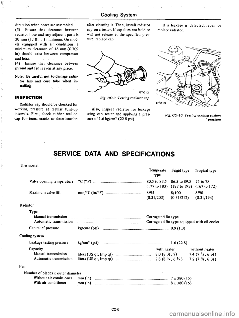
SERVICE
DATA
AND
SPECIFICATIONS
Thermostat
Valve
opening
temperature
oC
F
Maximum
valve
lift
mm
oC
inj
F
Radia
tor
Type
Manual
transmission
Automatic
transmission
Cap
relief
pressure
Cooling
system
Leakage
testing
pressure
Capacity
Manual
transmission
Automatic
transmission
Fan
Number
of
blades
x
outer
diameter
Without
air
conditioner
mm
in
With
air
conditioner
mm
in
kg
em
psi
kg
em
psi
liters
US
qt
Imp
qt
liters
US
qt
Imp
qt
CO
6
Temperate
Frigid
type
Tropical
type
type
80
5
to
83
5
86
5
to
89
5
75
to
78
177
to
183
187
to
193
167
to
172
8
95
8
100
8
90
0
31
203
0
31
212
0
31
194
Corrugated
fin
type
Corrugated
fin
type
equipped
with
oil
cooler
0
9
1
3
1
6
22
8
with
heater
8
0
8
Ii
7
7
8
8
Y
6
J
i
without
heater
74
7J
i6
1i
7
2
7
X
6
X
7
x
380
15
8
x
380
15
Page 114 of 537
FLOAT
SYSTEM
There
IS
only
one
float
chamber
while
two
l
arburetor
systems
primary
Jnd
st
l
ondary
are
provided
Fuel
fed
from
the
fuel
pump
flows
through
the
filler
and
needle
valve
into
the
flo
t
chamber
A
constant
fuel
level
is
maintained
by
the
float
and
needle
valve
Because
of
the
inner
air
vent
type
of
the
float
chamber
ventilation
the
fuel
consumption
will
not
be
in
fluenced
by
some
dirt
accumulated
in
the
air
deaner
The
needle
valve
includes
special
hard
steel
ball
and
will
not
wear
for
all
its
considerably
long
use
Besides
the
inserrion
of
a
spring
wiU
prevent
the
flooding
at
rough
road
running
BOOST
CONTROLLED
DECELERATION
DEVICE
B
C
D
D
A
Boost
Controlled
Deceleration
Device
B
C
D
D
serves
to
reduce
the
hydrocarbons
He
emitted
from
en
gine
during
coasting
The
high
manifold
vacuum
during
coasting
prevents
the
mixture
from
complete
combustion
because
of
the
reduced
amount
of
mixture
per
cyl
inder
per
rotation
of
engine
with
the
result
that
a
large
amount
of
hydrocar
bons
is
emitted
into
tile
atmosphere
The
B
C
D
D
has
been
designed
to
correct
this
problem
It
opern
tes
as
follows
when
the
manifold
vacuum
exceeds
a
pre
Engine
Fuel
determined
value
the
B
C
D
D
intro
duces
an
additional
mixture
of
opti
mum
mixture
ratio
and
quantity
into
the
manifold
by
opening
a
separate
mixture
passage
in
the
carburetor
Complete
combustion
of
fuel
is
assist
ed
by
this
additional
mixture
and
the
amount
of
H
C
contained
in
exhaust
gases
is
dramatically
reduced
During
the
transition
period
from
coasting
to
idling
the
transmission
produces
a
signal
which
turns
on
the
vacuum
control
solenoid
valve
As
this
takes
place
the
valve
is
lifted
off
its
seat
opening
the
vacuum
chamber
to
the
atmosphere
The
mixture
control
valve
is
then
closed
returning
the
engine
to
the
predetermined
idling
speed
On
manual
transmission
models
this
system
consists
of
B
C
D
D
vacuo
urn
control
solenoid
valve
speed
de
tecting
switch
and
amplifier
On
automatic
transmission
models
it
consists
of
B
C
D
D
vacuum
con
trol
solenoid
valve
and
inhibitor
switch
B
C
D
D
operation
Diaphragm
I
Qj
monitors
the
mani
fold
vacuum
and
when
the
vacuum
exceeds
a
pre
fetermined
value
acts
so
as
to
open
the
vacuum
control
valve
@
This
causes
the
manifold
vacu
urn
to
be
introduced
into
the
second
vacuum
chamber
and
actuates
dia
phragm
ll@
When
diaphrngm
II
operates
the
mixture
control
valve
@
opens
the
passage
and
introduces
the
additional
mixture
into
the
manifold
EF
18
The
amount
of
the
mixture
is
con
trolled
by
the
servo
action
of
the
mixture
control
valve
CID
and
vacuum
control
valve
@
so
that
the
manifold
vacuum
may
be
kept
at
the
pre
determined
value
The
amount
of
mixture
depends
mainly
upon
the
coasting
air
bleed
II@
while
the
mixture
ratio
is
deter
mined
by
the
coasting
jet
@
and
coasting
air
bleed
@
See
Figure
EF
31
Vacuum
control
solenoid
valve
operation
Manual
transmission
models
The
vacuum
control
solenoid
valve
is
con
troDed
by
a
speed
detecting
switch
that
is
actuated
by
the
speed
ometer
needle
As
the
vehicle
speed
falls
below
10
MPH
this
switch
is
activated
pro
ducing
a
signal
This
signal
actuates
the
amplifier
to
open
the
vacuum
control
solenoid
valve
Automatic
transmission
models
When
the
shift
lever
is
in
N
or
P
position
the
inhibitor
switch
mounted
on
the
transmission
turns
on
to
open
the
vacuum
control
solenoid
valve
Page 115 of 537

I
Air
jet
2
Diaphragm
II
3
Mixture
control
valve
4
Coasting
air
bleed
II
5
Mixture
air
passage
6
Secondary
baHel
7
Intake
manifold
8
Boost
passage
9
Vacuum
control
solenoid
valve
10
Vacuum
control
valve
II
Diaphragm
I
Engine
Fuel
12
Secondary
main
jet
13
Coasting
jet
14
Coasting
air
bleed
I
15
Inhibitor
switch
N
P
ON
for
automatic
transmission
16
Amplifier
1
7
Speed
de
tecting
swi
tch
below
10
M
P
H
ON
for
manual
transmission
1
W
j
I
t
i
J
l
J
18
Ignition
switch
CID
1
1
fI3
6
@
I
r
101
@
i
r
@
JJ
Note
Broken
line
applies
only
to
Automatic
Transmission
I
Ignition
switch
2
Amplifier
3
Speed
detecting
switch
below
10
M
P
H
ON
for
manual
transmission
4
Inhibitor
switch
N
p
ON
for
automatic
transmission
5
Solenoid
valve
6
Vacuum
control
valve
7
Altitude
corrector
LlJ
I
I
l
f
L8
J
l
EF231
Fig
EF
31
Schematic
drawing
of
B
C
D
D
Non
California
models
1
J
ru
I
r
lJ
i7
I
To
intake
manifold
To
air
cleaner
E
F235
Note
Broken
line
applies
only
to
Automatic
Transmission
Fig
EF
32
Schematic
drawing
of
RC
D
D
California
models
EF
19