weight DATSUN PICK-UP 1977 User Guide
[x] Cancel search | Manufacturer: DATSUN, Model Year: 1977, Model line: PICK-UP, Model: DATSUN PICK-UP 1977Pages: 537, PDF Size: 35.48 MB
Page 198 of 537
CHECKING
AND
ADJUSTMENT
CAP
AND
ROTOR
HEAD
Cap
and
rotor
head
should
be
in
spected
periodically
as
specified
in
the
Maintenance
Schedule
Remove
cap
and
clean
all
dust
and
carbon
deposits
from
cap
and
rotor
If
cap
is
cracked
or
is
leaking
replace
with
a
De
one
CONTACT
POINT
Contact
point
should
be
replaced
in
accordance
with
the
Maintenance
Schedule
Standard
point
gap
is
0
45
to
0
55
mm
O
OIS
to
0
022
in
In
case
size
is
off
the
standard
adjustment
is
made
by
loosening
point
screws
Gap
gauge
is
required
for
adjustment
When
point
surface
is
rough
take
off
any
irregularities
with
fine
sand
paper
of
No
500
or
600
or
with
oil
stone
When
wear
on
contact
points
is
noticeable
replace
points
together
with
contact
arm
To
replace
proceed
as
follows
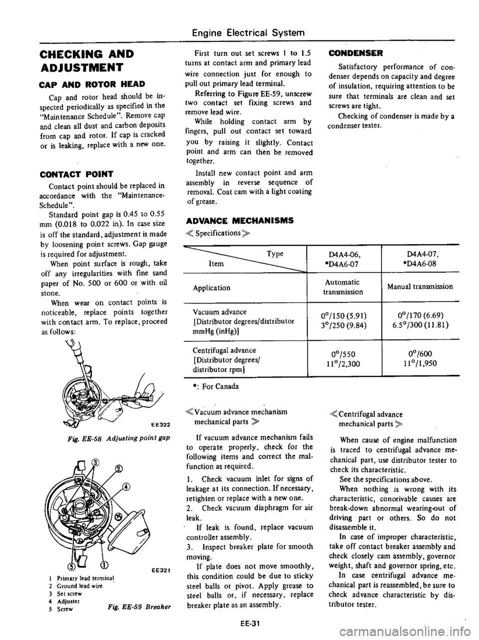
EE322
Fig
EE
58
Adju
ting
point
gap
EE321
I
Primary
lead
termina
2
Ground
lead
wire
3
Set
screw
4
Adjuster
5
Screw
Fig
EE
59
Breaker
Engine
Electrical
System
First
turn
out
set
screws
1
to
1
5
turns
at
contact
arm
and
primary
lead
wire
connection
just
for
enough
to
pull
out
primary
lead
terminal
Referring
to
Figure
EE
59
unSCrew
two
contact
set
fixing
screws
and
remove
lead
wire
While
holding
contact
arm
by
fingers
pull
out
contact
set
toward
you
by
raising
it
slightly
Contact
point
and
afm
can
then
be
removed
together
Install
new
contact
point
and
arm
assembly
in
reverse
sequence
of
removal
Coat
cam
with
a
light
coating
of
grease
ADVANCE
MECHANISMS
Specifications
Application
Vacuum
advance
Distributor
degrees
distributor
mmHg
inHg
Centrifugal
advance
Distributor
degrees
distribu
tor
rpm
For
Canada
Vacuum
advance
mechanism
mechanical
parts
If
vacuum
advance
mechanism
fails
to
operate
properly
check
for
the
following
items
and
correct
the
mal
function
as
required
1
Check
vacuum
inlet
for
signs
of
leakage
at
its
connection
Ifnecessacy
retighten
or
replace
with
a
new
one
2
Check
vacuum
diaphragm
for
air
leak
If
leak
is
found
replace
vacuum
controller
assembly
3
Inspect
breaker
plate
for
smooth
moving
If
pia
te
does
not
move
smoothly
this
condition
could
be
due
to
sticky
steel
balls
or
pivot
Apply
grease
to
steel
balls
or
if
necessary
replace
breaker
plate
as
an
assembly
EE
31
CONDENSER
Satisfactory
performance
of
con
denser
depends
on
capacity
and
degree
of
insulation
requiring
attention
to
be
sure
that
terminals
are
clean
and
set
screws
are
tight
Checking
of
condenser
is
made
by
a
condenser
tester
D4A4
06
D4A6
07
D4A4
07
D4A6
0S
Automatic
transmission
Manual
transmission
00
150
5
91
30
250
9
S4
00
170
6
69
6
50
300
1I
S1
00
550
11
0
2
300
00
600
110
1
950
Centrifugal
advance
mechanical
parts
When
cause
of
engine
malfunction
is
traced
to
centrifugal
advance
me
chanical
part
use
distributor
tester
to
check
its
characteristic
See
the
specifications
above
When
nothing
is
wrong
with
its
characteristic
conceivable
causes
are
break
down
abnormal
wearing
out
of
driving
part
or
others
So
do
not
disassemble
it
In
case
of
improper
characteristic
take
off
contact
breaker
assembly
and
check
closely
cam
assembly
governor
weight
shaft
and
governor
spring
etc
In
case
centrifugal
advance
me
chanical
part
is
reassembled
be
sure
to
check
advance
characteristic
by
dis
tributor
tester
Page 199 of 537

DISASSEMBLY
To
disassemble
follow
the
below
proccd
ure
I
Take
off
cap
and
disconnect
rotor
head
2
Remove
vacuum
controller
EE291
Fig
EE
60
Removing
vacuum
controller
3
Remove
contact
set
Refer
to
Page
EE
31
when
contact
set
i
removed
EE323
Fig
EE
61
Removing
contact
tel
EE324
Fig
EE
62
Removing
breaker
plate
Engine
Electrical
System
4
When
breaker
plate
is
removed
be
careful
not
to
lose
steel
balls
between
breaker
spring
and
breaker
plate
5
Pul
roll
pin
out
and
siconnect
collar
to
remove
the
entire
rotating
parts
EE325
Fig
EE
63
Removing
roll
pin
EE326
Fig
EE
64
Removil1l
rotation
paTta
6
Remove
packing
from
the
top
of
cam
assembly
and
unscrew
earn
astern
bly
setscrew
Put
match
mark
across
earn
and
shaft
so
that
original
combi
nation
can
be
restored
at
assembly
EE
32
EE075
Fig
EE
65
Removing
cam
7
When
governor
weight
and
spring
are
disconnected
be
careful
not
to
stretch
or
deform
governor
spring
After
disassembling
apply
grease
to
governor
weights
ASSEMBLY
To
assemble
reverse
the
order
of
disassembly
Carefully
observe
the
fol
lowing
instructions
Align
match
marl
s
so
that
parts
are
assembled
to
their
original
posi
tions
2
Apply
grease
to
the
top
of
cam
assembly
as
required
3
Check
the
operation
of
governor
before
installing
distributor
on
engine
4
Adjust
ignition
timing
afteT
dis
tributor
is
installed
on
engine
Page 202 of 537
Vacuum
advance
mechanism
mechanical
parts
If
vacuum
advance
mechanism
fails
to
operate
properly
check
for
the
following
items
and
correct
the
prob
lem
as
required
1
Check
vacuum
inlet
for
signs
of
leakage
at
its
connection
If
necessary
retighten
or
replace
with
a
new
one
2
Check
vacuum
diaphragm
for
air
leak
If
leak
is
found
replace
vacuum
controller
assembly
3
Inspect
breaker
plate
for
smooth
moving
If
plate
does
not
move
smoothly
this
condition
could
be
due
to
sticky
steel
balls
or
pivot
Apply
grease
to
steel
balls
or
if
necessary
replace
distributor
assembly
Centrifugal
advance
mechanical
parts
When
cause
of
engine
malfunction
is
traced
to
centrifugal
advance
mecha
nical
parts
use
distributor
tester
to
check
its
characteristics
See
to
the
specifications
above
If
nothing
is
wrong
with
its
charac
teristics
conceivable
causes
are
faulty
or
abnormal
wear
of
driving
part
or
others
So
do
not
disassemble
it
In
the
event
of
improper
character
istics
check
closely
rotor
shaft
assem
bly
governor
weight
and
shaft
If
any
of
above
parts
are
malfunc
tioning
replace
distributor
assembly
DISASSEMBLY
To
disassemble
follow
the
pro
cedure
below
1
Take
off
cap
and
remove
rotor
head
2
Remove
two
screws
shown
in
Figure
EE
69
and
detach
vacuum
con
troller
Engine
Electrical
System
EE291
Fig
EE
69
Removing
vacuum
controller
3
Remove
pick
up
coil
assembly
4
Using
two
pry
bars
pry
reluctor
from
shaft
Be
careful
not
to
distort
or
damage
the
teeth
of
reluctor
Remove
roll
pin
S
Remove
breaker
plate
setscrews
and
remove
breaker
plate
assembly
E330
Fig
EE
70
Removing
breaker
plate
etscrews
6
Pull
roll
pin
out
and
remove
collar
7
Remove
rotor
shaft
and
drive
shaft
assembly
EE331
Fig
EE
71
Removing
rotor
shaft
and
drive
shaft
assembly
8
Mark
rotor
shaft
and
drive
shaft
Remove
packing
from
the
top
of
rotor
shaft
and
unscrew
rotor
shaft
setscrew
EE
35
EE075
Fig
EE
72
Removing
rotor
shaft
9
Mark
one
of
the
governor
springs
and
its
bracket
Also
mark
one
of
the
governor
weights
and
its
pivot
pins
10
Carefully
unhook
and
remove
governor
springs
11
Remove
governor
weights
Apply
grease
to
governor
weights
after
disassembling
ASSEMBLY
To
assem
ble
reverse
the
order
of
disassembly
Carefully
observe
the
fol
lowing
instructions
1
Align
match
marks
so
that
parts
are
assembled
to
their
original
posi
tions
2
If
for
any
reason
contactor
is
removed
from
breaker
plate
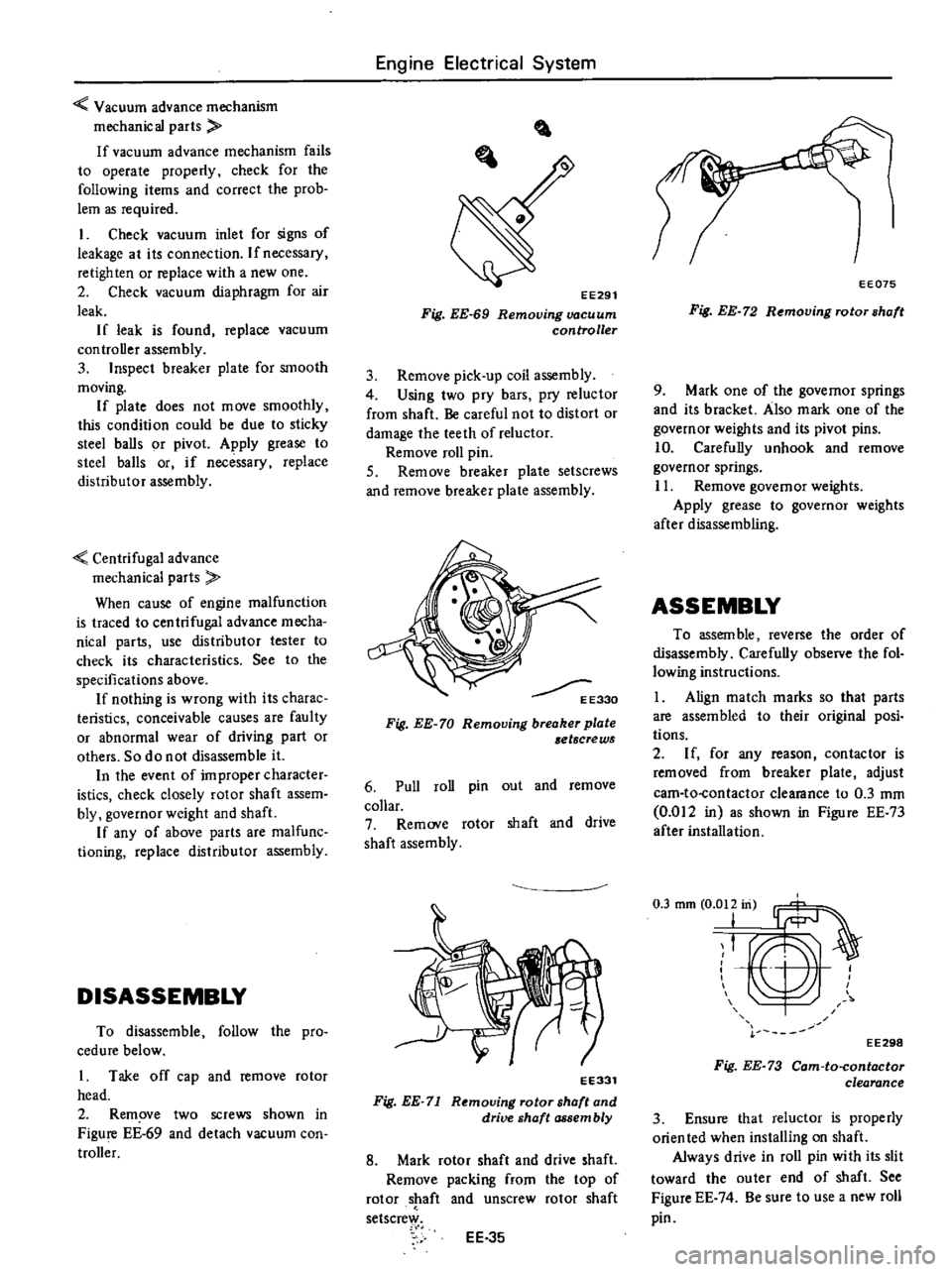
adjust
cam
to
contactor
clearance
to
0
3
mm
0
012
in
as
shown
in
Figure
EE
73
after
installation
T
EE298
Fig
EE
73
Cam
to
contactor
clearance
3
Ensure
that
reluctor
is
properly
orien
ted
when
installing
on
shaft
Always
drive
in
roll
pin
with
its
slit
toward
the
outer
end
of
shaft
See
Figure
EE
74
Be
sure
to
use
a
new
roll
pin
Page 223 of 537

DESCRIPTION
REMOVAL
AND
INSTAllATION
Removal
Installation
DESCRIPTION
The
clutch
is
a
single
dry
disc
type
CLUTCH
CLUTCH
CONTENTS
CL
2
Cl2
CL
2
CL
3
DISASSEMBLY
AND
ASSEMBLY
D
isassemb
I
y
Assembly
INSPECTION
CL
3
Cl3
CL
3
CL
4
using
a
diaphragm
spring
It
consists
of
the
clutch
disc
pressure
plate
dia
phragm
spring
thrust
rings
clutch
cover
I
and
clutch
release
bearing
e
M
0
s
8
o
8
l150
5
91
dia
225
8
86
dia
REMOVAL
AND
I
NSTALLATIO
Removal
1
Remove
transmission
from
ve
hicle
For
details
of
transmission
removal
refer
to
Transmission
Section
2
Insert
Clutch
Aligning
Bar
KV30100200
into
clutch
disc
hub
until
it
will
no
longer
go
It
is
im
A
u
o
6
o
C
62
2
44
dia
I
260
10
2
dia
CL231
Fig
CL
l
Construction
of
clutch
disc
and
COller
assembly
Unit
mm
in
portant
to
support
weight
of
clutch
disc
during
further
steps
See
Figure
CL
2
3
Loosen
six
screws
attaching
clutch
cover
to
flywheel
one
turn
at
a
time
each
un
til
spring
pressure
is
re
leased
Be
sure
to
turn
them
out
in
a
crisscross
fashion
Note
Exercise
special
care
to
avoid
grease
or
on
getting
on
clutch
linings
CL2
Fig
CL
2
Supporting
clutch
assembly
Page 238 of 537
REMOVAL
In
dismounting
transmission
from
the
vehicle
proceed
as
follows
I
Disconnect
battery
ground
cable
from
terminal
2
Place
transmission
control
lever
in
neutIal
position
3
Remove
E
ring
and
control
lever
pin
from
transmission
striking
rod
guide
and
remove
control
lever
See
Figure
MT
4
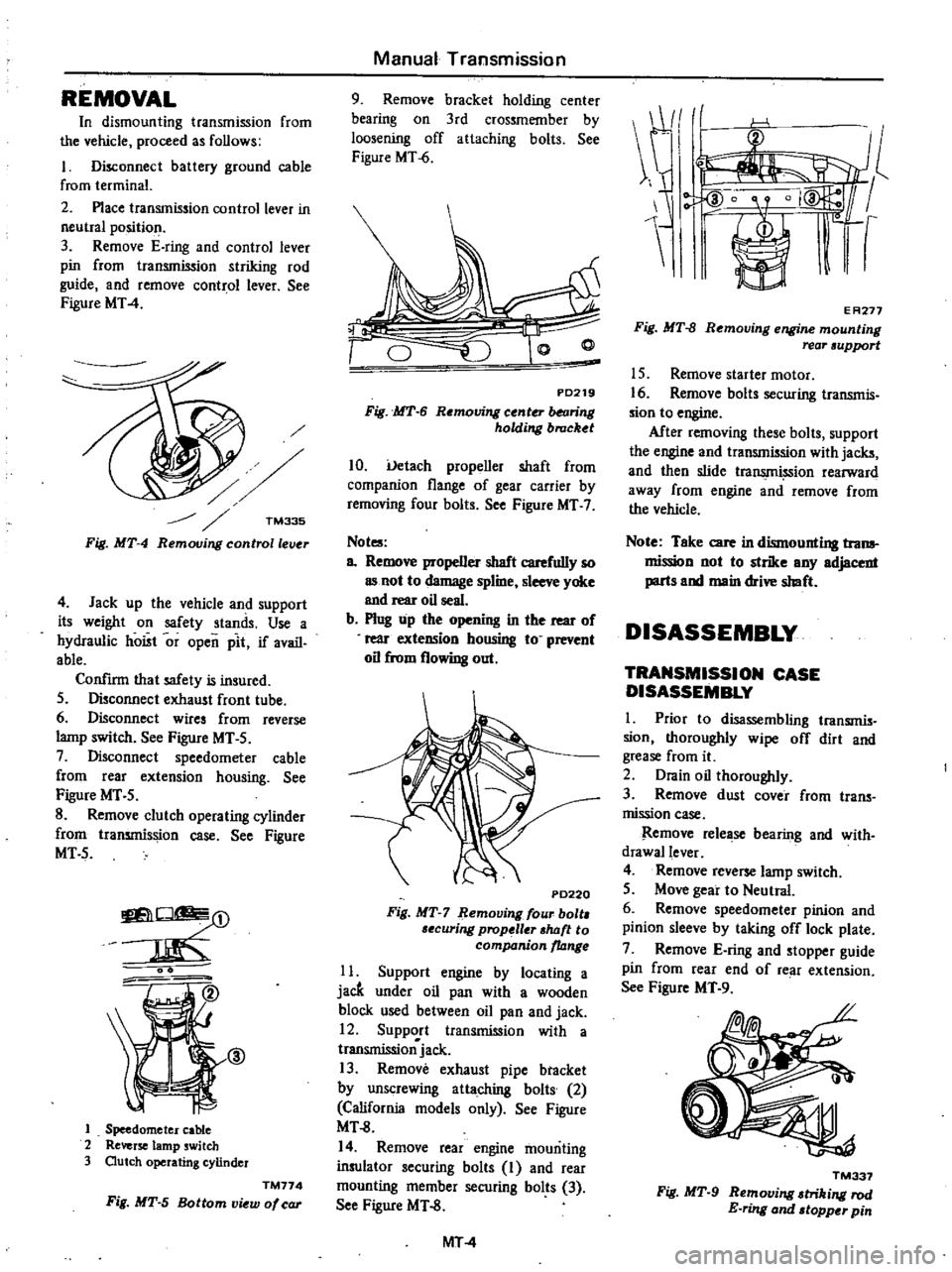
TM335
Fig
MT
4
Remouing
controllelJ
r
4
Jack
up
the
vehicle
and
support
its
weight
on
safety
stands
Use
a
hydraulic
hoist
or
open
pit
if
avail
able
Confirm
that
safety
is
insured
5
Disconnect
exhaust
front
tube
6
Disconnect
wires
from
reverse
lamp
switch
See
Figure
MT
5
7
Disconnect
speedometer
cable
from
rear
extension
housing
See
Figure
MT
5
8
Remove
clutch
operating
cylinder
from
transmission
case
See
Figure
MT5
O
m
J
@
1
Speedometer
cable
2
Reverse
lamp
switch
3
Outch
operating
cylinder
TM774
Fig
MT
5
Bottom
view
of
car
Manual
Transmission
9
Remove
bracket
holding
center
bearing
on
3rd
crossmember
by
loosening
off
attaching
bolts
See
Figure
MT
6
PD219
Fig
MT
6
Removing
center
balring
holding
brucket
10
Uetach
propeller
shaft
from
companion
flange
of
gear
carrier
by
removing
four
bolts
See
Figure
MT
7
Not
a
Remove
propeller
shaft
carefully
so
as
not
to
damage
spline
sleeve
yoke
and
rear
oil
seal
b
Plug
up
the
opening
in
the
rear
of
rear
exteDSion
housing
to
prevent
oil
from
flowing
out
P0220
Fig
MT
7
Remouing
four
bolt
6ecuring
prop
ller
shtJft
to
companion
ltJnge
11
Support
engine
by
locating
a
jacft
under
oil
pan
with
a
wooden
block
used
between
oil
pan
and
jack
12
Support
transmission
with
a
transmissionjack
13
Remove
exhaust
pipe
btacket
by
unscrewing
attaching
bolts
2
California
models
only
See
Figure
MT
8
14
Remove
rear
engine
mounting
insulator
securing
bolts
I
and
rear
mounting
member
securing
bolts
3
See
Figure
MT
8
MT
4
E
A277
Fig
MT
8
Removing
engine
mounting
rear
support
15
Remove
starter
motor
16
Remove
bolt
securing
transmis
sion
to
engine
After
removing
these
bolts
support
the
engine
and
transmission
with
jacks
and
then
slide
tra
ion
rearward
away
from
engine
and
remove
from
the
vehicle
Note
Take
care
in
dismounting
trona
mission
not
to
strike
any
adjacent
parts
and
main
drive
shaft
DISASSEMBLY
TRANSMISSION
CASE
DISASSEMBLY
I
Prior
to
disassembling
transmis
sion
thoroughly
wipe
off
dirt
and
grease
from
it
2
Drain
oil
thoroughly
3
Remove
dust
cover
from
trans
mission
case
Remove
release
bearing
and
with
drawallever
4
Remove
reverse
lamp
switch
5
Move
gear
to
Neutral
6
Remove
speedometer
pinion
and
pinion
sleeve
by
taking
off
lock
plate
7
Remove
E
ring
and
stopper
guide
pin
from
rear
end
of
re
ll
extension
See
Figure
MT
9
TM337
Fig
MT
9
Removing
triking
rod
E
ring
and
topper
pin
Page 297 of 537
Automatic
Transmission
REMOVAL
AND
INSTALLATION
TRANSMISSION
ASSEMBLY
REMOVAL
INSTALLATION
TRANSMISSION
ASSEMBLY
When
dismounting
the
automatic
transmission
from
a
vehicle
pay
at
tention
to
the
following
points
1
Before
dismounting
the
trans
mission
rigidly
inspecl
it
by
aid
of
the
Troubleshooting
Chart
and
dis
mount
it
only
when
considered
to
be
necessary
2
Dismount
the
transmission
with
utmost
care
and
when
mounting
observe
the
tightening
torque
indi
cated
on
another
table
not
to
exert
excessive
force
REMOVAL
In
dismounting
automatic
transmis
sion
from
vehicle
proceed
as
follows
I
Disconnect
battery
ground
cable
from
terminal
2
Disengage
torsion
shaft
from
ac
celerator
linkage
3
Jack
up
vehicle
and
support
its
weight
on
safety
stands
Recommend
a
hydraulic
hoist
or
open
pit
be
utilized
if
available
Make
sure
that
safety
is
insured
4
Remove
propeller
shaft
Note
Plug
up
the
opening
in
the
rear
extension
to
prevent
oil
from
flowing
out
5
Disconnect
front
exhaust
tube
6
Disconnect
selector
range
lever
from
manual
shaft
7
Disconnect
wire
connections
at
inhibitor
switch
CONTENTS
AT
33
AT
33
AT
33
TRANSMISSION
CONTROL
LINKAGE
REMOVAL
AND
INSTALLATION
ADJUSTMENT
AT
35
AT
35
AT
35
8
Disconnect
vacuum
tube
from
vacuum
diaphragm
and
wire
connee
lions
at
downshift
solenoid
9
Disconnect
speedometer
cable
from
rear
extension
10
Disconnect
oil
charging
pipe
II
Disconnect
oil
cooler
inlet
and
outlet
tubes
at
transmission
case
12
Support
engine
by
locating
a
jack
under
oil
pan
with
a
wooden
block
used
between
oil
pan
and
jack
Support
transmission
by
means
of
a
transmission
jack
13
Detach
converter
housing
dust
cover
Remove
bolts
securing
torque
converter
to
drive
plate
See
Figure
AT
4
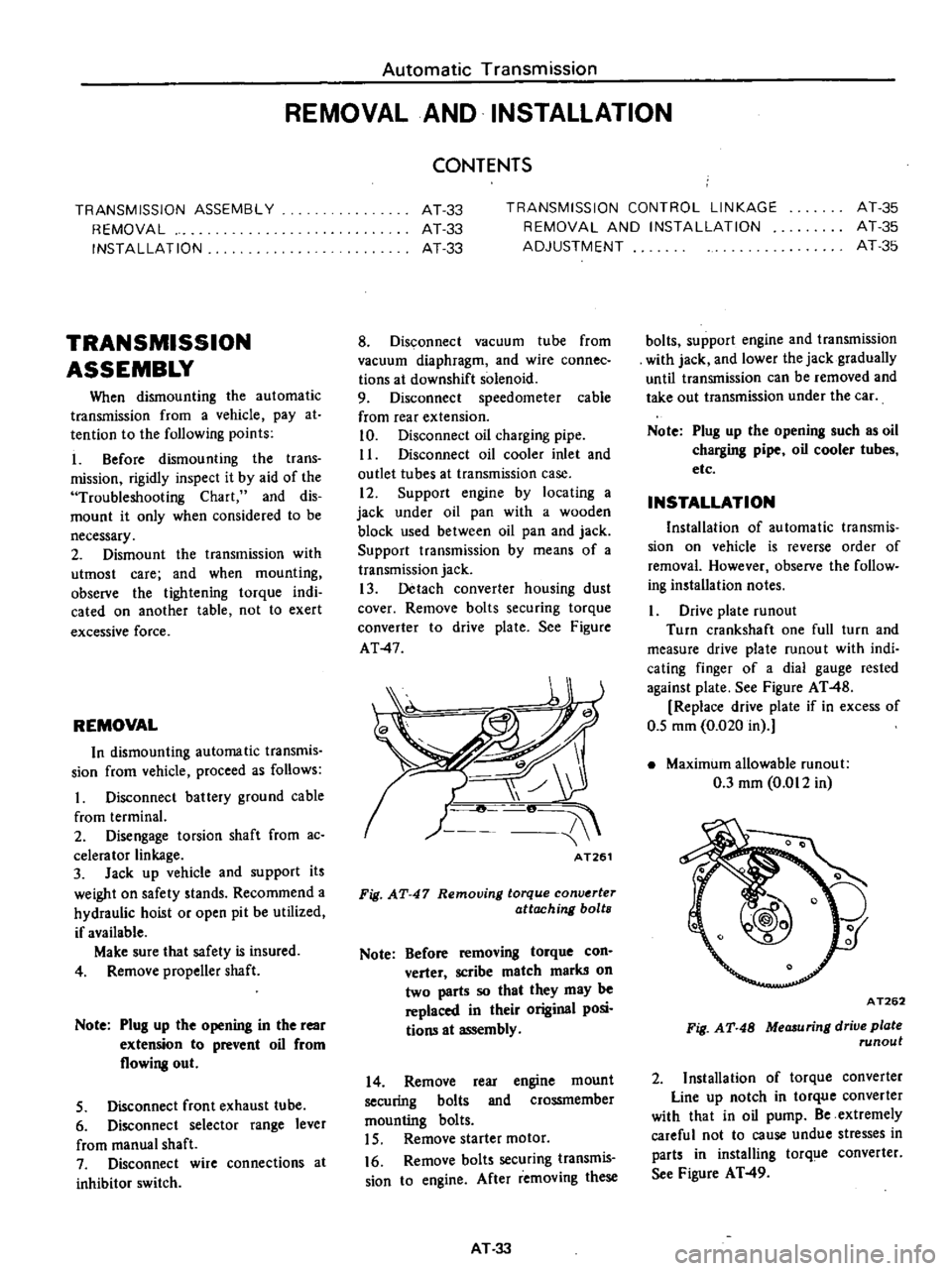
AT261
Fig
AT
47
Removing
torque
conv
rter
attaching
bolts
Note
Before
removing
torque
con
verter
scribe
match
marks
on
two
parts
so
that
they
may
be
replaced
in
their
original
posi
tions
at
assembly
14
Remove
rear
engine
mount
securing
bolts
and
crossmember
mounting
bolts
15
Remove
starter
motor
16
Remove
bolts
securing
transmis
sion
to
engine
After
removing
these
AT
33
bolts
support
engine
and
transmission
with
jack
and
lower
the
jack
gradually
until
transmission
can
be
removed
and
take
out
transmission
under
the
car
Note
Plug
up
the
opening
such
as
oil
charging
pipe
oil
cooler
tubes
etc
INSTALLATION
Installation
of
automatic
transmis
sion
on
vehicle
is
reverse
order
of
removal
However
observe
the
follow
ing
installation
notes
Drive
plate
runout
Turn
crankshaft
one
full
turn
and
measure
drive
plate
mnou
t
with
indi
cating
finger
of
a
dial
gauge
rested
against
plate
See
Figure
AT
48
Replace
drive
plate
if
in
excess
of
0
5
mm
0
020
in
Maximum
allowable
mnout
0
3
mm
0
012
in
A
T262
Fig
AT
48
MeCJ
uring
drive
plate
runout
2
Installation
of
torque
converter
Line
up
notch
in
torque
converter
with
that
in
oil
pump
Be
extremely
careful
not
to
cause
undue
stresses
in
parts
in
installing
torq
e
converter
See
Figure
AT
49
Page 332 of 537
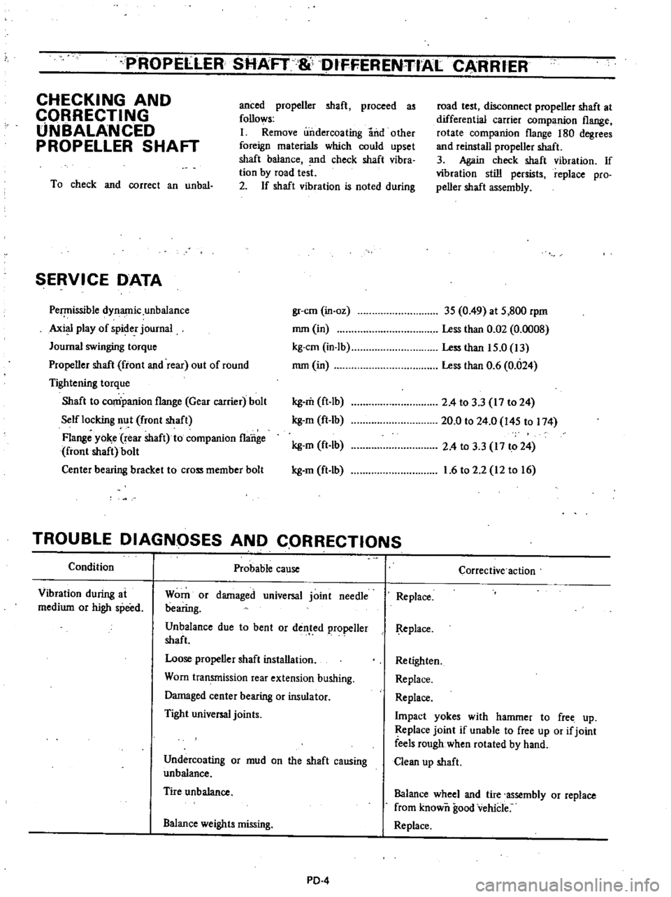
PROPELLER
SHAFT
8l
DIFFERENTIALCAAR
ER
CHECKING
AND
CQRRECTING
UNBALANCED
PROPELLER
SHAFT
anced
propeller
shaft
proceed
as
follows
I
Remove
undercoating
and
other
foreign
materials
which
could
upset
shaft
balance
and
check
shaft
vibra
tion
by
road
test
2
If
shaft
vibration
is
noted
during
To
check
and
correct
an
unbal
SERVICE
DATA
Pe
issible
dynamic
unbalance
Axi
play
of
spider
journal
Journal
swinging
torque
Propeller
shaft
front
and
rear
out
of
round
Tightening
torque
Shaft
to
conipanion
flange
Gear
carrier
bolt
Self
locking
nut
front
shaft
Flange
yo
e
rear
shaft
to
companion
flange
front
shaft
bolt
Center
bearing
bracket
to
cross
member
bolt
road
test
disconnect
propeller
shaft
at
differential
carrier
companion
flange
rotate
companion
flange
180
degrees
and
reinstall
propeller
shaft
3
Again
check
shaft
vibration
If
vibration
still
persists
replace
pro
peller
shaft
assembly
gr
cm
in
oz
3S
0
49
at
S
800
rpm
mm
in
Less
than
0
02
0
0008
kg
em
in
Ib
Less
than
IS
O
13
mm
in
Less
than
0
6
0
024
kg
m
ft
lb
kg
m
ft
Ib
kg
m
ft
lb
kg
m
ft
lb
2
4
to
3
3
17
to
24
20
0
to
24
0
l4S
to
174
2
4
to
3
3
17
to
24
1
6
to
2
2
12
to
16
TROUBLE
DIAGNOSES
AND
CQRRECTIONS
Condition
Probable
cause
Vibration
during
at
medium
or
high
speed
Worn
or
damaged
universal
joint
needle
bearing
Unbalance
due
to
bent
or
dented
propeller
shaft
Loose
propeller
shaft
installation
Worn
transmission
rear
extension
bushing
Damaged
center
bearing
or
insulator
Tight
universal
joints
Undercoating
or
mud
on
the
shaft
causing
unbalance
Tire
unbalance
Balance
weights
missing
PD
4
Corrective
action
Replace
I
l
eplace
Retighten
Replace
Replace
Impact
yokes
with
hammer
to
free
up
Replace
joint
if
unable
to
free
up
or
if
joint
feels
rough
when
rotated
by
hand
Clean
up
shaft
Balance
wheel
and
tire
assembly
or
replace
from
known
good
vehicle
Replace
Page 336 of 537
PROPElli
ER
SHAfT
DIFFERENTIAL
G
ARRIERf
Notes
a
PUller
should
be
handled
with
care
in
catchins
the
edge
of
bearing
inner
race
b
Be
careful
not
to
confuse
left
and
right
hand
parts
2
Remove
ring
gear
by
spreading
out
lock
strap
and
loosening
ring
gear
bolts
in
diagonally
3
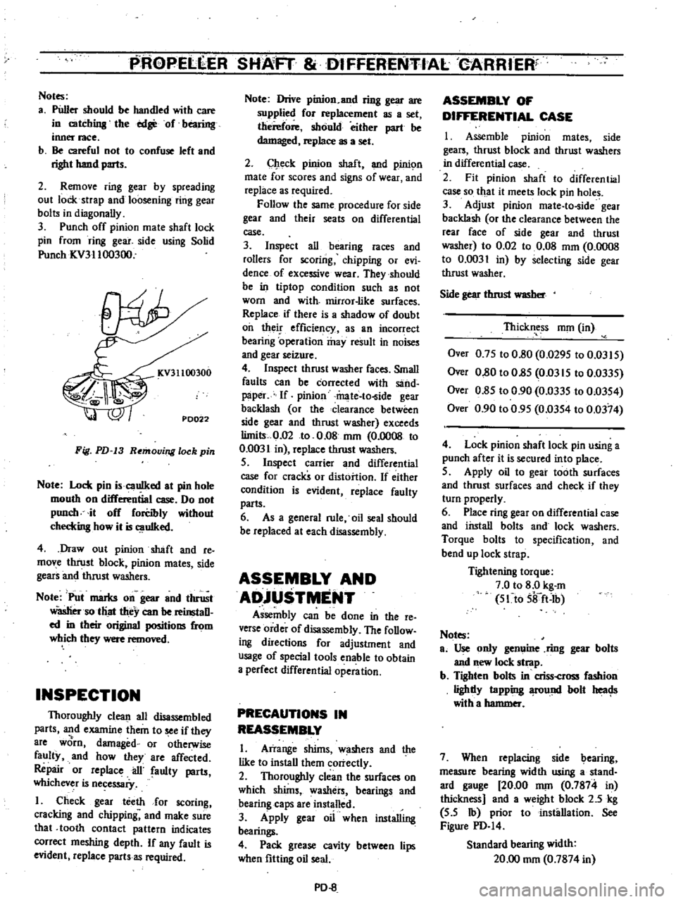
Punch
off
pinion
mate
shaft
lock
pin
from
ring
gear
side
using
Solid
Punch
ICV31100300
KV31100300
PD022
Fig
PD
13
Removing
lock
pin
Note
Lock
pin
i
cauIked
at
pin
hole
mouth
on
differential
case
Do
not
punch
it
off
forCibly
without
checkins
how
it
is
uIked
4
Draw
out
pinion
shaft
and
re
move
thrust
block
pinion
mates
side
gears
and
thrust
washers
Note
Put
marks
on
gear
and
thrust
Wasliersotliat
they
can
be
reinstaD
ed
in
their
original
positions
from
which
they
were
removed
INSPECTION
Thoroughly
clean
all
disassembled
parts
and
examine
them
to
see
if
they
8re
worn
damaged
or
otherwise
faulty
and
how
they
are
affected
Repair
or
replace
ail
faulty
parts
whichever
is
necessaiy
I
Check
gear
teeth
for
scoring
cracking
and
chipping
and
make
sure
that
tooth
contact
pattern
indicates
correct
meshing
depth
If
any
fault
is
evident
replace
parts
as
required
Note
Drive
pinion
and
ring
gear
are
supplied
for
replacement
as
a
set
therefore
should
either
part
be
damaged
replace
as
a
set
2
Check
pinion
shaft
and
pinic
m
mate
for
scores
and
signs
of
wear
and
replace
as
required
Follow
the
same
procedure
for
side
gear
and
their
seats
on
differential
case
3
Inspect
all
bearing
races
and
rollers
for
scoring
chipping
or
evi
dence
of
excessive
wear
They
should
be
in
tiptop
condition
such
as
not
worn
and
with
mirror
like
surfaces
Replace
if
there
is
a
shadow
of
doubt
oil
their
efficiency
as
an
incorrect
bearing
operation
may
result
in
noises
and
gear
seizure
4
Inspect
thrust
washer
faces
Small
faults
can
be
corrected
with
sand
paper
If
pinion
mate
to
ide
gear
backlash
or
the
clearance
between
side
gear
and
thrust
washer
exceeds
limits
0
02
to
0
08
nun
0
0008
to
0
0031
in
replace
thrust
washers
S
Inspect
carrier
and
differential
case
for
cracks
or
distortion
If
either
condition
is
evident
replace
faulty
parts
6
As
a
general
rule
oil
seal
should
be
replaced
at
each
disassembly
ASSEMBLY
AND
ADjUSTMENT
Assembly
can
be
done
in
the
reo
verse
order
of
disassembly
The
foDow
ing
directions
for
adjustment
and
usage
of
special
tools
enable
to
obtain
a
perfect
differential
operation
PRECAUTIONS
IN
REASSEMBLY
I
Arrange
shims
w
shers
and
the
like
to
install
them
correctly
2
Thoroughly
clean
the
surfaces
on
which
shims
washers
bearings
and
bearing
caps
are
installed
3
Apply
gear
oil
when
installing
bearings
4
Pack
grease
cavity
between
lips
when
fitting
oil
seal
PD
8
ASSEMBLY
OF
DIFFERENTIAL
CASE
I
Assemble
pinion
mates
side
gears
thrust
block
and
thrust
washers
in
differential
case
2
Fit
pinion
shaft
to
differential
case
so
that
it
meets
lock
pin
holes
3
Adjust
pinion
mate
to
ide
gear
backlash
or
the
clearance
between
the
rear
face
of
side
gear
and
thrust
washer
to
0
02
to
0
08
mOl
0
0008
to
0
0031
in
by
selecting
side
gear
thrust
washer
Side
gear
thrust
WlISber
Thickness
nun
in
Over
0
7S
to
0
80
0
029S
to
0
03IS
Over
0
80
to
O
8S
Om
IS
to
0
033S
Over
0
8S
to
0
90
0
033S
to
0
03S4
Over
0
90
to
0
9S
0
03S4
to
0
0374
4
Lock
pinion
shaft
lock
pin
using
a
punch
after
it
is
secured
into
place
S
Apply
oil
to
gear
tooth
surfaces
and
thrust
surfaces
and
check
if
they
turn
properly
6
Place
ring
gear
on
differential
case
and
install
bolts
and
lock
washers
Torque
bolts
to
specification
and
bend
up
lock
strap
Tightening
torque
7
0
to
8
0
kg
m
S1to
Sifft
Ib
Notes
ao
Use
only
genuine
ring
gear
bolts
and
new
lock
strap
b
Tighten
bolts
in
criss
cross
fashion
lighdy
tapping
fOund
bolt
heac
Js
with
a
hammer
7
When
replacing
side
bearing
measure
bearing
width
using
a
stand
ard
gauge
20
00
nun
0
7874
in
thickness
and
a
weight
block
2
5
kg
S
S
Ib
prior
to
installation
See
Figure
PD
I4
Standard
bearing
width
20
00
nun
0
7874
in
Page 358 of 537
s
Install
tension
rod
at
rear
end
tighten
nut
to
make
the
distance
of
rubber
bushing
to
be
33
4
mm
1
315
in
and
torque
lock
nut
to
1
6
to
2
2
kg
m
12
to
16
ft
lb
6
Install
tension
rod
bracket
to
chassis
frame
bracket
and
torque
nut
to
1
6
to
2
2
kg
m
12
to
16
ft
lb
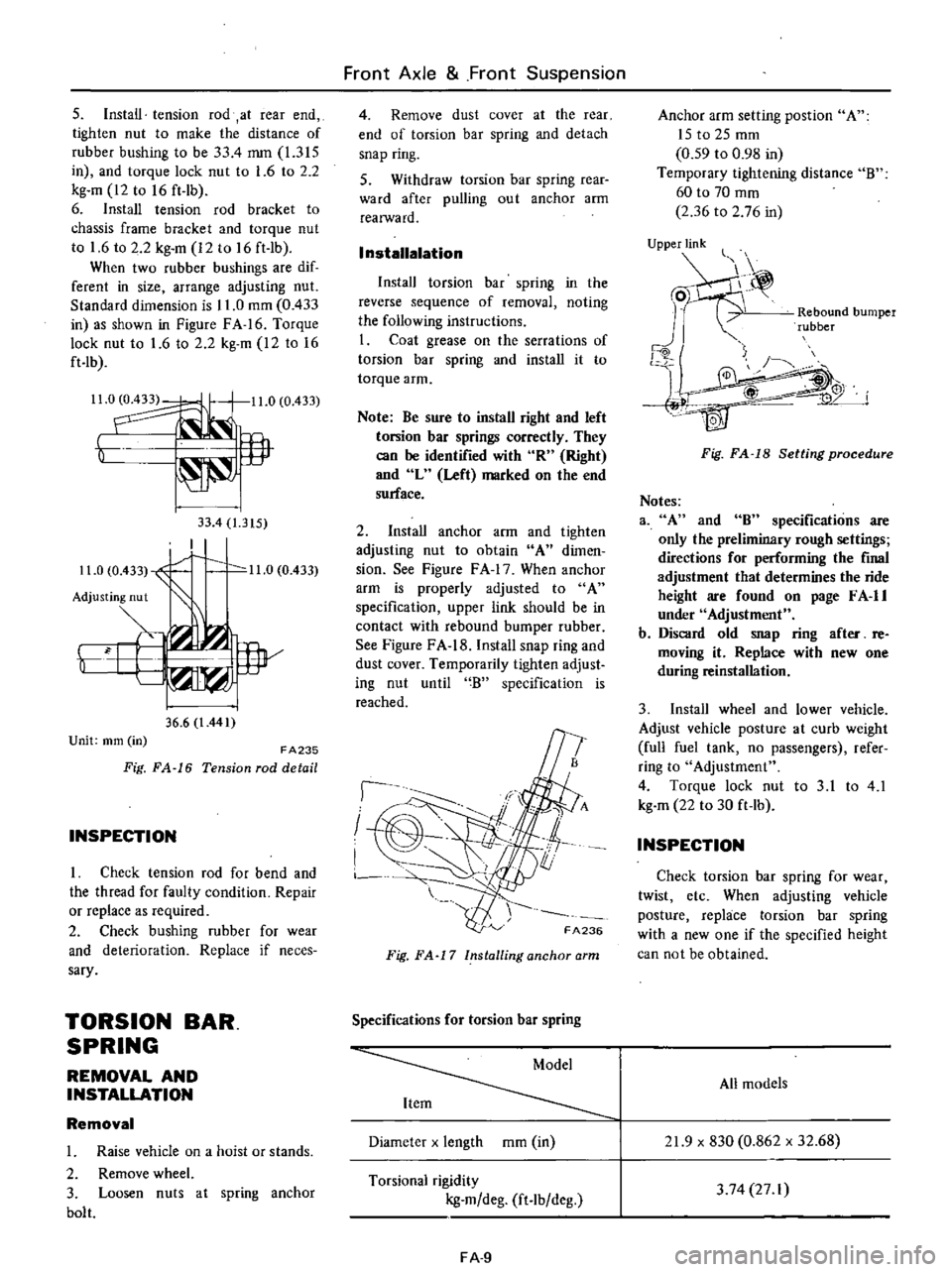
When
two
rubber
bushings
are
dif
ferent
in
size
arrange
adjusting
nut
Standard
dimension
is
11
0
mOl
0
433
in
as
shown
in
Figure
FA
16
Torque
lock
nut
to
1
6
to
2
2
kg
m
12
to
16
ft
lb
Il
0
11
0
0
433
t
lP
33
4
1
315
I
11
0
0
433
1
0
11
0
0
433
Adjusting
nut
Y
i
w
36
6
l
441
Unit
mm
in
FA235
Fig
FA
16
Tension
rod
detail
INSPECTION
I
Check
tension
rod
for
bend
and
the
thread
for
faulty
condition
Repair
or
replace
as
required
2
Check
bushing
rubber
for
wear
and
deterioration
Replace
if
neces
sary
TORSION
BAR
SPRING
REMOVAL
AND
INSTALLATION
Removal
1
Raise
vehicle
on
a
hoist
or
stands
2
Remove
wheel
3
Loosen
nuts
at
spring
anchor
bolt
Front
Axle
Front
Suspension
4
Remove
dust
cover
at
the
rear
end
of
torsion
bar
spring
and
detach
snap
ring
S
Withdraw
torsion
bar
spring
rear
ward
after
pulling
ou
t
anchor
arm
realWard
I
nstallalation
Install
torsion
bar
spring
in
the
reverse
sequence
of
removal
noting
the
following
instructions
I
Coat
grease
on
the
serrations
of
torsion
bar
spring
and
install
it
to
torque
arm
Note
Be
sure
to
install
right
and
left
torsion
bar
springs
correctly
They
can
be
identified
with
R
Right
and
L
Left
marked
on
the
end
surface
2
Install
anchor
arm
and
tighten
adjusting
nut
to
obtain
A
dimen
sion
See
Figure
F
A
17
When
anchor
arm
is
properly
adjusted
to
A
specification
upper
link
should
be
in
contact
with
rebound
bumper
rubber
See
Figure
FA
18
Install
snap
ring
and
dust
cover
Temporarily
tighten
adjust
ing
nut
until
B
specification
is
reached
I
I
I
FA236
Fig
FA
17
Installing
anchor
arm
Specifications
for
torsion
bar
spring
Diameter
x
length
mOl
in
Torsional
rigidity
kg
m
deg
ft
lb
deg
FA
9
Anchor
arm
setting
post
ion
A
ISt02Smm
0
59
to
0
98
in
Temporary
tightening
distance
B
60
to
70
mOl
2
36
to
2
76
in
UjPPje
Rebound
bumper
rubber
j
4W
Fig
FA
18
Setting
procedure
Notes
3
A
and
8
specifications
are
only
the
preliminary
rough
settings
directions
for
performing
the
final
adjustment
that
determines
the
ride
height
are
found
on
page
F
A
II
under
Adjustment
b
Discard
old
snap
ring
after
re
moving
it
Replace
with
new
one
during
reinstallation
3
Install
wheel
and
lower
vehicle
Adjust
vehicle
posture
at
curb
weight
full
fuel
tank
no
passengers
refer
ring
to
Adjustment
4
Torque
lock
nut
to
3
1
to
4
1
kg
m
22
to
30
ft
lb
INSPECTION
Check
torsion
bar
spring
for
wear
twist
etc
When
adjusting
vehicle
posture
replace
torsion
bar
spring
with
a
new
one
if
the
specified
height
can
not
be
obtained
All
models
21
9
x
830
0
862
x
32
68
3
74
27
I
Page 361 of 537
WHEEL
ALIGNMENT
Correct
front
wheel
alignment
attains
proper
vehicle
handling
charac
teristics
and
the
least
steering
effort
with
a
minimum
amount
of
tire
wear
Before
adjusting
front
wheel
align
ment
make
sure
to
carry
out
a
pre
liminary
inspection
of
the
front
end
parts
for
the
following
conditions
1
Tire
pressure
and
balance
2
Wheel
bearings
and
nuts
3
Steering
gear
play
4
Steering
gear
housing
at
frame
S
Steering
linkage
and
connections
6
Shock
absorber
action
When
using
the
equipment
for
front
wheel
alignment
inspection
follow
the
inst
c
tions
furnished
with
the
equip
ment
Furthennore
the
inspection
should
be
made
with
the
vehicle
level
and
at
curb
weight
Camber
and
caster
Measure
camber
and
caster
and
adjust
them
in
accordance
with
the
following
procedures
if
necessary
Both
camber
and
caster
are
ad
justed
by
increasing
and
decreasing
thickness
of
adjust
shim
inserted
be
tween
upper
link
spindle
and
upper
link
mounting
bracket
To
adjust
caster
make
a
difference
between
thickness
of
front
and
rear
shims
By
adding
a
shim
I
mm
0
039
in
at
front
side
caster
will
be
de
creased
by
33
At
the
same
time
camber
will
also
be
decreased
by
6
S
To
adjust
camber
add
or
remove
an
equal
amount
of
shims
to
front
and
rear
sides
By
adding
a
pack
of
shims
I
mOl
0
039
in
thick
at
both
sides
camber
will
be
decreased
by
13
Shims
are
available
in
I
mm
0
039
in
2
mOl
0
079
in
and
4
mOl
0
157
in
thickness
Front
Axle
Front
Suspension
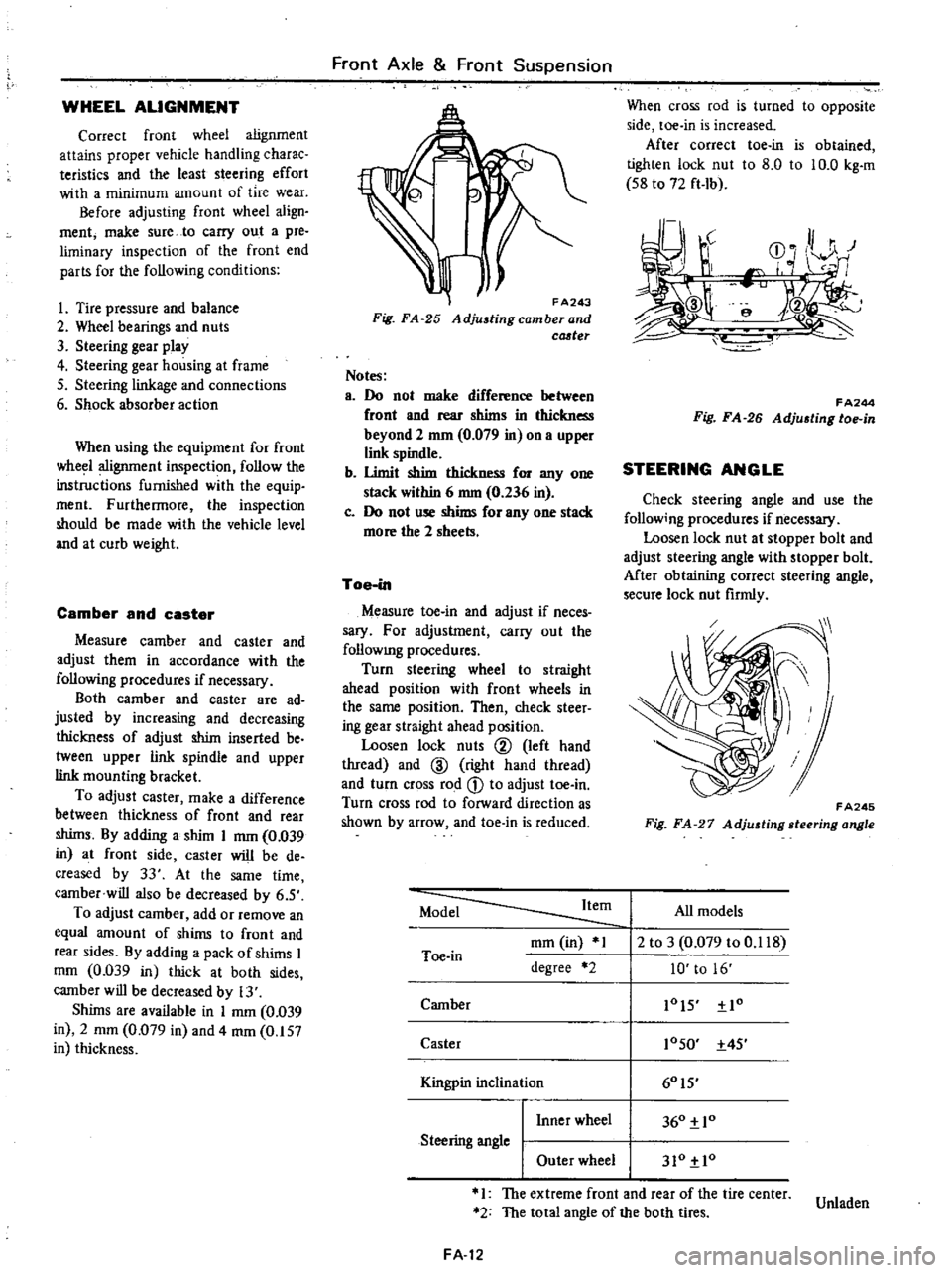
FA243
Fig
FA
25
Adjustingcamberand
cCJ
ter
Notes
a
Do
not
make
difference
between
front
and
rear
shims
in
thickness
beyond
2
mm
0
079
in
on
a
upper
link
spindle
b
Umit
shim
thickness
for
anyone
stack
within
6
nun
0
236
in
c
Do
not
use
shims
for
anyone
stack
more
the
2
sheets
Toe
in
Measure
toe
in
and
adjust
if
neces
sary
For
adjustment
carry
out
the
follOWIng
procedures
Turn
steering
wheel
to
straight
ahead
position
with
front
wheels
in
the
same
position
Then
check
steer
ing
gear
straight
ahead
position
Loosen
lock
nuts
@
left
hand
thread
and
ID
right
hand
thread
and
turn
cross
rod
CD
to
adjust
toe
in
Turn
cross
rod
to
forward
direction
as
shown
by
arrow
and
toe
in
is
reduced
When
cross
rod
is
turned
to
opposite
side
toe
in
is
increased
After
correct
toe
in
is
obtained
tighten
lock
nut
to
8
0
to
10
0
kg
m
S8
to
72
ft
Ib
r
J
r
CD
0
HI
r
I
e
f
FA244
Fig
FA
26
Adju6ting
toe
in
STEERING
ANGLE
Check
steering
angle
and
use
the
follow
ng
procedures
if
necessary
Loosen
lock
nut
at
stopper
bolt
and
adjust
steering
angle
with
stopper
bolt
Mter
obtaining
correct
steering
angle
secure
lock
nut
firmly
FA245
Fig
FA
27
Adjusting
steering
angle
Model
Item
All
models
mOl
in
1
2
to
3
0
079
to
0
118
Toe
in
degree
2
10
to
16
Camber
lOIS
Io
Caster
10SO
4S
I
60IS
Kingpin
inc
inal10n
I
Inner
wheel
360
10
Steering
angle
I
Outer
wheel
310
10
1
The
extreme
front
and
rear
of
the
tire
center
Unladen
2
The
total
angle
of
the
both
tires
FA
12