weight DATSUN PICK-UP 1977 Owner's Manual
[x] Cancel search | Manufacturer: DATSUN, Model Year: 1977, Model line: PICK-UP, Model: DATSUN PICK-UP 1977Pages: 537, PDF Size: 35.48 MB
Page 369 of 537
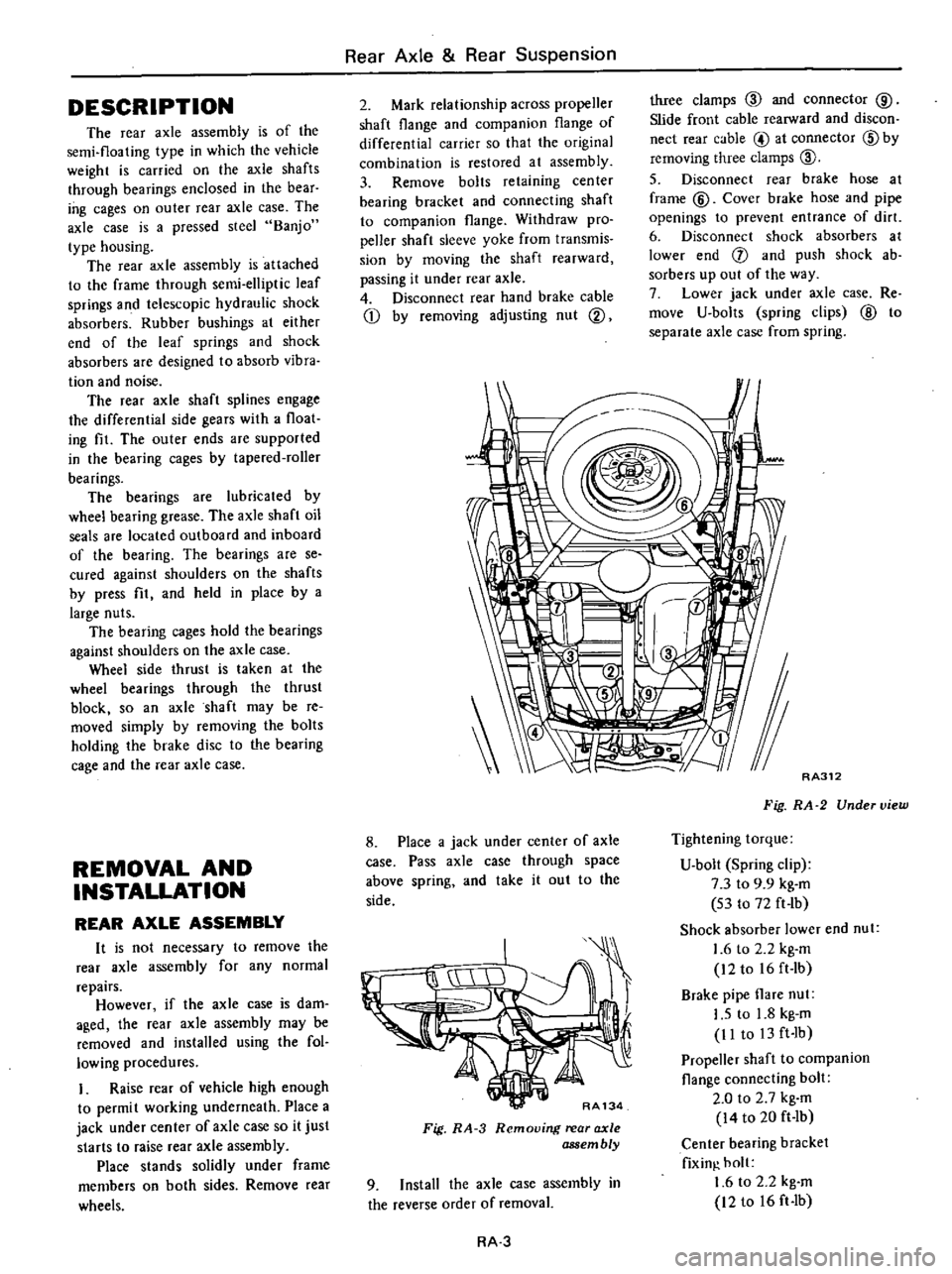
DESCRIPTION
The
rear
axle
assembly
is
of
the
semi
floating
type
in
which
the
vehicle
weight
is
carried
on
the
axle
shafts
through
bearings
enclosed
in
the
bear
ing
cages
on
outer
rear
axle
case
The
axle
case
is
a
pressed
steeJ
Banjo
type
housing
The
rear
axle
assembly
is
attached
to
the
frame
through
semi
elliptic
leaf
springs
and
telescopic
hydraulic
shock
absorbers
Rubber
bushings
at
either
end
of
the
leaf
springs
and
shock
absorbers
are
designed
to
absorb
vibra
tion
and
noise
The
rear
axle
shaft
splines
engage
the
differential
side
gears
with
a
float
ing
fit
The
outer
ends
are
supported
in
the
bearing
cages
by
tapered
roller
bearings
The
bearings
are
lubricated
by
wheel
bearing
grease
The
axle
shaft
oil
seals
are
located
outboard
and
inboard
of
the
bearing
The
bearings
are
se
cured
against
shoulders
on
the
shafts
by
press
fit
and
held
in
place
by
a
large
nuts
The
bearing
cages
hold
the
bearings
against
shoulders
on
the
axle
case
Whee
side
thrust
is
taken
at
the
wheel
bearings
through
the
thrust
block
so
an
axle
shaft
may
be
re
moved
simply
by
removing
the
bolts
holding
the
brake
disc
to
the
bearing
cage
and
the
rear
axle
case
REMOVAL
AND
INSTALLATION
REAR
AXLE
ASSEMBLY
It
is
not
necessary
to
remove
the
reaT
axle
assembly
for
any
normal
repairs
However
if
the
axle
case
is
dam
aged
the
rear
axle
assembly
may
be
removed
and
installed
using
the
fol
lowing
procedures
I
Raise
rear
of
vehicle
high
enough
to
permi
t
working
underneath
Place
a
jack
under
center
of
axle
case
so
it
just
starts
to
raise
rear
axle
assembly
Place
stands
solidly
under
frame
members
on
both
sides
Remove
rear
wheels
Rear
Axle
Rear
Suspension
2
Mark
relationship
across
propeller
shaft
flange
and
companion
flange
of
differential
carrier
so
that
the
original
combination
is
restored
at
assembly
3
Remove
bolts
retaining
center
bearing
bracket
and
connecting
shaft
to
companion
flange
Withdraw
pro
peller
shaft
sleeve
yoke
from
transmis
sion
by
moving
the
shaft
rearward
passing
it
under
rear
axle
4
Disconnect
rear
hand
brake
cable
Q
by
removing
adjusting
nut
@
three
clamps
ID
and
connector
@
Slide
front
cable
rearward
and
discon
nect
rear
cable
@
at
connector
ID
by
removing
three
clamps
ID
5
Disconnect
rear
brake
hose
at
frame
@
Cover
brake
hose
and
pipe
openings
to
prevent
entrance
of
dirt
6
Disconnect
shock
absorbers
at
lower
end
f
and
push
shock
ab
sorbers
up
out
of
the
way
7
Lower
jack
under
axle
case
Re
move
U
bolts
spring
clips
@
to
separate
axle
case
from
spring
8
Place
a
jack
under
center
of
axle
case
Pass
axle
case
through
space
above
spring
and
take
it
out
to
the
side
RA134
Fig
RA
3
Removing
rear
axle
assembly
9
Install
the
axle
case
assembly
in
the
reverse
order
of
removal
RA
3
RA312
Fig
RA
2
Under
view
Tightening
torque
U
bolt
Spring
clip
7
3
to
9
9
kg
m
53
to
72
ft
lb
Shock
absorber
lower
end
nut
1
6
to
2
2
kg
m
12to
16ft
Ib
Brake
pipe
flare
nut
I
S
to
1
8
kg
m
II
to
13
ft
Ib
Propeller
shaft
to
companion
flange
connecting
bolt
2
0
to
2
7
kg
m
14
to
20
ft
Ib
Center
bearing
bracket
fixin
holt
1
6
to
2
2
kg
m
12
to
16
ft
Ib
Page 372 of 537
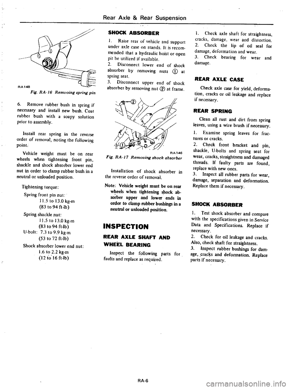
RA148
Fig
RA
16
Remvoing
spring
pin
6
Remove
rubber
bush
in
spring
if
necessary
and
install
new
bush
Coat
rubber
hush
with
a
soapy
solution
prior
to
assembly
InstaH
rear
spring
in
the
reverse
order
of
removal
noting
the
following
poinc
Vehicle
weight
must
be
on
rear
wheels
when
tightening
front
pin
shackle
and
shock
absorber
lower
end
nut
in
order
to
clamp
rubber
bush
in
a
neutral
or
unloaded
position
Tightening
torque
Spring
fTont
pin
nut
11
5
to
13
0
kg
m
83
to
94
ft
Ib
Spring
shackle
nut
11
5
to
13
0
kg
m
83
t094
ft
b
U
bolt
7
3
to
9
9
kg
m
S3
to
72
ft
lb
Shock
absorber
lower
end
nut
1
6
to
2
2
kg
m
12
to
16
ft
lb
Rear
Axle
Rear
Suspension
SHOCK
ABSORBER
Raise
rear
of
vehicle
and
support
under
axle
case
on
stands
It
is
recom
mended
that
a
hydraulic
hoist
or
open
pit
be
utilized
if
available
2
Disconnect
lower
end
of
shock
absorber
by
removing
nuts
Q
at
spring
seat
3
Disconnect
upper
end
of
shock
absorber
by
removing
nut
2
at
frame
RA146
Fig
RA
J
7
Removing
shock
absorber
Installation
of
shock
absorber
in
the
reverse
order
of
removal
Note
Vehicle
weight
must
be
on
Tear
wheels
when
tigtrtening
shock
ab
sorber
upper
and
lower
ends
in
order
to
clamp
rubber
bushings
in
a
neutral
or
unloaded
position
INSPECTION
REAR
AXLE
SHAFT
AND
WHEEL
BEARING
Inspect
the
following
parts
for
faults
and
replace
as
required
RA
6
I
Check
axle
shaft
for
straightness
cracks
damage
wear
and
distortion
2
Check
the
lip
of
oil
seal
for
damage
deformation
and
wear
3
Check
bearing
for
wear
and
damage
REAR
AXLE
CASE
Check
axle
case
for
yield
deforma
tion
cracks
or
oil
leakage
and
replace
if
necessary
REAR
SPRING
Clean
all
rust
and
dirt
from
spring
leaves
using
a
wire
brush
if
necessary
1
Examine
spring
leaves
for
frae
tures
or
cracks
2
Check
front
bracket
and
pin
shackle
U
bolts
and
spring
seat
for
wear
cracks
straightness
and
damaged
threads
If
faulty
parts
are
found
replace
with
new
ones
3
Inspect
all
rubber
parts
for
wear
damage
separation
and
deformation
Replace
them
if
necessary
SHOCK
ABSORBER
I
Test
shock
absorber
and
compare
with
the
specifications
given
in
Service
Data
and
Specifications
Replace
if
necessary
2
Check
for
oil
leakage
and
cracks
Also
check
shaft
for
straightness
3
Inspect
rubber
bushings
for
dam
age
cracl
s
and
deformation
Replace
parts
if
necessary
Page 383 of 537
REMOVAL
1
Removing
flare
nuts
on
both
ends
and
clips
effects
the
removal
of
brake
tube
and
brake
hose
2
Rear
brake
hose
can
be
removed
by
disconnecting
the
tube
and
then
turning
round
the
hose
Note
When
removing
brake
tubes
and
hoses
use
Flare
Nut
Torque
Wrench
GG943IOOOO
Never
use
an
OpeD
end
or
an
adjust
able
wrench
INSPECTION
1
Examine
all
hoses
for
swell
rubbing
marks
or
ozone
cracking
re
placing
those
found
with
any
of
above
badly
beyond
use
Also
inspect
end
fittings
and
be
sure
that
no
fluid
leak
through
staked
end
has
taken
place
replace
if
necessary
Hose
with
badly
rusted
fitting
should
also
be
replaced
with
a
new
one
2
Clean
all
tubes
to
remove
dust
and
dirt
with
isopropyl
alcohol
check
ing
for
collapse
wear
cracking
swell
or
rusting
Replace
if
foun
d
with
any
of
wove
Use
care
not
to
damage
brake
tubes
while
operation
Check
if
tubes
are
clamped
secure
ly
Mter
all
brake
lines
have
been
installed
retighten
aU
connections
if
necessary
to
assist
in
obtaining
correct
torque
In
retightening
at
front
wheel
cylinder
first
remove
hose
clamp
and
loosen
flare
nut
on
opposite
side
to
avoid
twisting
hose
Hold
pedal
as
far
downward
as
possible
80
kg
176
lb
or
more
examining
evidence
as
to
whether
fluid
is
leaking
through
brake
lines
or
con
nections
Leakage
in
any
manner
can
not
be
permitted
here
In
case
fluid
leaks
tightening
to
specified
torque
tighten
additionally
up
to
2
5
kg
m
J
8
ft
lb
Under
no
circumstances
should
not
be
tightened
over
2
5
kg
m
18
ft
Ib
torque
since
this
elongates
end
fitting
making
it
impossible
to
reuse
brake
tube
Under
no
circumstances
should
rear
brake
hose
and
3
way
connector
be
retightened
over
specified
torques
In
Brake
System
stead
replace
copper
washer
with
a
new
one
after
checking
for
sign
of
damage
on
seating
surface
Never
reuse
an
old
copper
washer
INSTALLATION
Brake
hose
Front
brake
hose
In
installing
brake
hose
first
jack
up
vehicle
to
take
off
the
weight
of
vehicle
from
wheels
so
that
suspension
is
in
rebound
Steering
wheel
should
also
be
kept
in
straight
ahead
position
To
connect
brake
line
first
connect
brake
hose
to
wheel
cylinder
with
the
specified
torque
Tightening
torque
1
7
to
2
0
kg
m
12
to
14
ft
Ib
Then
secure
brake
hose
to
the
bracket
with
lock
plate
so
as
not
to
twist
or
abnormally
bend
the
hose
Note
After
connecting
brake
hose
at
both
eiuIs
pay
keen
attention
not
to
twist
the
hose
when
additional
tightening
is
required
Fig
BR
12
Front
brake
hose
Rear
brake
hose
First
secure
rear
brake
hose
to
3
way
connector
on
rear
axle
case
to
the
specifications
Mter
connecting
hose
do
not
tighten
it
at
3
way
connector
additionally
since
this
oper
ation
causes
hose
to
be
twisted
Tightening
torque
I
7
to
2
0
kg
m
12
to
14
ft
Ib
BR
8
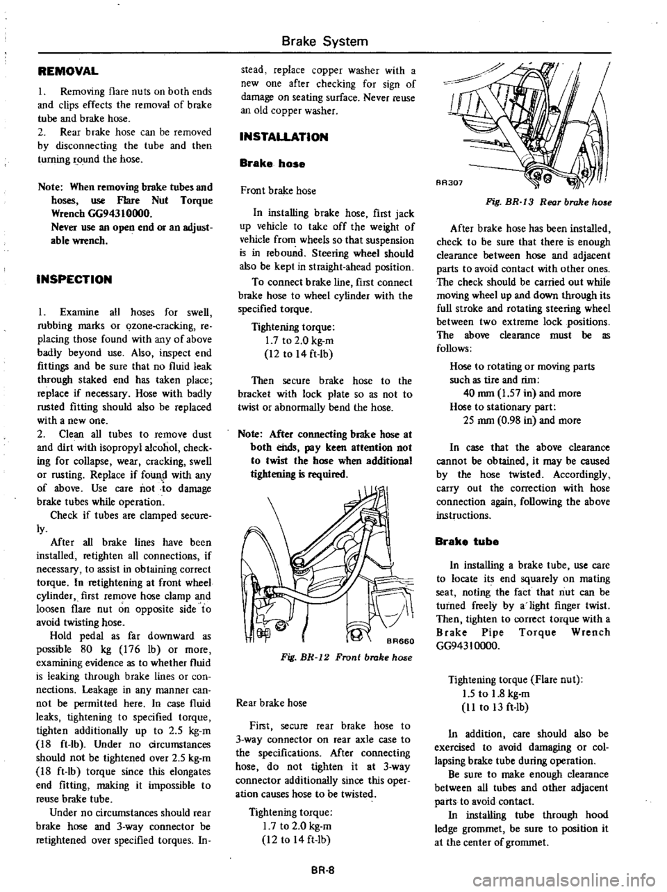
Fig
BR
13
Rear
brake
ho
e
After
brake
hose
has
been
installed
check
to
be
sure
that
there
is
enough
clearance
between
hose
and
adjacent
parts
to
avoid
contact
with
other
ones
The
check
should
be
carried
out
while
moving
wheel
up
and
down
through
its
full
stroke
and
rotating
steering
wheel
between
two
extreme
lock
positions
The
wow
clearance
must
be
as
follows
Hose
to
rotating
or
mOving
parts
such
as
tire
and
rim
40
mm
1
57
in
and
more
Hose
to
stationary
part
2S
mm
0
98
in
and
more
In
case
that
the
above
clearance
cannot
be
obtained
it
may
be
caused
by
the
hose
twisted
Accordingly
carry
out
the
correction
with
hose
connection
again
following
the
above
instructions
Brake
tube
In
installing
a
brake
tube
use
care
to
locate
its
end
squarely
on
mating
seat
noting
the
fact
that
nut
can
be
turned
freely
by
a
light
finger
twist
Then
tighten
to
correct
torque
with
a
Brake
Pipe
Torque
Wrench
GG943
10000
Tightening
torque
Flare
nut
1
5
to
1
8
kg
m
11
to
13
ft
Ib
In
addition
care
should
also
be
exercised
to
avoid
damaging
or
col
lapsing
brake
tube
during
operation
Be
sure
to
make
enough
clearance
between
all
tubes
and
other
adjacent
parts
to
avoid
contact
In
installing
tube
through
hood
ledge
grommet
be
sure
to
position
it
at
the
center
of
grommet
Page 404 of 537
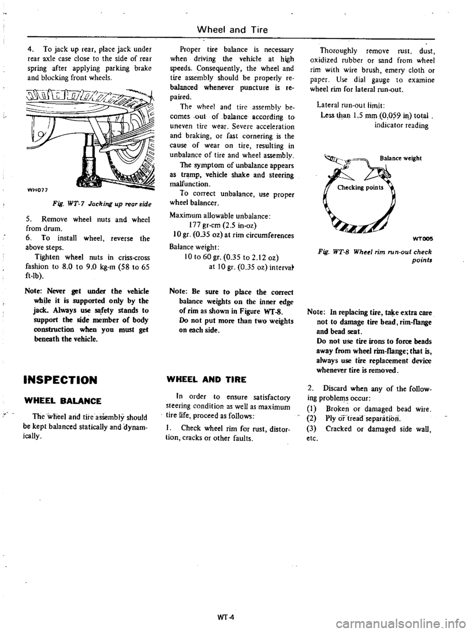
4
To
jack
up
rear
place
jack
under
rear
axle
case
close
to
the
side
of
rear
spring
after
applying
parking
brake
and
blocking
front
wheels
WH077
Fig
WT
7
Jacking
up
rear
side
S
Remove
wheel
nuts
and
wheel
from
drum
6
To
install
wheel
reverse
the
above
steps
Tighten
wheel
nuts
in
criss
cross
fashion
to
8
0
to
9
0
kg
m
S8
to
6S
ft
Ib
Note
Nerer
get
under
the
vehicle
while
it
is
supported
only
by
the
jack
Always
use
S8
fety
stands
to
support
the
side
member
of
body
construction
when
you
must
get
beneath
the
vehicle
INSPECTION
WHEEL
BALANCE
The
wheel
arid
tire
asSembly
should
be
kept
balanced
statically
and
dynam
ically
Wheel
and
Tire
Proper
tire
balance
is
necessary
when
driving
the
vehicle
at
high
speeds
Consequently
the
wheel
and
tire
assembly
should
be
properly
re
balanced
whenever
puncture
is
re
paired
The
wheel
and
tire
assembly
be
comes
out
of
ba1ance
according
to
uneven
tire
wear
Severe
acceleration
and
braking
or
fast
cornering
is
the
cause
of
wear
on
tire
resulting
in
unbalance
of
tire
and
wheel
assembly
The
symptom
of
unbalance
appears
as
tramp
vehicle
shake
and
steering
malfunction
To
correct
unbalance
use
proper
wheel
balancer
Maximum
allowable
unbalance
177
gr
cm
2
5
in
oz
10
gr
O
3S
oz
at
rim
circumferences
Balance
weight
10
to
60
gr
O
3S
to
2
12
oz
at
10
gr
0
3S
oz
intervat
Note
Be
sure
to
place
the
correct
balance
weights
on
the
inner
edge
of
rim
as
shown
in
Figure
WT
S
00
not
put
more
than
two
weights
on
each
side
WHEEL
AND
TIRE
In
order
to
ensure
satisfactory
steering
condition
as
well
as
maximum
tire
life
proceed
as
follows
Check
wheel
rim
for
rust
distor
tion
cracks
or
other
faults
WT
4
Thoroughly
remove
rust
dust
oxidized
rubber
or
sand
from
wheel
rim
with
wire
brush
emery
cloth
or
paper
Use
dial
gauge
to
examine
wheel
rim
for
lateral
run
out
Lateral
run
Qut
limit
Less
tltan
1
5
mOl
0
059
il
total
indicator
reading
WTOO5
Fig
WT
B
Whetl
rim
run
out
check
points
Note
In
replacing
tire
t
e
extra
care
not
to
damage
tire
bead
rim
flange
and
bead
seat
Do
not
use
tire
irons
to
force
beads
away
from
wheel
rim
flange
that
is
always
use
tire
replacement
device
whenever
tire
is
removed
2
Discard
when
any
of
the
follow
ing
problems
occur
1
Broken
or
damaged
bead
wire
2
Ply
o
treairsepanitiori
3
Cracked
or
damaged
side
wall
etc
Page 410 of 537
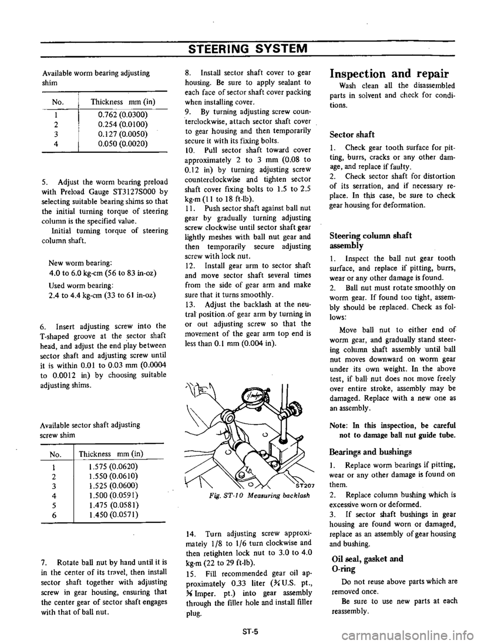
Available
worm
bearing
adjusting
shim
No
Thickness
mOl
in
I
0
762
0
0300
2
0
2S4
0
0100
3
0
127
0
0050
4
O
OSO
0
0020
5
Adjust
the
worm
bearing
preload
with
Preload
Gauge
ST3127S000
by
selecting
suitable
bearing
shims
so
that
the
initial
turning
torque
of
steering
column
is
the
specified
value
Initial
turning
torque
of
steering
column
shaft
New
worm
bearing
4
0
to
6
0
kg
em
S6
to
83
in
oz
Used
worm
bearing
2
4
to
4
4
kg
em
33
to
61
in
oz
6
Insert
adjusting
screw
into
the
T
shaped
groove
at
the
sector
shaft
head
and
adjust
the
end
play
between
sector
shaft
and
adjusting
screw
until
it
is
within
0
01
to
0
03
mm
0
0004
to
0
0012
in
by
choosing
suitable
adjusting
shims
Available
sector
shaft
adjusting
screw
shim
No
Thickness
mOl
in
I
1
57S
0
0620
2
1
550
0
0610
3
1
525
0
0600
4
I
S00
0
OS91
S
1
475
0
0581
6
I
4S0
0
0571
7
Rotate
ball
nut
by
hand
until
it
is
in
the
center
of
its
trovel
then
install
sector
shaft
together
with
adjusting
screw
in
gear
housing
ensuring
that
the
center
gear
of
sector
shaft
engages
with
that
of
ball
nut
STEERING
SYSTEM
8
Install
sector
shaft
cover
to
gear
housing
Be
sure
to
apply
sealant
to
each
face
of
sector
shaft
cover
packing
when
installing
cover
9
By
turning
adjusting
screw
coun
terclockwise
attach
sector
shaft
cover
to
gear
housing
and
then
temporarily
secure
it
with
its
fixing
bolts
10
Pull
sector
shaft
toward
cover
approximately
2
to
3
mOl
0
08
to
0
12
in
by
turning
adjusting
screw
counterclockwise
and
tighten
sector
shaft
cover
fixing
bolts
to
l
S
to
2
5
kg
m
11
to
18
ft
Ib
II
Push
sector
shaft
against
ball
nut
gear
by
gradually
turning
adjusting
screw
clockwise
until
sector
shaft
gear
lightly
meshes
with
ball
nut
gear
and
then
temporarily
secure
adjusting
screw
with
lock
nut
12
Install
gear
arm
to
sector
shaft
and
move
sector
shaft
several
times
from
the
side
of
gear
arm
and
make
sure
that
it
turns
smoothly
13
Adjust
the
backlash
at
the
neu
tral
position
of
gear
arm
by
turning
in
or
out
adjusting
screw
so
that
the
movement
of
the
gear
arm
top
end
is
less
than
0
1
mOl
0
004
in
0
ST207
Fig
ST
10
Mea
uring
backlash
14
Turn
adjusting
screw
approxi
mately
1
8
to
1
6
turn
clockwise
and
then
retighten
lock
nut
to
3
0
to
4
0
kg
m
22
to
29
ft
Ib
IS
Fill
recommended
gear
oil
ap
proximately
0
33
liter
X
U
S
pI
X
Imper
pt
into
gear
assembly
through
the
filler
hole
and
install
filler
plug
ST
5
Inspection
and
repair
Wash
clean
all
the
disassembled
parts
in
solvent
and
check
for
condi
tions
Sector
shaft
1
Check
gear
tooth
surface
for
pit
ting
burrs
cracks
or
any
other
dam
age
and
replace
if
faulty
2
Check
sector
shaft
for
distortion
of
its
serration
and
if
necessary
re
place
In
this
case
be
sure
to
check
gear
housing
for
deformation
Steering
column
shaft
assembly
1
Inspect
the
ball
nut
gear
tooth
surface
and
replace
if
pitting
burrs
wear
or
any
other
damage
is
found
2
Ball
nut
must
rotate
smootWy
on
worm
gear
If
found
too
tight
assem
bly
should
be
replaced
Check
as
fol
lows
Move
ball
nut
to
either
end
of
worm
gear
and
gradually
stand
steer
ing
column
shaft
assembly
until
ball
nut
moves
downward
on
worm
gear
under
its
own
weight
In
the
above
test
if
ball
nut
does
no
move
freely
over
entire
stroke
assembly
may
be
damaged
Replace
with
a
new
one
as
an
assembly
Note
In
this
inspection
be
careful
not
to
dama
e
ball
nut
guide
tube
Bearings
and
bushings
I
Replace
worm
bearings
if
pitting
wear
or
any
other
damage
is
found
on
them
2
Repiace
column
bushing
which
is
excessive
worn
or
deformed
3
If
sector
shaft
bushings
in
gear
housing
are
found
worn
or
damaged
replace
as
an
assembly
of
gear
housing
and
bushing
Oil
seal
gasket
and
O
ring
Do
not
reuse
above
parts
which
are
removed
once
Be
sure
to
use
new
parts
at
each
reassembly
Page 436 of 537

@
I
r
L
c
@
DESCRIPTION
The
door
consists
of
inner
and
outer
panels
welded
together
to
form
a
rigid
structure
The
curved
glass
provides
greater
shoulder
room
A
door
that
incorporates
a
ventila
tor
window
is
also
available
as
an
option
The
weatherstrip
is
inserted
into
the
groove
on
the
door
sash
side
and
is
attached
by
clips
on
the
door
side
DOOR
REMOVAL
AND
INSTALLATION
I
With
door
in
full
open
position
place
a
garage
jack
or
stand
beneath
door
to
support
its
weight
when
bolts
are
removed
Place
rag
between
door
and
jack
or
stand
to
avoid
damaging
painted
surface
Body
Frame
CD
1
@
@
ID
@
AJ
@
@
@
1
Door
sash
2
Window
outside
weatherstrip
3
Window
inside
weatherstrip
4
Door
atherstrip
5
Rear
glass
run
rubber
6
Door
finish
holder
7
Rear
lower
sash
8
Seal
screen
9
Door
weatherstrip
clip
10
Front
glass
run
rubber
11
Lower
door
hinge
12
Upper
door
hinge
13
Front
lower
sash
14
Door
glass
15
Glazing
rubber
16
Door
glass
bottom
channel
11
Lower
support
18
Upper
support
19
Door
ventilator
assembly
BF031B
Fig
BF
22
Door
with
ntilator
window
Optional
BF023
Fig
BF
23
Supporting
door
2
Separate
lower
door
hinge
hole
cover
from
dash
side
trim
3
While
supporting
door
as
above
back
off
body
to
upper
and
lower
hinge
attaching
bolts
accessible
from
inside
cab
three
each
Door
can
now
be
taken
out
from
cab
body
I
t
I
l
f
p1
1
W
JJ
i
Sl
j
Fig
BF
24
Removing
door
hinge
bolt
8F
12
4
To
install
reverse
removal
pro
cedure
ALIGNMENT
Elongated
holes
three
each
in
door
hinge
and
door
lock
striker
pro
vide
for
up
and
down
forward
and
backward
and
or
sideways
adjustment
to
assure
proper
door
fit
to
door
opening
To
adjust
door
alignment
loosen
bolts
and
move
door
to
desired
posi
lion
to
obtain
a
parallel
space
between
door
sides
and
door
opening
Also
check
to
be
certain
that
weatherstrip
contacts
body
opening
evenly
to
pre
vent
entry
of
mud
and
water
DOOR
TRIM
AND
SEAL
REMOVAL
AND
INSTALLATION
1
Remove
screw
securing
inside
door
handle
escutcheon
remove
es
cutcheon
2
Remove
screws
which
hold
pull
handle
and
arm
rest
in
position
Pull
handle
and
arm
rest
can
then
be
taken
out
3
Pull
retaining
spring
off
regulator
handle
Take
out
regulator
handle
and
seat
washer
Page 522 of 537
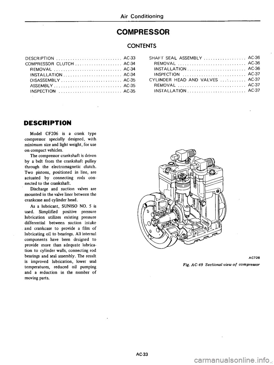
DESCR
IPTIDN
COMPRESSOR
CLUTCH
REMOVAL
INSTAllATION
DISASSEMBLY
ASSEMBLY
INSPECTION
DESCRIPTION
Model
CF206
is
a
crank
type
compressor
specially
designed
with
minimum
size
and
light
weight
for
use
on
compact
vehicles
The
compressor
crankshaft
is
driven
by
a
belt
from
the
crankshaft
pulley
through
the
electromagnetic
clutch
Two
pistons
positioned
in
line
are
actuated
by
connecting
rods
coo
nected
to
the
crankshaft
Discharge
and
suction
valves
are
mounted
in
the
valve
liner
between
the
crankcase
and
cylinder
head
As
a
lubricant
SUNlSO
NO
5
is
used
Simplified
positive
pressure
lubrication
utilizes
existing
pressure
differential
between
suction
intake
and
crankcase
to
provide
a
film
of
lubricating
oil
to
bearings
All
internal
components
have
been
designed
to
provide
more
than
adequate
lubrica
tion
to
cylinder
walls
connecting
rod
bearings
and
seal
assembly
The
result
is
improved
lubrication
lower
seal
temperatures
reduced
oil
pumping
and
a
reduction
in
the
number
of
moving
parts
Air
Conditioning
COMPRESSOR
AC33
AC34
AC34
AC34
AC35
AC
35
AC35
CONTENTS
SHAFT
SEAL
ASSEMBLY
REMOVAL
INSTAllATION
INSPECTION
CYLINDER
HEAD
AND
VALVES
REMOVAL
INSTAllATION
AC36
AC36
AC36
AC37
AC37
AC37
AC37
AC728
Fig
AC
49
Sectional
view
of
compressor
AC33