engine DATSUN PICK-UP 1977 Service Manual
[x] Cancel search | Manufacturer: DATSUN, Model Year: 1977, Model line: PICK-UP, Model: DATSUN PICK-UP 1977Pages: 537, PDF Size: 35.48 MB
Page 466 of 537
Body
Electrical
System
ELECTRICAL
ACCESSORIES
CONTENTS
HORN
DESCRIPTION
REMOVAL
AND
INSTALLATION
IGNITION
SWITCH
REMOVAL
AND
INSTALLATION
INSPECTION
WINDSHIELD
WIPER
AND
WASHER
REMOVAL
AND
INSTALLATION
INSPECTION
RADIO
REMOVAL
AND
INSTALLATION
ADJUSTMENT
CLOCK
REMOVAL
I
NST
ALLA
TION
HEATER
DESCRIPTION
AIRFLOW
HEATER
UNIT
ASSEMBLY
BE
21
BE
21
BE
21
8E
n
BE
22
BE
22
BE
23
BE
23
BE
23
BE
25
BE
25
BE
25
BE
25
BE
25
BE
26
BE
26
BE
26
BE
28
BE
29
HORN
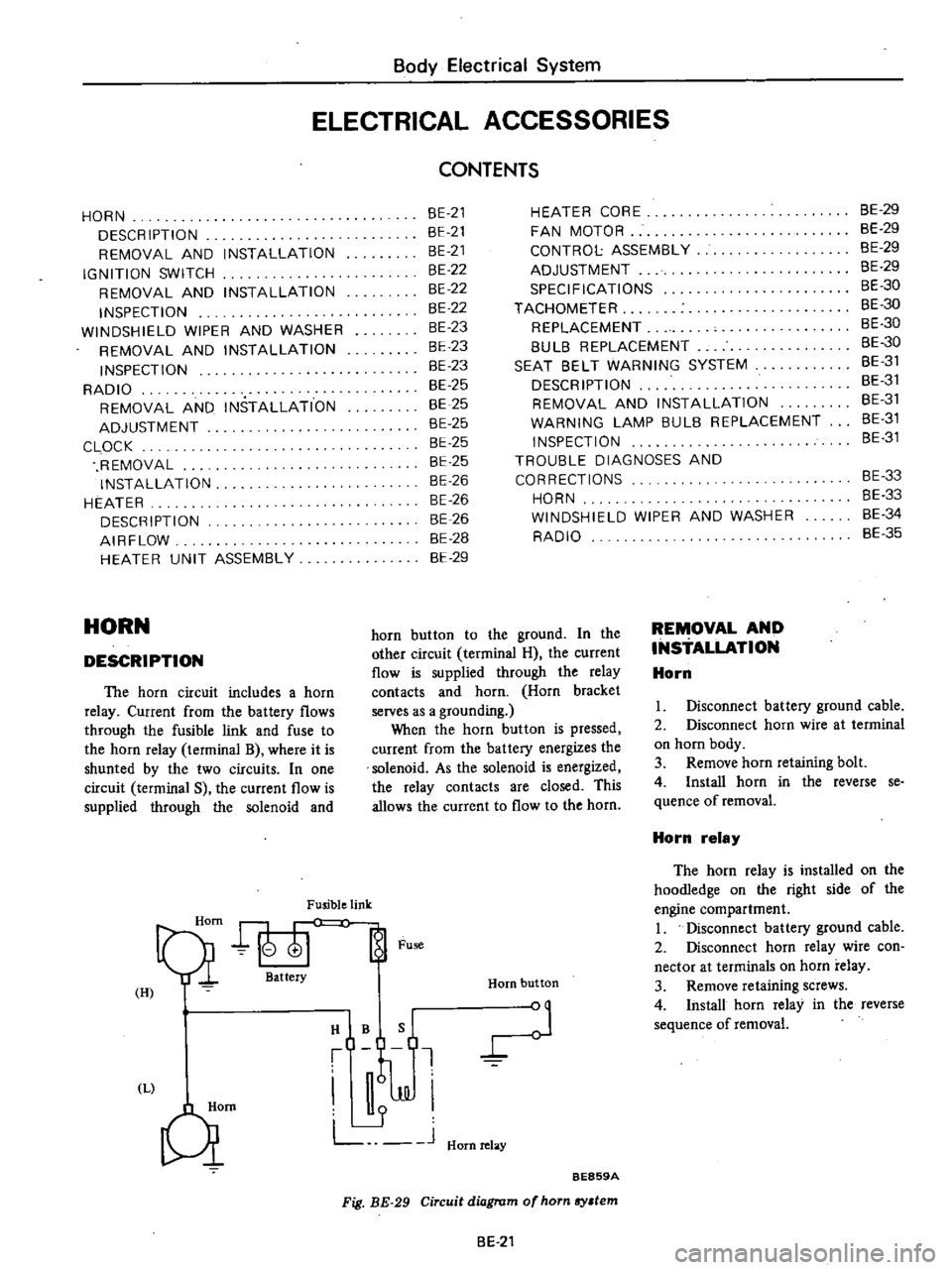
DESCRIPTION
The
horn
circuit
includes
a
horn
relay
Current
from
the
battery
flows
through
the
fusible
link
and
fuse
to
the
horn
relay
terminal
B
where
it
is
shunted
by
the
two
circuits
In
one
circuit
terminal
S
the
current
flow
is
supplied
through
the
solenoid
and
Fusible
link
Qi
att
Fu
H
I
HIBQ
t
J
JJI
L
J
Hornrelay
Qm
HEATER
CORE
FAN
MOTOR
CONTROL
ASSEMBLY
ADJUSTMENT
SPECIFICATIONS
TACHOMETER
REPLACEMENT
8UL8
REPLACEMENT
SEAT
8ELT
WARNING
SYSTEM
DESCRIPTION
REMOVAL
AND
INSTALLATION
WARNING
LAMP
BULB
REPLACEMENT
INSPECTION
TROUBLE
DIAGNOSES
AND
CORRECTIONS
HORN
WINDSHIELD
WIPER
AND
WASHER
RADIO
Horn
button
BE859A
Fig
BE
29
Circuit
diagram
of
horn
sy
tem
horn
button
to
the
ground
In
the
other
circuit
terminal
H
the
current
flow
is
supplied
through
the
relay
contacts
and
horn
Horn
bracket
serves
as
a
grounding
When
the
horn
button
is
pressed
current
from
the
battery
energizes
the
solenoid
As
the
solenoid
is
energized
the
relay
contacts
are
closed
This
allows
the
current
to
flow
to
the
horn
BE
21
REMOVAL
AND
INSTALLATION
Horn
8E
29
BE
29
BE
29
8E
29
BE
30
BE
30
BE
30
8E
30
8E
31
BE
31
BE
31
8E
31
8E
31
BE
33
8E
33
8E
34
BE
35
I
Disconnect
battery
ground
cable
2
Disconnect
horn
wire
at
terminal
on
horn
body
3
Remove
horn
retaining
bolt
4
Install
horn
in
the
reverse
se
quence
of
removal
Horn
relay
The
horn
relay
is
installed
on
the
hoodIedge
on
the
right
side
of
the
engine
compartment
I
Disconnect
battery
ground
cable
2
Disconnect
horn
relay
wire
con
nector
at
terminals
on
horn
relay
3
Remove
retaining
screws
4
Install
horn
relay
in
the
reverse
sequence
of
removal
Page 472 of 537
Operation
of
the
heater
is
control
led
by
two
control
levers
located
on
the
instrument
panel
and
a
hand
op
erated
knob
on
the
center
of
the
heater
unit
The
AIR
LEVER
controls
the
air
intake
valve
and
or
room
valve
by
its
lever
positions
OFF
DEFROST
and
ROOM
through
the
control
cables
The
air
intake
valve
draws
the
fresh
outside
air
from
the
cowl
top
grille
and
supplies
the
air
into
the
heater
unit
The
room
valve
is
located
at
the
bottom
of
the
heater
unit
The
air
coming
through
the
air
intake
valve
opening
is
forced
through
the
heater
core
to
the
room
valve
where
the
air
is
distributed
to
the
floor
outlet
and
or
defroster
outlets
depending
on
the
position
of
the
room
valve
The
VENT
KNOB
is
directly
linked
to
the
vent
valve
which
provides
fresh
air
for
the
passenger
Push
the
knob
all
the
way
in
to
open
the
valve
The
fresh
ventilating
air
comes
out
of
the
heater
center
outlet
The
TEMP
lever
is
a
dual
pur
pose
control
one
is
for
regulating
the
flow
of
engine
coolant
flowing
into
Body
Electrical
System
the
heater
unit
and
the
other
for
the
operation
of
the
fan
motor
When
the
lever
is
in
the
OFF
position
the
water
cock
is
closed
and
the
circulation
of
engine
coolant
through
the
heater
core
stops
When
the
lever
is
slided
to
any
other
position
than
OFF
the
water
cock
opens
in
proportion
to
the
lever
setting
and
allow
engine
coolant
to
flow
into
heater
core
To
control
the
fan
motor
opera
tion
push
or
pull
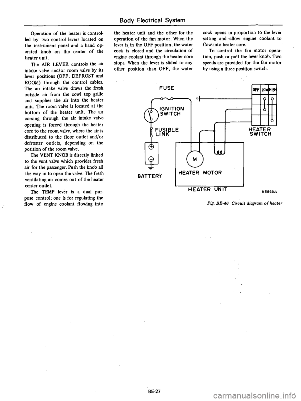
the
lever
knob
Two
speeds
are
provided
for
the
fan
motor
by
using
a
three
position
switch
FUSE
IOfF
UlwlHI
ON
1
t
f
SWITCH
u
FUSI
BlE
rl
HEATE
R
LINK
SWITCH
is
G
luJ
BATTERY
HEATER
MOTOR
H
EATER
UN
IT
BE868A
Fig
BE
46
Circuit
diagram
of
heater
8E
27
Page 474 of 537
HEATER
UNIT
ASSEMBLY
Removal
L
Disconnect
battery
ground
cable
2
Drain
engine
coolant
3
Remove
defroster
hoses
4
Remove
three
cable
retaining
clips
and
disconnect
control
cables
from
valves
and
water
cock
5
Disconnect
two
fan
motor
lead
wires
from
each
connector
6
Disconnect
two
resistor
lead
wires
from
each
connector
7
Disconnect
water
hoses
from
core
and
water
cock
8
Remove
three
heater
housing
mounting
bolts
and
dismount
heater
unit
from
vehicle
Installation
1
Position
heater
unit
under
instru
ment
panel
and
install
three
heater
unit
securing
bolts
2
Install
water
hoses
3
Position
heater
control
cables
to
room
valve
air
intake
valve
and
water
cock
4
Adjust
control
cable
length
for
proper
operation
as
outlined
in
Adjust
ment
5
Connect
fan
motor
wires
and
resistance
wires
to
each
connector
plug
6
Install
defroster
hoses
7
Connect
battery
ground
cable
8
Fill
cooling
systeIT
9
Run
engine
at
2
000
rpm
with
AIR
lever
in
the
HOT
position
Make
sure
that
engine
coolant
is
fIlled
up
to
correct
level
HEATER
CORE
Removal
and
installation
L
Drain
engine
coolant
2
Remove
defroster
hoses
3
Disconnect
water
hoses
from
inlet
and
outlet
pipes
of
heater
core
4
Remove
four
clips
and
front
cover
Body
Electrical
System
BE869A
Fig
BE
48
Removing
front
cov
r
S
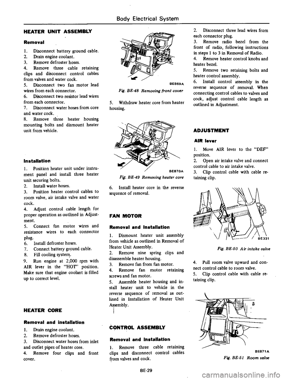
Withdraw
heater
core
from
heater
housing
BE870A
Fig
BE
49
Removing
heater
core
6
Install
heater
core
in
the
reverse
sequence
of
removal
FAN
MOTOR
Removal
and
Installation
L
Dismount
heater
unit
assembly
from
vehicle
as
outlined
in
Removal
of
Heater
Unit
Assembly
2
Remove
nine
spring
clips
and
disassemble
heater
housing
3
Remove
fan
from
fan
motor
4
Remove
fan
motor
retaining
screws
and
fan
motor
S
Assemble
heater
housing
and
in
stall
heater
unit
to
vehicle
in
the
reverse
sequence
of
removal
as
out
lined
in
Installation
of
Heater
Unit
Assembly
I
CONTROL
ASSEMBLY
Removal
and
Installation
I
Remove
three
cable
retaining
clips
and
disconnect
control
cables
from
valves
and
cock
BE
29
2
Disconnect
three
lead
wires
from
each
connector
plug
3
Remove
radio
bezel
from
the
front
of
radio
following
instructions
in
steps
I
to
3
in
Removal
of
Radio
4
Remove
heater
control
knobs
and
heater
bezel
5
Remove
two
retaining
bolts
and
heater
control
assembly
6
Install
control
assembly
in
the
reverse
sequence
of
removal
When
connecting
control
cables
to
valves
and
cock
adjust
control
cable
length
as
outlined
in
Adjustment
ADJUSTMENT
AIR
lever
L
Move
AIR
lever
to
the
DEF
position
2
Open
air
intake
valve
and
connect
control
cable
to
air
intake
valve
3
Clip
control
cable
with
cable
re
taining
clip
Fig
BE
50
A
iT
intake
valve
4
Pull
room
valve
upward
and
con
nect
control
cable
to
room
valve
5
Clip
control
cable
with
cable
re
taining
clip
BE871A
Fig
BE
51
Room
valve
Page 475 of 537
TEMP
lever
1
Move
TEMP
lever
to
the
OFF
position
2
Connect
control
cable
to
the
lever
of
water
ock
when
water
cock
lever
is
pulled
forward
fully
closed
3
Install
control
cable
on
water
cock
bracket
with
cable
retaining
clip
SPECIFICATIONS
Item
FAN
MOTOR
Rated
power
consumption
Revolution
rpm
Fan
dia
mm
in
TACHOMETER
The
tachometer
is
optional
on
model
HL620
It
is
an
integral
part
of
the
ignition
system
It
counts
the
pulses
entering
the
ignition
coil
and
indicates
the
number
of
engine
revolu
tions
REPLACEMENT
I
Remove
battery
ground
cable
2
Remve
cluster
lid
following
instructions
iri
steps
I
to
4
of
Removal
in
Combination
Meter
Body
Electrical
System
BE872A
Fig
BE
52
Water
cock
General
use
Extremely
cold
weather
use
2
RG
The
red
with
green
stripe
lead
wire
must
be
connected
to
flat
plate
terminal
at
back
of
combination
meter
3
B
The
black
lead
wire
must
be
connected
to
T
shaped
ter
minal
at
back
of
combination
meter
4
YR
The
yellow
with
red
stripe
lead
wire
must
be
connected
to
pole
terminal
at
back
of
combination
meter
6
Pass
tachllmeter
wires
through
grommet
on
hood
lock
control
wire
and
connect
to
negative
terminal
of
ignition
coil
Notes
a
Fix
grommet
with
an
adhesive
tape
or
a
sealing
compound
to
prevent
water
leakage
b
Attach
tachometer
wires
to
hood
lock
control
wire
with
an
adhesive
tape
BULB
REPLACEMENT
I
Remove
tachometer
as
previously
described
2
Twist
illumination
bulh
socket
at
back
of
tachometer
Bulb
with
socket
can
then
be
easily
removed
3
Remove
bulb
4
Install
new
bulb
in
reverse
se
quence
of
removal
Bulb
wattage
Tachometer
illumination
lamp
3
4W
12V
less
than
36W
3
600
110
433
12V
less
than
SSW
2
SOO
110
4
33
3
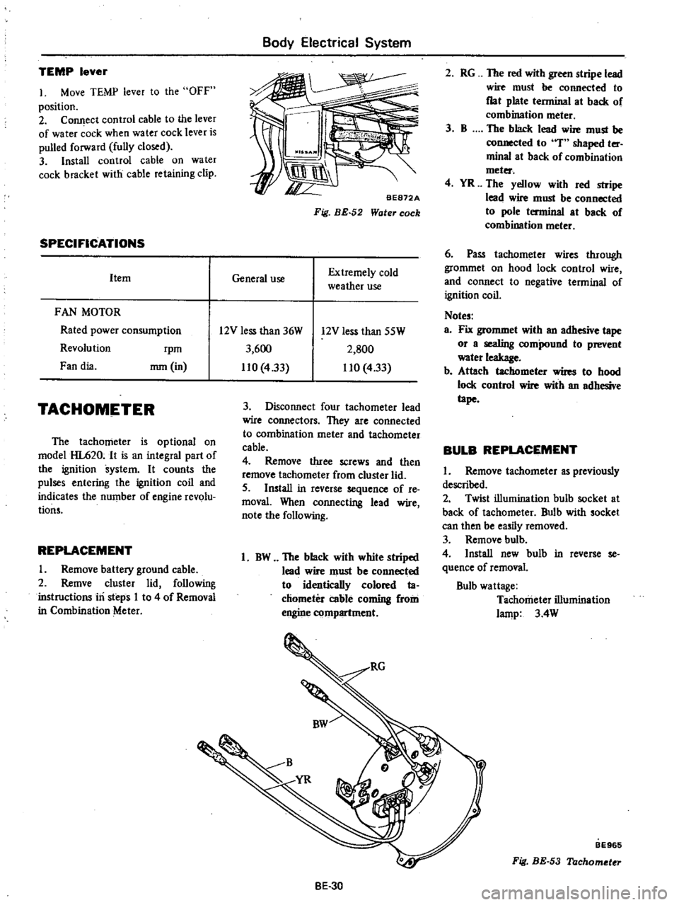
Disconnect
four
tachometer
lead
wire
connectors
They
are
connected
to
combination
meter
and
tachometer
cable
4
Remove
three
screws
and
then
remove
tachometer
from
cluster
lid
5
Install
in
reverse
sequence
of
re
moval
When
connecting
lead
wire
note
the
following
1
BW
The
black
with
white
striped
lead
wire
must
be
connected
to
identically
colored
ta
chometer
cable
coming
from
engine
compartment
BE
30
BE965
Fig
BE
53
Tachometer
Page 480 of 537
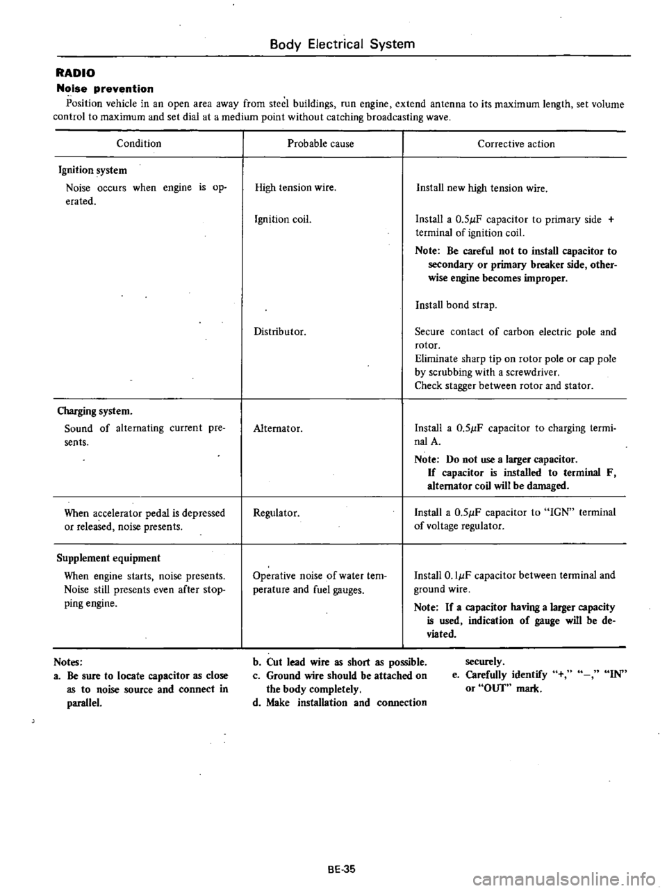
Body
Electrical
System
RADIO
Noise
prevention
Position
vehicle
in
an
open
area
away
from
steel
buildings
run
engine
extend
antenna
to
its
maximum
length
set
volume
control
to
maximum
and
set
dial
at
a
medium
point
without
catching
broadcasting
wave
Condition
Ignition
system
Noise
occurs
when
engine
is
op
erated
Charging
system
Sound
of
alternating
current
pre
sents
When
accelerator
pedal
is
depressed
or
released
noise
presents
Supplement
equipment
When
engine
starts
noise
presents
Noise
still
presents
even
after
stop
ping
engine
Notes
a
Be
sure
to
locate
capacitor
as
close
as
to
noise
source
and
connect
in
parallel
Probable
cause
Corrective
action
High
tension
wire
Install
new
high
tension
wire
Ignition
coil
Install
a
0
51lF
capacitor
to
primary
side
terminal
of
ignition
coil
Note
Be
careful
not
to
install
capacitor
to
secondary
or
primary
breaker
side
other
wise
engine
becomes
improper
Install
bond
strap
Distributor
Secure
contact
of
carbon
electric
pole
and
rotor
Eliminate
sharp
tip
on
rotor
pole
or
cap
pole
by
scrubbing
with
a
screwdriver
Check
stagger
between
rotor
and
stator
Alternator
Install
a
0
51lF
capacitor
to
charging
termi
nalA
Note
Do
not
use
a
larger
capacitor
If
capacitor
is
installed
to
terminal
F
alternator
coil
will
be
damaged
Regulator
Install
a
0
51lF
capacitor
to
IGN
terminal
of
voltage
regulator
Operative
noise
of
water
tem
perature
and
fuel
gauges
Install
O
IIlF
capacitor
between
terminal
and
ground
wire
Note
If
a
capacitor
having
a
larger
capacity
is
used
indication
of
gauge
will
be
de
viated
b
Cut
lead
wire
as
short
as
possible
c
Ground
wire
should
be
attached
on
the
body
completely
d
Make
installation
and
connection
securely
e
Carefully
identify
or
OUT
mark
IN
BE
35
Page 481 of 537

CD
m
Cl
@
D
@
I
j
1
To
instrument
harness
IS
To
battery
30
To
check
connector
2
To
full
transistor
amplifier
16
To
fusible
link
3t
To
headlamp
L
U
type
2
California
models
only
17
To
engine
harness
No
2
32
To
sido
marker
lamp
L
B
3
To
hood
switch
18
To
alternator
33
To
front
combination
lamp
L
H
4
To
engine
compartment
lamp
1
9
To
front
combination
lamp
R
n
34
To
horn
Low
ll
l
S
To
washer
motor
20
To
headlamp
R
H
type
2
3S
To
horn
High
l
l
0
6
To
auto
choke
heater
relay
1
To
side
marker
lamp
R
n
36
To
B
C
D
D
cut
olenoid
California
models
7
To
detector
dri
e
counter
22
To
headlamp
R
B
type
1
only
Non
Califunia
model
except
for
Canada
23
To
ground
37
To
block
tcrminal
distributor
California
8
To
ignition
relay
California
models
only
i4
To
thermal
transmitter
models
only
9
To
floor
sensor
relay
California
modeb
only
is
To
distributor
Non
California
models
only
38
To
ignition
coil
Non
California
models
only
n
10
To
inhibitor
relay
A
T
only
26
To
8
C
D
D
cut
solenoid
Non
California
39
To
condenser
t
II
To
head
lamp
relay
models
only
40
To
ignition
coil
and
resistor
@
12
To
horn
relay
27
To
fuel
cut
solenoid
California
models
only
OJ
v
m
13
To
voltage
regulator
28
To
auto
choke
heater
g
e
14
To
cooler
cable
29
To
headlamp
L
R
type
1
OJ
to
o
Q
m
r0
C
1
i
Ql
CIl
Il
l
3
Page 483 of 537

m
ii
bl
l
l
l
if
3
i
m
1
Kickdown
solenoid
AlT
2
Oip
3
Inhibitor
switch
AfT
4
Oip
5
Engine
6
Battery
cable
7
Engine
slinger
8
Battery
cable
r
0
w
I
I
cf
n
L
J
TO
ENGtNE
ROOM
HARNESS
OJ
o
Q
m
O
Q
CIl
II
D
3
Page 484 of 537

m
W
D
to
l
l
0
c
l
l
s
Q
3
For
Automatic
Transmission
LB
B
For
Manual
Transmission
m
For
Automatic
Transmission
COLOR
CODE
B
Black
BI
Brown
G
Green
L
Blue
Lg
Light
green
R
Red
W
White
Y
Yellow
BW
Black
with
white
stripe
LgR
Light
green
with
red
stripe
BY
RB
RB
B
WB
RB
YB
2
RB
I
B
1
BW
r
BY
LB
For
Automatic
Transmission
to
o
c
m
r0
O
O
Dl
For
Manual
Transmission
@
CJ
lti
3
RB
fB
BY
YB
RB@RB
YB
BY
1
To
kickdown
solenoid
fOT
Automatic
Transmission
2
To
reverse
switch
for
Manual
Tranmission
3
To
inhibitor
switch
for
Automatic
Transmission
4
To
oil
pressure
switch
5
To
starter
motor
6
To
engine
room
harness
for
Manual
Transmission
7
To
engine
room
harness
for
Automatic
Transmission
Page 485 of 537

m
J
c
@
@
r
1
I
I
I
II
U
j
J
r
U
I
IT
L
U
L
L
@
Qj
flll
I
1
I
I
1
lL
to
t
l
Q
1
To
room
Jamp
cable
2
To
light
switch
3
To
fuse
4
To
tachometer
or
clock
5
To
hazard
flasher
unit
6
To
stop
lamp
switch
7
To
ignition
switch
8
To
hazard
switch
9
To
tU
and
dimmer
switch
10
To
check
connector
11
To
AMP
M
T
only
11
To
combination
instrument
Non
California
mode15
except
for
Canada
13
To
combination
meter
14
To
flasher
unit
IS
To
kickdown
switch
AfT
only
16
To
hand
brake
switch
17
To
heater
motor
18
To
illumination
control
rheostat
19
To
wiper
switch
light
switch
illumination
lamp
20
To
wiper
switch
21
To
cigar
lighter
22
To
heater
control
illumination
lamp
23
To
radio
24
To
heater
control
25
To
belt
and
E
G
R
warning
lamp
Non
California
models
or
floor
te
peratuJe
California
models
26
To
heater
control
illumination
lamp
27
To
buzzer
28
To
belt
warning
timer
U
S
A
Olodels
29
To
indicator
lamp
AfT
only
30
To
cooler
harness
31
To
wiptr
motor
32
To
door
switch
R
H
33
To
engine
compartment
harness
34
To
floor
harness
E
m
S
@
o
J
o
Q
m
CD
n
Ql
en
I
i
3
Page 486 of 537

@
BG
B
LW
LW
B
L
AL
l
J
YA
CD
m
LW
4
ft
GL
LR
t4
B
t
R
LG
4D
It
GW
BW
GW
L
@
ii
b
l
l
l
lD
m
en
lD
A
A
G
Ri
G
L
Non
California
except
Canada
I
G
GR
13
L
R
j
M
T
only
GL
A
T
only
To
engine
compartment
harness
Non
california
except
Canada
G
r
wRfl
Lt
IIY
LIB
l
ll
RY
R
oIll
CD
o
c
m
o
O
II
fJl
1
3